Mitsubishi Electric PAR-SE9FA-E User manual

Type
User manual

Mitsubishi Electric PAR-SE9FA-E is a wireless signal receiver designed to seamlessly integrate with your compatible Mitsubishi Electric air conditioning system, offering enhanced remote control capabilities. It allows you to remotely control and monitor your air conditioner using a wireless remote controller, providing the utmost convenience and ease of use.

Mitsubishi Electric PAR-SE9FA-E is a wireless signal receiver designed to seamlessly integrate with your compatible Mitsubishi Electric air conditioning system, offering enhanced remote control capabilities. It allows you to remotely control and monitor your air conditioner using a wireless remote controller, providing the utmost convenience and ease of use.

E-186
OPTIONAL
PARTS
Figure
Specications
PAR-SE9FA-E
Unit : mm
Descriptions
Applicable Models
Dimensions
Signal Receiver
Integrate the Signal Receiver in the corner panel.
Applicable only for PLA-ZM EA, PLA-M EA,
PLA-SM EA models.
PLA-ZM·EA series
PLA-M·EA series
PLA-SM·EA series
Model name PAR-SE9FA-E
Operation
indicator lamp
During operation: LED (green) lights, Abnor-
mal condition: LED (green) blinks, Preparing
for heating operation:LED.(orange) lights
Emergency operation Cooling/heating switch (operate/stop)
equipped.
Number of
controllable units
Maximum 16 refrigerant systems in one group
(At least one wireless signal receiving kit must
be installed to each refrigerant system.)
Adapter wiring Connect the 9-core cord with connector
(attached) to CN90 of the indoor controller
board.
Signal distance Within 7m in 45 degrees range from the
front of the Signal Receiver
185
18529
Grille
Signal Receiver
E-187
OPTIONAL
PARTS
How to Use / How to Install
Signal Receiver PAR-SE9FA-E
1
2
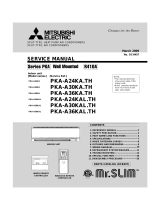
Preparation for installing SIGNAL RECEIVER
Installing SIGNAL RECEIVER
Pair number of indoor unit
No need to cut.
Cut only J41.
Cut only J42.
Cut J41 and J42.
SW 22-3
ON
OFF
ON
OFF
SW 22-4
ON
ON
OFF
OFF
0
1
2
3
1. Open the intake grille and remove the corner panel. The corner
panel is in opposite to where refrigerant pipes are (where local
wires are drawn into).
Note:
Discard only the removed corner panel.
Reuse the screw of the removed corner panel to install the signal
receiver.
When installing the signal receiver during grille installation,
complete the wiring work of grille before proceeding to the
following procedure.
2. Loosen the 2 screws on the electrical box cover, and remove the
cover by sliding; however, in this installation, the cover can hang
temporarily.
3. Specify the target unit for wireless remote controller operation.
Follow the procedure below to set the pair number on the indoor
controller board and the wireless remote controller.
■ Setting pair number
The pair number setting is to specify the unit which is to be
operated by wireless remote controller.
When specifying the unit is not required, this setting is not
necessary.
The pair number is set to “0” on indoor unit (signal receiver)
side and wireless remote controller side at an initial setting.
When specifying the unit is required, match the pair number on
the indoor unit (signal receiver) side and on the wireless remote
controller side as shown in the table below.
When the unit is in combination with PLFY-EM
Set SW22.
When the unit is in combination with PLA-EA
Cut jumper wire J41, J42, or both on the
indoor controller board.
Pair number of wireless
remote controller
Make sure to turn off the main power before work.
Refrigerant pipe
Electrical box cover Main unit
Drain pipe
Indoor controller board
Grille
Intake grille
Corner panel
Screw
Screw
Signal receiver
Square hole Hooking portionslead wire
Cable band
Installation procedure for the default location
1. Pull out the lead wire of signal receiver from the square hole located in the corner of grille, where the removed corner panel was in
the preparation procedure.
2. Pass the lead wire through the 2 hooking portions and inside the electrical box, and connect it to CN90 on the indoor controller
board as shown below.
Adjust the lead wire length to allow the corner panel to be removed again, and fix it with the cable band.
3. Install the signal receiver by sliding it towards the arrow A, and fix in the corner with the screw.
(Reuse the screw which was used to fix the removed corner panel.)
4. After completing the installation, attach the electrical box cover and the intake grille as they were.
CN90 on indoor
controller board
E-188
OPTIONAL
PARTS
Signal Receiver PAR-SE9FA-E
● To install the signal receiver to the 2 locations other than the default location, follow the procedure below.
Prohibited location to
install the signal receiver
Drain pipe Refrigerant pipe
Screws for
the electrical
box cover
Screw
CN90 on indoor
controller board
Electrical box
Clamp
Screws for
the electrical
box cover
CN90 on indoor
controller board
Electrical box
Screw
Cable band
Default location of signal
receiver installation
Alternative location 2 to install
the signal receiver
(Air outlet identification marks )
Alternative location 1 to install
the signal receiver
(Air outlet identification marks )
Installation procedure for the alternative location
1
1. Pass the lead wire of signal receiver through the square hall
located in the corner of grille.
2. Loosen the 2 screws fixing the electrical box cover on the
unit, and slide the cover to open.
3. Route the lead wire of signal receiver (white, 9 poles) from
the electrical box side on the unit, and certainly connect it to
CN90 on the indoor controller board.
4. The lead wire of signal receiver must be held together
without slack using the clamp into the electrical box.
5. Follow the reverse procedure of 2 to reinstall the electrical
box cover on the unit.
6. Install the signal receiver to the grille and fix with the
screws.
Installation procedure for the alternative location
2
1. Pass the lead wire of signal receiver through the square hall
located in the corner of grille.
2. Loosen the 2 screws fixing the electrical box cover on the
unit, and slide the cover to open.
3. Route the lead wire of signal receiver (white, 9 poles) from
the electrical box side on the unit, and certainly connect it to
CN90 on the indoor controller board.
4. The lead wire of signal receiver must be held together
without slack, and fixed with the cable band into the
electrical box.
5. Follow the reverse procedure of 2 to reinstall the electrical
box cover on the unit.
6. Install the signal receiver to the grille and fix with the
screws.
  • Page 1 1
  • Page 2 2
  • Page 3 3

Mitsubishi Electric PAR-SE9FA-E User manual

Type
User manual

Mitsubishi Electric PAR-SE9FA-E is a wireless signal receiver designed to seamlessly integrate with your compatible Mitsubishi Electric air conditioning system, offering enhanced remote control capabilities. It allows you to remotely control and monitor your air conditioner using a wireless remote controller, providing the utmost convenience and ease of use.

Ask a question and I''ll find the answer in the document

Finding information in a document is now easier with AI