Page is loading ...

Broadcast Warehouse
TX 150/300 FM BROADCAST TRANSMITTER
No part of this manual may be re-produced in any form without prior written permission from Broadcast Warehouse.
The information and specifications contained in this document is subject to change at any time without notice.
Copyright 2001 Broadcast Warehouse
For the latest contact information for Broadcast Warehouse please visit our website at,
www.broadcastwarehouse.com
Technical manual

TX FM Transmitter technical manual page 2
CONTENTS
1. Introduction
1.1 TX FM Transmitter
1.2 Safety
1.3 Front And Rear Panels
1.4 Control And Monitor LCD
2. Installation And Setup
2.1 Frequency Setup
2.2 R.F. Power Setup
2.3 Alarms
2.4 RS232 Control & Monitoring
2.41 RS232 Interface board
2.42 Windows application
2.43 Terminal control
2.5 Modes Of Operation
2.51 A guide to the jumpers
2.52 Multiplex / Broadband Input
2.53 Stereo With Limiters
2.54 Stereo With Limiters Disabled
2.55 Mono From Two Channels
2.56 Mono From One Channel
2.6 Other Setup Considerations
3. Technical data
3.1 Specifications
3.2 Circuit Description
3.3 Block Diagram
3.4 Internal Wiring / Case Overview
3.5 Schematics
3.51 LCD Control Section
3.52 Power Amplifier Section
3.53 All In One Exciter Section
3.531 Limiter Section
3.532 Coder Section
3.533 Exciter Section
3.6 Parts List
3.61 LCD Control board parts list
3.62 Power Amplifier board parts list
3.63 Combo board parts list

TX FM Transmitter technical manual page 3
Introduction
1.1 TX 150/300 FM TRANSMITTER
The Broadcast Warehouse TX 150/300 is a high specification FM broadcast transmitter. Its broadband “no-tune”
design allows 87.5-108 Mhz operation from internal direct reading rotary switches or the front panel LCD frequen-
cy control system if enabled. Digital PWM techniques provide an easily adjustable and accurate automatic level
controlled R.F. output of the Mos-Fet power amplifier stage.
R.F., Audio and other parameters are shown on the LCD graphics display. This display offers a very easy method
of transmitter parameter monitoring and a new level of ease for setup and installation, with metering accuracy nor-
mally only found on expensive test equipment. Local and remote personal computer control and metering are
achievable via the innovative dual method RS232 interface.
The FM modulator section employs a dual speed “virtual VFO” system for extremely low audio distortion and
excellent stereo performance.
A built in high specification stereo encoder provides crystal clear stereo sound and combined with the internal lim-
iter a fully compliant “plug and play” all in one low power broadcast transmitter.
For future compatibility all settings are switchable with on board jumpers. The stereo and/or limiter settings can be
switched in and out to suit the requirements of any external broadcast equipment you may have now and in the
future.
The lightweight universal mains input design ensures a high reliability efficient design compatabile with any mains
system in the world.

TX FM Transmitter technical manual page 4
Introduction
1.2 SAFETY
MAINS VOLTAGE.
This equipment operates from an AC power source of between 90 and 265 volts. There are hazardous
voltages present internally. PLEASE OBSERVE CAUTION WITH THE COVER REMOVED.
SWITCHED MODE POWER SUPPLY HAZARD
Please note that the power supply units in this equipment is of the switched mode variety and have lethal
voltages present internally. The switched mode supplies are universal input fully approved type. They are
non serviceable modules and should be fully replaced should they fail.
FUSES
Only use fuses with the specified voltage and current ratings as stated on the back panel. Failure to do so
may increase the risk of equipment failure, shock and fire hazard.
R.F.
The N type R.F. power output socket contains R.F. voltages which may burn or present a shock. Please
make sure that the equipment is connected to an adequately rated load or antenna system while in opera-
tion.
TOXIC HAZARD
This equipment includes R.F. components that may contain Beryllium oxide which is a highly toxic sub-
stance that could be hazardous to health if inhaled or ingested. Care should be taken when replacing or
discarding such devices. Seek expert advice from the manufacturer should you physically damage a device
that contains Berillyium Oxide.
The main R.F. output power transistor contains Beryllium oxide.
OTHER SAFETY CONSIDERATIONS
Do not operate this equipment in the presence of flammable gases, fumes or liquids
Do not expose this equipment to rain or water.

TX FM Transmitter technical manual page 5
Introduction
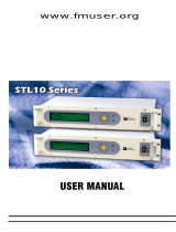
1.3 FRONT AND REAR PANELS
FUSE
1234567 8 911 13
12
10
TX150/300 FM TRANSMITTER
1. Left audio input
2. Left Input gain
3. Right input gain
4. Right audio input
5. MPX output
6. MPX level control
7. MPX Input
8. Control / Logic
9. R.F. output
10 LCD display
11. Power socket
12. Up / Down frequency buttons
13. Chassis ground post.
Control / logic D-type pin out
Pin 1 PLL failure alarm (O/C)
Pin 2 Reserved
Pin 3 Reserved
Pin 4 R.F. failure alarm (O/C)
Pin 5 R.F. failure alarm (TTL)
Pin 6 Mod failure alarm (TTL)
Pin 7 PLL failure alarm (TTL)
Pin 8 R.F. Mute (Connect to GND for mute)
Pin 9 Mod failure alarm (O/C)
Pin 10 RS232 TXD
Pin 11 RS232 RXD
Pin 12 Reserved
Pin 13 Reserved
Pin 14 +18 VDC 200mA
Pin 15 GND
XLR Audio input connectors
Pin 1 Ground
Pin 2 Hot
Pin 3 Cold
3
21
15 14 13 12 11 10 9
8 7 6 5 4 3 2 1
Front panel:
R.F. MONITOR: -50dBC ( Not suitable for harmonic measurements )
MOD. MONITOR: ( Buffered multiplex, Nominally 3 V peak to peak for 75 KHz )

TX FM Transmitter technical manual page 6
Introduction
1.4 CONTROL AND MONITOR LCD
The front panel LCD graphics display has seven screens (shown below). These allow monitoring of the transmit-
ter’s R.F., audio and other parameters and the adjustment (if internally allowed) of the transmitter’s power and fre-
quency. You can move through the screens by pressing the NEXT button, which will display them in the following
order.
Main parameter screen.
This shows together the three most important transmitter
parameters. Frequency, R.F. output power and the peak
deviation.
Frequency display and control
This screen will display the frequency and PLL locked condi-
tion. The up and down buttons will allow 100 KHz frequency
steps from 87.5 to 108Mhz if the internal switches are set to
4440. If the frequency is set internally with the rotary switch-
es then the up / down buttons will give a ‘not allowed’ mes-
sage
R.F. power
The forward and reverse R.F. powers are displayed. The
up/down buttons will allow power control if internally allowed.
The maximum output power is governed by the maximum
power set adjustment (see R.F. pwr control section). If the
frequency is set internally with the rotary switches then the
up / down buttons will give a ‘not allowed’ message
Peak deviation
This display indicates the peak and average deviation. Peak
deviation is shown both numerically and as a moving single
pixel wide bar. Average deviation is shown with the solid
black bar. Over-deviation will display an exclamation ( ! )
Gain reduction
This display indicates the amount of gain reduction of the
internal audio limiter. The range is 0 to 24 decibels of gain
reduction.
Power supply
Power amplifier voltage is shown together with the transmit-
ters secondary supply that feeds the exciter section. The
power amplifier voltage will vary depending on set output
power and the presence of any fault conditions which also
cut the voltage back and with it the R.F. output.
P.A. temperature
This display indicates the temperature of the heatsink that
the R.F. power transistor is bolted to. The normal operating
temperature range is 40-60 degrees at full R.F. power out-
put.

TX FM Transmitter technical manual page 7
Installation and setup
2.1 FREQUENCY SETUP
The Frequency can be set on the transmitter in one of two ways:
1. From internal direct reading decimal switches on the main board
2. From the front panel LCD display and front panel buttons.
Many radio regulatory bodies stipulate that the transmitters parameters including the frequency must not be easily
changed from the front panel. To meet this requirement you will need to set the frequency internally with the dial
switches.
The switches have a silkscreen diagram next to them on the board (see diagram below) clearly indicating what
each switch represents.
The top dial switch represents the value selected x 10 Mhz with the exception of ‘0’ which represents 10 so when
selected would equal 100 Mhz.
The second dial switch represents the value selected x 1 Mhz.
The third dial switch represent the value selected x .1 Mhz (100 KHz)
The bottom switch represents the value selected x .0125 Mhz (12.5 KHz)
For example:
FREQ SWITCHES (MHZ)
X10 X1 X.1 X.0125
87.90 ‘8’ ‘7’ ‘9’ ‘0’
98.75 ‘9’ ‘8’ ‘7’ ‘4’
100.00 ‘0’ ‘0’ ‘0’ ‘0’
104.225 ‘0’ ‘4’ ‘2’ ‘2’
108.00 ‘0’ ‘8’ ‘0’ ‘0’
As you can see, the switches directly read the frequency with the exception of
frequencies above 100 Mhz, where the top switch being set at ‘0’ represents
‘10’. The X0.125 ‘offset’ switch is only used when you want to provide a shift to
the carrier of between 12.5 KHz and 112.5 KHz. Note that setting the switch
on 8 or 9 will have the same effect as setting the previous switch (100 KHz) 1
position higher, as 8 represents 100 KHz on the 12.5 KHz switch. 8 x 0.125MHz = 0.1MHz = 100KHz
The LCD display on the front panel will display the frequency that you have set on the internal switches. If you try
to adjust the frequency with the front panel up / down buttons you will get a ‘ NOT ALLOWED ‘ message appear-
ing on the LCD display. This protects against unauthorized front panel frequency changes when the frequency
has been set internally with the dial switches.
The TX will load the switch values at power up. You will need to remove the mains power to the transmitter
and then reapply it if you want to change the frequency by using the direct reading switches
LCD front panel frequency selection.
If you want to control the frequency from the front panel LCD control
system you will need to set the internal switches to 4440. The trans-
mitter will pass frequency control to the LCD control system and the
frequency can be moved up and down by pressing the NEXT button
until the frequency menu is displayed. The other two buttons control
the UP and DOWN frequency selection. PLL lock status is also dis-
played on this screen.
The LCD readout will only display frequencies in 100Khz steps. Any frequency offsets derived from the
internal 12.5KHz offset switch will not show on the LCD. Consult a frequency counter if using offsets.
Note that some pcb’s have “set to 4444 for
front panel LCD control”. This is an error that
will cause a +50KHz offset to the frequency
set on the LCD screen. Please set to 4440
unless you specifically want the offset.
Frequency selection switches on main board
Fine frequency control. Do not adjust unless you
know what you are doing. Consult advanced setup
section of manual for more information.

TX FM Transmitter technical manual page 8
Installation and setup
2.2 R.F. POWER SETUP
The R.F. power output from the transmitter can be controlled by an analogue potentiometer (POT) or from the
front panel LCD screen or a combination of both.
ANALOGUE POWER CONTROL
If the frequency is set internally with the dial switches you will not be able to adjust the power from the LCD
screen. This is to comply with regulatory body’s that stipulate that the transmitter is not to have it’s parameters
adjustable from the front panel. In this case you must use the maximum power set control to set the transmitters
power. This control will give the full power range adjustment.
If the transmitter has been internally set to 4440 with the dial switches then you can also control the power from
the LCD screen’s R.F. power menu’s up and down buttons. A “not allowed” message will be displayed to the user
if the dial switches are not set to 4440
RS232 power control will over-ride the power control restrictions caused by having the frequency set
internally (not set to 4440).
DIGITAL POWER CONTROL
When the power is to be controlled from the front panel the max power set POT takes on a new role of setting the
maximum power of the transmitter. If you want the LCD screen to have full power range control of the transmitter
you will need to ensure that the max power set control is at maximum power. Otherwise your control range may
be limited. This feature enables you to limit the transmitters maximum power to a fixed level but to still allow the
LCD screen to provide adjustment of the R.F. power down from that maximum power set point. This can be desir-
able in transmitter hire situations where you wish to govern the maximum
output to a fixed level but to allow the customer (hirer of the transmitter) to
run the power of the transmitter at a lower level if they so decide.
The maximum power set is positioned to the lower left of the LCD screen on
some models, other models may not have the hole in the front panel and you
will need to remove the lid of the transmitter to access the adjustment which will be in the same position but on
the other side of the PCB. You will need a small ‘tweaker style’ flathead screwdriver to adjust the pot. This control
is quite delicate so try to not be too heavy handed in it’s adjustment.
Please note that the VSWR and temperature protection circuitry will turn back the R.F. power if a fault con-
dition exists. Make sure that you have a good VSWR (low reverse power reading) before setting the R.F.
power as the removal of a fault condition may cause the R.F. power to increase.
RF POWER MUTE (analogue)
There is a pin (8) on the back panel D-type that can be pulled low to mute the
transmitters RF power. The RS232 interface board also has a connection to mute
the RF this way. Consult the RS232 section of this manual for more information.
RF POWER MUTE (digital/RS232)
The transmitters RF power output can be muted via the RS232 control system.
Terminal software can mute/unmute the RF power with the ‘o’ and ‘f’ commands
respectively.
The windows application has a button that can toggle the RF output of the trans-
mitter.
please consult the RS232 section of this manual for more information on controlling the transmitter remote-
ly.

TX FM Transmitter technical manual page 9
Installation and setup
2.3 ALARMS
The Transmitter has three alarms that can alert the broadcaster if one of the following fails:
R.F. POWER, PLL LOCK, MODULATION
The alarms when set are available on the back panel D-type. Each alarm has an Open collector and a TTL level
contact on the D-type. The alarm induced active open collectors can pull down any external signals and the TTL
outputs will provide a 5 Volt indication. The alarm is also visible if any RS232 monitoring is employed.
For the alarms to function correctly the transmitter must be left on the default menu screen. This is the screen that
displays frequency, R.F. power and peak deviation. To ensure that the alarm system functions correctly the trans-
mitter will return to the default menu screen if the LCD is left on another menu screen for more than 5 minutes.
R.F. POWER.
The R.F. power alarm will be set if the R.F. power falls below a threshold level during normal operation.
This threshold is set below the normal operating lowest wattage available from the transmitter. If you
require a different setting for the alarm, contact our tech dept. The alarm will only be set if the fault condi-
tion exists for sixty seconds or more. You will need to reset the transmitter to clear the alarm/s.( also see
RS232)
PLL LOCK.
The PLL lock alarm will be set if the transmitters falls out of frequency lock during normal operation. The
alarm will only be set if the fault condition exists for sixty seconds or more. You will need to reset the trans-
mitter to clear the alarm/s.( also see RS232)
MODULATION FAILURE.
The Modulation failure alarm will be set if during normal operation the peak deviation of the transmitter
drops and remains below 16 KHz. The 16 KHz alarm level allows the alarm to be set if the audio feed to
the transmitter fails even if the stereo pilot internal to the transmitter is still modulating the transmitter. The
alarm will only be set if the fault condition exists for sixty seconds or more. You will need to reset the trans-
mitter to clear the alarm/s.( also see RS232)
MORE INFO ON ALARMS
The three alarms are available on the back panel D-type connector. The pin-outs are shown on the rear
panel diagram. The three alarms are available as TTL level and as open collector outputs. The TTL level
outputs are active high in the event of an alarm. The open collector outputs are ON in the event of an
alarm and will pull down any external levels. The open collectors can sink 100mA MAX with an absolute
maximum switched voltage of 25 volts.
The D-type connector can also supply 18 volts at 200mA that can be used for pull-ups on the open collector
alarm outputs and for your own external switching circuitry. Broadcast warehouse can also supply custom
plug in PCB’s for the D-type that will allow N+1 control. Two transmitters can be installed in the same rack
and in the event of an alarm being set the external PCB will switch between the main and standby trans-
mitters and if needed switch a coaxial relay.
The RS232 interface provides the ability to reset the alarms. More info is found in the RS232 section of
manual.
Broadcast warehouse can also customise the alarm / fault software to meet the requirements of major
broadcasters and networks. More information on this and other custom features can be obtained from our
technical department.

2.4 RS232 CONTROL AND MONITORING
The TX range of transmitters can be monitored or controlled from a personal computer either locally or remotely.
The Transmitters can “chat” either by a windows application or via a standard serial terminal program. The win-
dows application is the more versatile option and is to be preferred but the ability to use a terminal program can
prove useful in the absence of the windows application or a computer that runs windows.
2.41 RS232 interface board
To connect your TX series transmitter to your serial cable you will need the optional BW TX series RS232 inter-
face board (shown). This board provides
the level conversion required for RS232.
The board also provides an interface to
the various control and alarm signals
present on the transmitters 15 way D-
type connector. For further details of the
alarms please see the back panel con-
nection page of this manual.
The Interface board will push into the
transmitters D-type connector and you
can then break out your other signals via
the push/snap terminals. a 9 way serial
lead from your computer can be plugged
into the expansion boards 9 way D-type
socket..
The above item is an optional extra and
is available from broadcast warehouse and it’s distributors
2.42 Windows application (TXCTRL.EXE)
The latest version of TXCTRL.EXE can be downloaded from...
http://www.broadcastwarehouse.com/downloads
Installation
The windows application is a single file executable that
can be simply run by clicking on it’s ICON. The pro-
gram doesn’t require a setup program and can simply
be copied to the desktop and run as neccessary.
Setup and connection.
Once opened the application will resemble the picture
to the right.
Connect a serial cable between the RS232 board that plugs into the i-o D-type on the rear of the transmitter and
one of your computers COM ports. If you are using a codec or other device then you may be able to connect that
device in line to act as part of the serial link.
The application can connect to either COM port 1 or 2 on the computer that is running the application. Select the
TX FM Transmitter technical manual page 10
Installation and setup
TRANSMITTER
O/C Mod fail
O/C PLL fail
O/C R.F. fail
TTL R.F. fail
TTL Mod fail
TTL PLL fail
R.F. MUTE (PULL LOW FOR MUTE)
GND
COMPUTER
TX SERIES RS232 INTERFACE BOARD
TXCTRL startup screen

COM port you want to use and then click the Connect button.
If the application is able to connect to the trans-
mitter then you will be presented with a screen
similar to the one on the right. Once connected
you should be able to view all the parameters of
the transmitter as well as being able to mute the
R.F., change the frequency, change the R.F.
power and reset any alarm flags that have been
set.
2.43 Terminal control of the transmitter
Installation
Please see the instructions for your terminal software package to find out how
to connect to a remote serial device. The transmitter is internally set to com-
municate at 9600 bps, no parity with 1 stop bit. This is commonly known as
9600 8N1. If your using windows then you can use the pre bundled terminal
program “hyper-terminal”. This is located in the accessories/communications
folder accessible from the start menu. Select direct to com port x where x is
the com port that the transmitter is connected to. You will be presented with a
dialog box like the one shown to the right. Select 9600, 8 , none ,1 with hard-
ware flow control and then click ok.
If you are using another terminal program then you may need to consult the
documentation for that software but it should be pretty much straight forward.
Operation
The transmitter will respond to certain key presses and each one has a certain function. See the list below for
details of what key to press for each function.
The most important key press is the ‘enter’ key. This will need to be
pushed as soon as you connect to the transmitter so you can get the trans-
mitter to refresh your terminal window with the transmitters status and
parameters. (shown on next page)
The transmitter won’t respond to any of the other key presses until it
detects the ‘enter’ key is pressed. Once the enter key is pressed the trans-
mitter will listen out for other key presses for 60 seconds. This Initial ‘enter’
key validation and time window is a safety feature to prevent the transmit-
ter from detecting an erroneous key press such as r.f. mute and causing a
service affecting problem.
After performing a function you may need to press the ‘enter’ key to see a response to your function. For exam-
ple, If you pressed ‘o’ for R.F. Mute you would not see the effect of the R.F. power change until you refreshed the
screen again because the terminal window would still be showing the transmitters R.F. power from the previous
‘enter’ (screen refresh) command, prior to you performing the R.F. mute command.
TX FM Transmitter technical manual page 11
Installation and setup
‘1’ Frequency up
‘2’ Frequency down
‘3’ R.F. power up
‘4’ R.F. power down
‘5’ reserved
‘6’ Reset alarms (all to 0 / off)
‘o’ Mute R.F.
‘f’ Unmute R.F.
‘ENTER’ Refresh screen
Hyper Terminal connection
TXCTRL when connected

TX FM Transmitter technical manual page 12
Installation and setup
The frequency change key’s will perform an automatic screen refresh on there execution but the other keys will
require a refresh command to be sent to the transmitter for you to visibly be able to see the effect of your com-
mand. In some circumstances you may need to press the refresh screen key several times in order to see what’s
happening. Take the R.F. mute function again as an example. You press the R.F. mute key (‘o’) and then press
refresh screen key (‘ENTER’) to get a status update. The transmitters power control circuitry may not have had
time to turn the r.f. power down into full R.F. mute by the time it has sent back to you the status requested by the
refresh screen command. It does no harm to wait a second or two before asking for a refresh screen or by asking
for several refresh screens by pressing the ‘enter’ key a few times in succession.
FREQUENCY
FWD R.F. PWR
REV R.F. PWR
PEAK MOD
LIMITER G.R.
P.A. VOLTS
AUX VOLTS
P.A. TEMP
ALARMS
R.F. FAIL PLL FAIL MOD FAIL
1=alarm set, 0=no alarm set
Hyper Terminal window

TX FM Transmitter technical manual page 13
Installation and setup
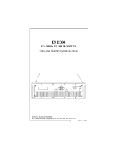
J1 MPX loopthrough
J12 Mono from left
J2 Right pre-emphasis
J4 Right Loud/Clarity
VR3-4 Limiter offset trim
J3 Left Pre-emphasis
J5 Left Loud/Clarity
J7 Left Lim. Clipper
J6 Right Lim. Clipper
J8 Limiter On/Off
J9 Left filter Clipper
J10 Right filter Clipper
VR6 Pilot level control
J11 Pilot On/Off (stereo)
2.5 MODES OF OPERATION
The transmitter is fully configurable and can be set up to support various modes of operation. The mode of opera-
tion is set by the configuration of the internal jumpers.
This chapter provides a guide to the various jumpers, followed by a brief description of the main modes of opera-
tion. The advanced setup procedure pages that follow provide a little more information on each mode as well as
providing some information on setting the equipment up accurately if you have access to some test equipment.
2.51 A guide to the jumpers
Main combo board

TX FM Transmitter technical manual page 14
Installation and setup
There are altogether twelve jumpers on the board which can be set - at the time of installation - to establish the way
the board operates.
The board leaves the factory with default settings which should be suitable for most locations and requirements.
Nevertheless, it is worth familiarizing yourself with all the options available, and checking that the settings are appro-
priate, as part of the installation process.
Jumper 1: MPX loopthrough
The default position is ON.
This is where you want the audio left and right XLR sockets on the back of the board to be the signal source,
duly limited and stereo coded internally. Only when you want to use the rear BNC socket for a complete mul-
tiplex (MPX) input for the broadcast should you change the position of this link.
If the link is in the OFF position, only signals from an external coder or processor will be accepted, unless the
internal coder has been ‘loop-throughed’ (see later).
Jumpers 2 and 3: Pre-emphasis 0 / 50 / 75uS
The default position is 50 uS (75 US/Japan).
What is pre-emphasis?
Pre-emphasis is the treble boost that must be applied to all FM broadcasts to compensate for the treble cut
(de-emphasis) present in every receiver. The aim of this process is to reduce noise in the broadcast path with-
out degrading the audio.
The precise nature of the treble boost is defined by a time-constant in microseconds, which describes the
resistor/capacitor network that will produce the appropriate 6dB per octave treble boost curve.
There are two different standards in use worldwide.
In Europe and Africa, the standard is normally 50uS. This represents a lift of about 3dB at 3 KHz, and
10dB at 10 KHz. In the Americas, and in Japan, more boost is in use with a network of 75uS, about 3dB
up at 2 KHz.
Jumpers 2 & 3 may either link the 50uS pins, the 75uS pins, or not link any pins, but be fixed to just one of
them for safekeeping, producing no pre-emphasis - ‘0’.
The effects of pre-emphasis
The absence of any pre-emphasis will result in a broadcast sounding noticeably lacking in treble. Applying
50uS pre-emphasis will correct the situation in European receivers (75uS in US/Japan). If you apply 75uS
pre-emphasis when 50 is called for, the received sound will have some 3dB shelved treble boost above 3KHz.
This is undesirable. Conversely, if you only apply 50 where 75 is required, there will be 3dB treble loss, which
is also undesirable. You should not have to change the pre-emphasis setting from 50 to 75 or back unless
you are relocating the installation abroad where the standard is different.
However, whenever pre-emphasis is deliberately applied to your audio at some point before it enters the XLR
sockets on the back of the board, by an external processor for example, then you must set the pre-emphasis
to ‘0’, because pre-emphasis must only be applied once. Double pre-emphasis must be avoided because it
will make a signal sound far too bright and toppy.
Both Jumper 2 and Jumper 3 should be in the same position at all times because both left and right audio
channels should have the same treatment. These jumpers do not affect the operation of the board when
external MPX is used with Jumper 1 off.
Jumpers 4 and 5: Limiter loud/pure
The default position is ‘Loud’ (hard limiting).

TX FM Transmitter technical manual page 15
Installation and setup
This option affects the character of the sound passing through the limiters inside the board. The sound can
be either (a) processed to be competitively loud, with some sacrifice in fidelity (hard limiting, the Loud posi-
tion) or (b) treated more gently, with high fidelity, but some loss in volume (soft limiting, the Pure position).
It’s instructive to listen to and compare the options while passing a representative selection of typical pro-
gramme material through the board. This will help you establish which sound you prefer.
As before, both jumpers 4 and 5 should always be in the same position. These jumpers, like all the following
ones, do not affect the operation of the board when external MPX is used with Jumper 1 off.
Jumpers 6 and 7: Limiter clippers on/off
The default position for these jumpers is ON.
If they are to be switched off when external audio processing is used, careful monitoring of deviation is rec-
ommended. The 15 KHz post-filter clippers must be switched off at the same time (J9/10).
These jumpers control the clippers applied to the signal after the limiter but before the 15KHz low-pass filters
on the way into the stereo coder. Again, these jumpers work as a pair and do not affect external MPX inputs.
Jumper 8: Limiter on/off
The default position for this jumper is ON, i.e. limiter active.
If you are using a pre-processed and limited signal and do not want the additional protection of the internal
limiters, their action can be disabled by putting Jumper 8 in the OFF position. This one jumper controls both
channels, because the gain-reduction control voltage (which this jumper disables) is common to left and right.
Even with the limiter disabled you may still wish to use the pre-filter clippers (J6/7) and post-filter clippers (see
below, J9/10) for protection. Always observe the deviation produced very carefully for excesses above 75
KHz if you ever remove the action of the limiter or clippers.
Jumpers 9 and 10: 15KHz filter clippers on/off
The default position for these clippers, placed after the 15KHz filters on the input to the coder, is ON.
These clippers protect against over-deviation caused by signals which ‘ring’ in the 15KHz filter, even after hav-
ing been caught by the clipper before the filter. With certain pre-processed and filtered inputs, however, they
may be switched out of circuit. But keep a close eye on the deviation.
Don’t have these clippers switched on unless you also have the limiter clippers active. Otherwise, your sig-
nal could go out of specification.
These jumpers work as a pair and don’t affect external MPX drives.
Jumper 11: Mono / Stereo
The default position is STEREO, pilot tone on.
This option allows you to remove or restore the stereo pilot tone, at a frequency of 19 KHz, normally sitting
at a level between 8 and 10% of total deviation.
It is this tone which alerts stereo FM receivers to the need to switch on their stereo decoders. The presence
of a pilot tone is all that is required for the ‘stereo’ beacon to light on a receiver. If no 19KHz tone is received,
the receiver will operate in mono. It will not decode any L-R information modulated on the 38 KHz subcarri-
er, even when it is still present.
To make sure that no 38 KHz energy is generated during mono operation even from stereo inputs, operate

TX FM Transmitter technical manual page 16
Installation and setup
jumper 12, the ‘bridge’ link (see below). This jumper does not affect the mono/stereo status of externally-
coded MPX inputs (J1 off).
Jumper 12: Mono bridge
The default position is OFF.
When the board is operating in mono, the bridge should be set to ON. This ensures that when the board is
operating in mono, no stereo information is broadcast, and that a mono drive to either left or right inputs, or
a stereo input applied simultaneously to L and R inputs, will produce proper summed mono operation and no
spurious 38KHz signals.
Modes of operation
Multiplex / broadband input.
The Internal stereo encoder and audio limiter are not used. Wideband modulation is fed into the rear panel
BNC multiplex input socket. Allows external processors, encoders and rebroadcast receivers to be plugged
straight into the transmitter.
JUMPERS. J1 (OFF), J2-12 (N/A)
Stereo with internal limiter. ( factory setting )
Left and Right audio are fed to the back panel balanced inputs and are pre-emphasized, peak limited, fil-
tered and then fed to the internal stereo encoder for multiplex generation. The multiplex signal is then fed
through to the exciter module and to the back panel multiplex output BNC socket. See loopthrough mode
below *
JUMPERS. J1 (ON), J2-3 (50 or 75), J4-5 (LOUD or CLARITY), J6-7 (ON), J8 (ON), J9-10 (ON), J11 (ST),
J12 (OFF)
Stereo with internal limiter disabled.
As the above stereo with limiter mode except the limiter section is disabled. This mode can be used when
you want an external limiter / processor to provide all the peak limiting and protection. Clippers at the out-
put of the limiter module can be left in or out subject to your requirements. See loopthrough below *
JUMPERS. J1 (ON), J2-3 (0 or 50 or 75), J4-5 (LOUD or CLARITY), J6-7 (ON or OFF), J8 (OFF), J9-10
(ON or OFF), J11 (ST), J12 (OFF)
Mono from two independent channels.
Essentially the same as the stereo with limiter mode except the stereo pilot is disabled which will enable
receivers to receive you in mono. See loopthrough mode below *
JUMPERS. J1 (ON), J2-3 (50 or 75), J4-5 (LOUD or CLARITY), J6-7 (ON), J8 (ON), J9-10 (ON), J11 (MO),
J12 (OFF)
Mono from one channel input.
You can provide one audio feed to the transmitter via the left balanced input. Setting the internal bridge
jumper J12 to ON will join the left and right audio signals internally to maintain the same volume from the
transmitter and forces the stereo encoder section to replicate true mono. See loopthrough mode below *
JUMPERS. J1 (ON), J2-3 (50 or 75), J4-5 (LOUD or CLARITY), J6-7 (ON), J8 (ON), J9-10 (ON), J11 (MO),
J12 (ON)
Other configurations

TX FM Transmitter technical manual page 17
Installation and setup
Other configurations can be set by setting the jumpers in certain ways. For example: Mono with limiter off.
We have illustrated what we feel to be the most popular options.
JUMPERS. To suit application
* Loopthrough mode
The transmitter has been provided with a multiplex output socket to present the output of the internal audio
stages to the outside world. This allows you to connect the signal from the internal limiter and stereo
encoder to an external piece of equipment before being reinjected back into the transmitter via the multiplex
input socket.
The most common application is for RDS encoders which nearly always have a loopthrough connection for
this purpose. Other applications include SCA generators and composite clippers. You will need to set the
internal jumper to off for external loopthrough. This is to stop the internal stereo encoder’s multiplex output
signal from being fed to the exciter section internally.
More information on loopthrough setup is provided at the end of the advanced setup procedure section

TX FM Transmitter technical manual page 18
Installation and setup
ADVANCED SETUP PROCEDURE
The front panel LCD metering is accurate enough to set up the transmitter in the absence of external test equip-
ment. If you have access to a modulation meter and RF power meter then substitute those for references to the
relevant LCD display menu.
You will most likely need the following pieces of test equipment:
Audio signal generator capable of -10dbu to +10dbu
Voltmeter
2.52 Multiplex input only.
Open the lid of the transmitter and make sure that jumper J1 on the main board is configured so that MPX
Loopthrough is OFF. This makes sure that the internal stereo encoder is not connected through to the modulator.
Connect your wideband audio source (processor, coder or rebroadcast receiver) to the multiplex input on the back
panel. Setup your external equipment for its correct output level making sure that it falls into the range of -6 to
+10 dbu. Adjust the multiplex input level control on the back panel for a peak deviation of +/- 75KHz. The peak
deviation can be shown on the LCD system.
The factory setting for the multiplex input level is +6dBu. This corresponds to the output level of our internal
stereo encoder module. We recommend feeding this level input to the multiplex input socket if it is available from
the external equipment.
2.53 Stereo with internal limiters.
The transmitter will come set to this mode and from factory with the following settings. Input Gain at maximum,
limiter active and in loud mode, limiter clippers on and 15KHz filter clippers on. This provides the loudest most
competitive settings available with the transmitter without using an external multiband processor to significantly
boost loudness.
The gain controls on the back panel control the input drive to the limiter module and can be set so that limiting
occurs for a given input level. Factory setting is at maximum to enable maximum compression / limiting so that a
loud commercial sound is obtained. You can reduce your input level to suit the amount of compression required.
The Limiter ON jumper is set so that the limiter is enabled. The limiter clippers are on to define the maximum out-
put from the limiter under any conditions. The Limiter has two modes of limiting, Loud and Clarity. Loud will give a
more processed brighter sound and Clarity will retain a sound more true to the original audio input. If you want a
more punchy commercial sound leave the limiter in Loud mode. The 15KHz filters have overshoot clippers after
them. These if activated remove any overshoots caused by ringing in the filters. These are best left active if you
want the loudest sound for a peak deviation of +/- 75 KHz. (See note on 15KHz filters at the end of the section)
Advanced setup procedure.
1. Firstly make sure that the exciter is set to your chosen operating frequency. If you have not already done so
then remove the top cover from the transmitter.
2. Connect the transmitter to a dummy load.
3. Turn on the transmitter and within 15 seconds it should lock to frequency.
4. Set the internal limiter to OFF with jumper J8. Set the limiter clippers to ON with jumpers J6 and J7. Set the
15KHz filter clipper jumpers J9 and J10 to ON. Remove the pre-emphasis jumpers from J2 and J3 completely for
now. Make sure the loopthrough jumper J1 is switched to LOOPTHROUGH and the MONO FROM LEFT jumper
J12 is set to the OFF position. Disable the stereo pilot by setting jumper J11 to MONO. Set the limiter mode
jumper J4 and J5 to LOUD.
These settings will allow any audio straight through the limiter and into the limiter clippers that set our final peak
level.

TX FM Transmitter technical manual page 19
Installation and setup
5. We should check that any offsets internal to the limiter are nulled out to keep distortion to a minimum. Connect
a multimeter set to millivolts to testpoint TP1 which is located next to the right clipper jumper. You will also need
an earth point for the meter. The bolt on REG2 is a good earth. The case of the transmitter is not a good earth
due to the allo-chrome finish on the case. Adjust the blue multiturn pot VR3 in the center of the limiter section for
the minimum voltage reading on the meter. Aim for below 10 millivolts. Repeat for the left channel with VR4 and
by taking the reading from test point TP2.
6. Connect an audio source to both channels and apply a 400hz tone with a level of +6 dbu. Make sure the gain
controls are set to maximum (Fully clockwise). These are multiturn so make sure you hear / feel the pots click
indicating end of travel.
7. Work out the the pilot level you intend to use. It is usually between 8 and 10 percent of the modulation with 9
percent being standard in most countries. 9 percent corresponds to 6.75 KHz deviation so for a total peak devia-
tion of 75 KHz (the industry standard for 100 percent modulation) we need to adjust the multiplex level for a peak
deviation of 68.25 KHz (91 percent modulation). This corresponds to the total minus the intended pilot level that
we will re-introduce in a moment. We recommend further backing off the deviation by 4 % which equates to 3
KHz deviation. This 4 % acts as a guard-band for any small overshoots that may occur in the limiter and the
stereo encoder filters. You should at this point with your tones applied have a peak deviation of 75 KHz - 6.75KHz
(or intended pilot level) - 3 KHz = 65.25KHz. If you have not already done so, adjust the multiplex input level on
the back panel to this level. If you are using the LCD display metering then 65 KHz would be an acceptable set-
ting.
8. Reinstate the pilot by setting jumper J11 to stereo. Now adjust the pilot level control VR6 for a peak deviation of
The previous setting plus the intended pilot level. In our example this would mean setting the deviation at 72KHz.
This equates to our modulation and pilot leaving 3 KHz for our guard-band.
9. Set the limiter to ON with jumper J8. Decide on Clarity or loud mode for the limiter and set jumpers J4 and J5
accordingly.
The transmitter should now have the multiplex and pilot setup at the correct level. All that is left to do is to set the
input gain controls to your desired settings. For most applications where you require a compressed loud competi-
tive sound we recommend setting the gain controls at maximum. But if you are supplying a very high level feed
you may have to turn the gain controls down to stop internal clipping occurring prior to the limiter. (Please see
note on pre-emphasis at the end of the section). You may also wish the limiter to start to limit for a given level of
input. To set the limiters input controls up for a given input level consult step 10. Otherwise leave the input gain
controls at maximum and skip to step 12.
10. Apply your audio feed to the left channel input socket on the rear panel at the desired level you want limiting
to commence. This will need to be a minimum of 0dbu. The limiter inputs will need at least a 0dbu input to
achieve limiting even with the rear panel gain controls set at maximum. Read the pre-emphasis note at the end of
the section for more info on input level restrictions.
Set the LCD display to limiter gain reduction and with audio applied to the left channel reduce the left channel
input gain control until the display flickers from 0dB to 2dB gain reduction.This is the onset of limiting.
11. Remove the left channel audio and repeat the procedure for the right channel. This procedure also ensures
that both inputs to the internal limiter are driven equally.
12. Set the pre-emphasis jumpers J2 and J3 to the correct setting for your region, 75uS for the Americas and
Japan and 50uS for the rest of the world. If your audio feed has gone through an external processor prior to this
transmitter then check to see if that unit has pre-emphasis capability and if it is switched on. If it has pre-empha-
sis and it is enabled then you should remove the pre-emphasis jumpers J2 and J3 to ensure that only one set of
pre-emphasis has been applied throughout the broadcast chain.
13. Connect your studio feed to the transmitter. Turn the power off to the transmitter, connect your external
antenna, reconnect the power and you’re on the air!
14. Monitor your total peak deviation with your real world audio material and check with the deviation display that
your peak deviation does not exceed 75 KHz. If you have set up the transmitter as per the instructions in this sec-
tion then you should be within 1 KHz or so of this figure. If your deviation does exceed 75 KHz then adjust the
back panel multiplex control to keep your maximum deviation at 75 KHz.

TX FM Transmitter technical manual page 20
Installation and setup
2.54 Stereo with internal limiters disabled.
The limiter can be disabled internally if you do not require it. This effectively allows any audio input signals
straight through to the stereo encoder unaltered. You may wish to disable the limiter when you have an external
processor or limiter that may be of a higher performance than the internal limiter in this transmitter. You can still
have the limiter active even with external limiters in operation, as the limiter will not discolor the sound when fed
with pre-processed audio. We leave that up to you. For safety purposes you may wish to leave the clippers on the
limiter and the 15KHz filters in to provide extra protection when you are unsure of the peak output characteristics
of the external piece of equipment. When you know that the piece of audio processing equipment is band-limited
to 15KHz and peak limited you can leave out the clippers safe in the assumption that the external processor will
be able to handle the level control completely.
Advanced setup procedure.
1. Firstly make sure that the exciter is set to your chosen operating frequency. If you have not already done so
then remove the top cover from the transmitter.
2. Connect the transmitter to a dummy load.
3. Turn on the transmitter and within 15 seconds it should lock to frequency.
4. Set the internal limiter to OFF with jumper J8. Set the limiter clippers to ON with jumpers J6 and J7. Set the
15KHz filter clipper jumpers J9 and J10 to ON. Remove the pre-emphasis jumpers from J2 and J3 completely for
now. Make sure the loopthrough jumper J1 is switched to loopthrough and the mono from left jumper J12 is set to
the OFF position. Disable the stereo pilot by setting jumper J11 to mono. Set the limiter mode jumper J4 and J5 to
CLARITY
These settings will allow any audio straight through the limiter and into the stereo encoder without any form of
level control apart from the peak level clippers, so we can set the system internal levels correctly.
5. We should check that any offsets internal to the limiter are nulled out to keep distortion to a minimum. Connect
a multimeter set to millivolts to testpoint TP1 which is located next to the right clipper jumper. You will also need
an earth point for the meter. The bolt on REG2 is a good earth. The case of the transmitter is not a good earth
due to the allo-chrome finish on the case. Adjust the blue multiturn pot VR3 in the center of the limiter section for
the minimum voltage reading on the meter. Aim for below 10 millivolts. Repeat for the left channel with VR4 and
by taking the reading from test point TP2.
6. Connect an audio source to both channels and apply a 400Hz tone with a level of +6dBu. Make sure the gain
controls are set to maximum (Fully clockwise). These are multi-turn so make sure you hear / feel the pots click
indicating end of travel.
7. Work out the the pilot level you intend to use. It is usually between 8 and 10 percent of the modulation with 9
percent being standard in most countries. 9 percent corresponds to 6.75 KHz deviation so for a total peak devia-
tion of 75 KHz (the industry standard for 100 percent modulation) we need to adjust the multiplex level for a peak
deviation of 68.25 KHz (91 percent modulation). This corresponds to the total minus the intended pilot level that
we will re-introduce in a moment. We recommend further backing off the deviation by 4 % which equates to 3
KHz deviation. This 4 % acts as a guard-band for any small overshoots that may occur in the limiter and the
stereo encoder filters. You should at this point with your tones applied have a peak deviation of 75 KHz - 6.75KHz
(or intended pilot level) - 3 KHz = 65.25KHz. If you have not already done so, adjust the multiplex input level on
the back panel to this level. If you are using the LCD display metering then 65 KHz would be an acceptable set-
ting.
8. Re-instate the pilot by setting jumper J11 to STEREO. Now adjust the pilot level control VR6 for a peak devia-
tion of 75KHz peak deviation (100 percent modulation)
/