
Description
e LightHAWK is an intelligent self-adapting occupancy sensor that is
designed to replace existing wall switches.
Specifi cations
• 1000 sq. ft coverage area (Models: LHIR and LHMT)
• 400 sq. ft. coverage area (Models: LHUS)
• Single or Dual circuit 120/277VAC, 50/60Hz operation
• Electrical Ratings: (Each Output Separately)
120VAC – 800W Incandescent, 1000W Ballast, 1/6 HP
277VAC – 1800W Ballast, 1/6 HP
• Adjustable Time Delay: 4-30 minutes, self-adapts based
on occupancy
• Light Level Adjustment (Circuit B output on Dual Circuit versions):
10-500+FC
• ETL listed (Conforms to UL STD 508 Certifi ed to CAN/CSA STD
C22.2 No. 14)
Precautions
CAUTION: RISK OF ELECTRICAL SHOCK. Turn power off at
service panel before beginning installation. Never wire energized electrical
components.
Read and understand all instructions before beginning installation.
NOTICE: For installation by a licensed electrician in accordance with
National and/or local Electrical Codes and the following instructions.
NOTICE: For indoor use only.
CAUTION: USE COPPER CONDUCTOR ONLY.
Confi rm that device ratings are suitable for application prior to installation.
NOTICE: Do not install if any damage to product is noticed.
Installation
1. Turn power off at the service panel.
2. Remove the old switch(es) if applicable.
3. Wire as shown in the Wiring Diagram section. A secure connection
to ground is necessary for the sensor to function properly.
4. Install sensor in wall box using mounting screws provided.
5. Restore power to the sensor and allow it to warm up (up to 2 min.).
6. Remove the sensor’s cover – see Adjustments section.
7. If desired, calibrate the photocell sensor and adjust the sensor’s
confi guration switch settings as described below.
8. Reinstall the sensor’s cover.
9. Install a Decorator style wall plate (not included).
Test Mode – to enter test mode:
1. Make sure lights are on.
LightHawk
™
Wall Switch Occupancy Sensors
Installation and Operating Instructions
Hubbell Building Automation, Inc.
9601 Dessau Road, Building One, Suite 100
Austin, Texas 78754
512-450-1100 • 512-450-1215 Fax
www.hubbell-automation.com
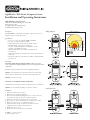
Wiring Diagram
Sensor Operation
Range Diagram

2. Press and hold the ON/OFF button until the lights cycle off then back
on. For dual circuit sensors, press and hold the ON/OFF button for
Circuit A. For No-button sensors, press and hold the Test Button.
See Sensor Operation Diagram.
3. Sensor is now in test mode. Vacate room, lights should turn off after
5 seconds. Step back into room (sensing zone), lights will turn back
on. Repeat as necessary to confi rm sensor is operating and detecting
in the lighting zone as desired. Sensor will fl ash red or green LED to
indicate Passive Infrared or Ultrasonic occupancy detection as applicable.
4. To exit Test Mode, press any button. Note: Sensor will automatically
exit Test Mode after 1 hour.
Manual Override – Press button(s) to place sensor in manual mode. Lights
will turn off and remain off while occupancy is detected. Sensor will return
to automatic mode when button is pressed again to turn lights on or when
the sensor’s timer value is reached. Note: No-button sensors cannot be
manually turned off .
Air-Gap Override – If it is necessary to service the controlled circuits
without de-energizing them at the breaker panel (this is not recommended
as a standard procedure):
1. Remove the sensor’s cover plate (see Adjustments section).
2. With the circuit(s) on, turn the air-gap switch to OFF
(toward the outside of the sensor).
3. Push the button(s) to turn the circuit(s) OFF.
4. Push the button(s) again to verify override.
e air-gap switch will now interrupt sensor operation, preventing
output(s) from turning on again, regardless of occupancy or pushbutton
conditions. To return the sensor to normal operation, fl ip the air-gap
switch to the ON position and push the button(s) to return the circuit(s) to
Automatic mode. Re-install the sensor cover. Note: Sensor cover cannot be
re-installed unless the air-gap switch is in the ON position.
Adjustments
Open the sensor cover by inserting a small blade screwdriver into the
catch at the bottom of the sensor and gently snap the cover loose. Set the
adjustment switches as desired (see Confi guration Switch Settings below).
To re-install cover, insert catches at top of cover into recesses in sensor
housing and gently snap cover into catch at bottom of housing.
Photocell
e photocell is used to detect if other light sources such as sunlight, are
enough to illuminate the space without turning on the lights. For Dual
Circuit versions, only Circuit B is controlled by the photocell. e sensor is
shipped from the factory with the photocell control disabled. If use of the
photocell is desired, calibrate the photocell set points as follows:
1. Remove the sensor’s cover plate.
2. With the sunlight at the desired level where the lights should turn on,
press the photocell button.
3. Step back from the sensor to avoid changing ambient light levels in the
room. Note: During calibration the sensor will turn the lights off
and on.
4. After the calibration process is complete (approx. 3 min.), reinstall
sensor cover.
Confi guration Switch Settings
Note: e sensor is shipped with all switches in the factory default (off )
condition (switches positioned toward edge of sensor).
Switch 1 – Auto/Manual
Controls selection between Auto ON/Auto OFF Mode and Manual ON/
Auto OFF Mode. For Dual Circuit versions, this switch controls Auto/
Manual Mode for Circuit A only.
Switch 2 – Auto/Manual B (Dual Circuit Versions Only)
Controls selection between Auto ON/Auto OFF Mode and Manual ON/
Auto OFF Mode for Circuit B.
Switch 3 – Photocell Mode
Controls selection between One Way Mode and Continuous Mode. In
One Way Mode, the sensor turns lights on in response to occupancy
when light levels are below the photocell set point then maintains them
in the on condition regardless of light level. In Continuous Mode, the
sensor functions the same as One Way Mode, except that during periods
of occupancy it will turn the lights off if ambient light levels increase
suffi ciently to illuminate the space. Note: For Dual Circuit versions, the
photocell controls the operation of Circuit B only.
Switches 4 and 5 – Timer 1 and Timer 0
Use to set the initial timer value that the sensor will maintain lights on
without detecting occupancy. See Auto/Fixed Timer below for additional
information.
Switch 6 – Auto/Fixed Timer
Controls selection between Adaptive Timer Mode and Fixed Timer Mode.
In Automatic Adaptive Timer Mode, the sensor will use the timer interval
setting from switches Timer 0 and Timer 1 above. It will then begin
adjusting it’s timer settings as appropriate for the lighted space to optimize
performance based on occupancy patterns. In Fixed Timer Mode, the
sensor’s self-adapting timer functions are disabled and the sensor maintains
the lights in the space according to the switch settings of Timer 0 and
Timer 1.
Switch 7 – Hallway
Disables or enables the sensor’s hallway algorithm. When enabled, this
feature reduces false tripping of the lights associated with hallway traffi c
outside the room where the sensor is controlling the lights. is feature
should be enabled when the sensor is installed facing toward the entryway
into the room and sensor’s range of detection extends into a hallway or
adjoining areas with occupancy.
Switch 8 – Adaptive Reset
When toggled on then off , this switch resets the sensor’s adaptive timer
and sensitivity settings. e adaptive timer is reset according to Timer 0
and Timer 1 above. e adaptive sensitivity (both PIR and Ultrasonic as
applicable) are reset to factory default. e Photocell Sensor is also reset
to factory default (disabled) such that the sensor will turn on the light(s) in
response to occupancy regardless of ambient light levels in the lighted space.
Hubbell Building Automation, Inc.
9601 Dessau Road • Austin, Texas 78754
512-450-1100 • 512-450-1215 Fax • www.hubbell-automation.com
72-00358 revB/hba.wall.lhmtd.1/2006.1
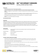
Switch Settings (as seen on front of sensor)
Switch
Function
8 Sensitivity/Timer/Photocell Enable Adaptation Restore Factory Defaults
7 Hallway Mode Disable Enable
6 Timer Mode Automatic Fixed
5 Timer Select 1 <--- <---
4 Timer Select 0 <--- <---
3 Photocell Control Mode One Way Continuous 4 min 8 min 15 min 30 min
2 Relay Override B Automatic Manual
1 Relay Override A Automatic Manual
switch toggle direction
-
 1
1
-
 2
2


Ask a question and I''ll find the answer in the document
Finding information in a document is now easier with AI
Other documents
-
Hubbell Wiring Device-Kellems RCSPOR Installation guide
-
Hubbell CLT1554 User manual
-
-
Leviton OSD10-I0W User manual
-
 Hubbell Control Solutions NX Vacancy/Occupancy Sensor Installation guide
-
-
Crestron GLS-ODT-C-500 User guide
-
-
-
