Page is loading ...

g
GE Capacitor & Power Quality Product
s
MATRIX FILTER
SERIES B
480 Volts, 60HZ
USER MANUAL

g
GE Capacitor & Power Quality Product
s
IMPORTANT USER INFORMATION
NOTICE
The GE Corporation Matrix Filter is designed for harmonic mitigation of six pulse
inverter drives supplying variable torque loads in a wide variety of applications. The
suitability of this filter for a specific application must therefore be determined by the
customer. In no event will GE assume responsibility or liability for any direct or
consequential damages resulting from the use or application of this filter. Nor will GE
assume patent liability with respect to the use of information, circuits or equipment
described in this instruction manual.

g
GE Capacitor & Power Quality Product
s
TABLE OF CONTENTS
1. Safety .......................................................................................................... 1
2. Introduction ................................................................................................. 3
3. Model Number Codes.................................................................................. 4
4. Specifications .............................................................................................. 5
Ratings .................................................................................................. 5
Service Conditions ................................................................................. 5
Performance ......................................................................................... 6
Altitude Derating Curve ........................................................................ 11
5. Installation Instructions .............................................................................. 12
Filter Installation ................................................................................... 12
Outline Drawings and Mounting Dimensions ....................................... 13
Power Wiring Connection .................................................................... 29
Ground and Ground Fault Protection................................................... 29
Input and Output Terminal Specifications ............................................ 30
Interconnection Diagrams.................................................................... 31
6. Filter Description ....................................................................................... 44
7. Start – Up .................................................................................................. 46
8. Troubleshooting......................................................................................... 48

GEH-7252 1 May 2003
g
GE Capacitor & Power Quality Product
s
1. IMPORTANT SAFETY INFORMATION
WARNING
ONLY A QUALIFIED ELECTRICIAN CAN CARRY OUT THE ELECTRICAL
INSTALLATION OF THIS FILTER
WARNING
High voltage is used in the operation of this filter. Use Extreme caution to avoid contact with
high voltage when operating, installing or repairing this filter. INJURY, DEATH AND/OR
PROPERTY DAMAGE MAY RESULT IF SAFETY PRECAUTIONS ARE NOT
OBSERVED.
After removing power, allow at least five minutes to elapse and verify that the capacitors
have discharged to a safe level before contacting internal components. Connect a DC
voltmeter across the capacitor terminals or terminals 1, 2 and 3 on terminal block 1TB.
Start with the meter on the highest scale and progressively switch to a lower scale as the
indicated voltage falls below the maximum value of the scale used.
WARNING
THE OPENING OF THE BRANCH CIRCUIT PROTECTIVE DEVICE MAY BE AN INDICATION THAT A
FAULT CURRENT HAS BEEN INTERRUPTED. TO REDUCE THE RISK OF FIRE OR ELECTRICAL
SHOCK, CURRENT-CARRYING PARTS AND OTHER COMPONENTS OF THE FILTER SHOULD BE
EXAMINED AND REPLACED IF DAMAGED.
WARNING
AN UPSTREAM DISCONNECT/PROTECTION DEVICE MUST BE USED AS REQUIRED BY THE
NATIONAL ELECTRICAL CODE (NEC).
WARNING
EVEN IF THE UPSTREAM DISCONNECT/ PROTECTION DEVICE IS OPEN, THE DRIVE DOWN
STREAM OF THE FILTER MAY FEED BACK HIGH VOLTAGE TO THE FILTER. THE DRIVE
SAFETY INSTRUCTIONS MUST BE FOLLOWED.
INJURY, DEATH AND/OR PROPERTY DAMAGE MAY RESULT IF THE DRIVE SAFETY
PRECAUTIONS ARE NOT OBSERVED.
WARNING
THE FILTER MUST BE GROUNDED WITH A GROUNDING CONDUCTOR CONNECTED TO
ALL GROUNDING TERMINALS

GEH-7252 2 May 2003
g
GE Capacitor & Power Quality Product
s
WARNING
ONLY SPARE PARTS OBTAINED FROM GE OR AN AUTHORIZED GE DISTRIBUTOR CAN BE
USED.

GEH-7252 3 May 2003
g
GE Capacitor & Power Quality Product
s
2. INTRODUCTION
This manual was specifically developed to
assist in the installation, interconnection and
operation of the GE Matrix Filter.
This manual is intended for use by personnel
experienced in the operation and maintenance
of electronic drives. Because of the high
voltages required by the filter and drive and
the potential dangers presented by rotating
machinery, it is essential that all personnel
involved in the operation and maintenance of
this filter know and practice the necessary
safety precautions for this type of equipment.
Personnel should read and understand the
instructions contained in this manual before
installing, operating or servicing the filter and
the drive to which the filter is connected.
Upon Receipt of this Filter:
The GE Matrix Filter has been subjected to
demanding factory tests before shipment.
Carefully inspect the shipping container for
damage that may have occurred in transit.
Then unpack the filter and carefully inspect for
any signs of damage. Save the shipping
container for future transport of the filter.
In the event of damage, please contact and
file a claim with the freight carrier involved
immediately.
If the equipment is not going to be put into
service upon receipt, cover and store the filter
in a clean, dry location. After storage, ensure
that the equipment is dry and that no
condensation has accumulated on the internal
components of the filter before applying
power.
Repair/Exchange Procedure
GE requires a Returned Material Authorization
Number before it can accept any filters that
qualify for return or repair. If problems or
questions arise during installation, setup, or
operation of the filter, please call us for
assistance at:
Phone: 518-746-5793
FAX: 518-746-5524

GEH-7252 4 May 2003
g
GE Capacitor & Po
w
er Quality Product
s
3. MODEL NUMBER CODES
37GM (5 or 8) X X X X X X X X X X X
Total Harmonic Current Distortion (THID)
5% or 8% THID
Mechanical Configuration
G = General Purpose NEMA 1 & 2
W= General Purpose NEMA 3R
N = Industrial Style NEMA 1
Enclosure Size
B CAB 17B or CAB-002
C CAB 20B or CAB-003
D CAB 30B or CAB-004
E CAB 42B or CAB-005
F CAB-006
Output Current Rating
(i.e., 0044 is 44 amps)
Voltage and Frequency
A 208-240V, 60Hz
B 240V, 50Hz
C 380-415V, 50Hz
D 480V, 60Hz
E 600V, 60Hz
Options
Matrix Filter Designator

GEH-7252 5 May 2003
g
GE Capacitor & Po
w
er Quality Product
s
4. SPECIFICATIONS
Ratings
Table 1
480 VAC, 60 Hz SERIES B Filter Ratings
THID Rating 8% 5%
Maximum
Output Amps
RMS
Efficiency
(Typical)
(%)
Power Dissipation
@ Rated Current
(Typical)
(Watts)
Efficiency
(Typical)
(%)
Power Dissipation
@ Rated Current
(Typical)
(Watts)
6 97.2 139 97.4 132
8 97.5 164 97.6 161
11 97.8 200 97.8 197
14 98.0 233 98.0 232
21 98.3 299 98.3 294
27 98.4 351 98.5 343
34 98.6 406 98.6 399
44 98.7 479 98.7 472
52 98.8 539 98.8 533
66 98.9 626 98.9 621
83 98.9 740 98.9 735
103 99.0 850 99.0 844
128 99.1 964 99.1 959
165 99.2 1143 99.2 1145
208 99.2 1355 99.2 1361
240 99.3 1493 99.2 1498
320 99.3 1829 99.3 1838
403 99.4 2110 99.4 2098
482 99.4 2393 99.4 2371
636 99.4 2978 99.4 2929
786 99.5 3432 99.5 3402
Service Conditions
Load: 6 pulse variable torque rectifier only
Input voltage: 480 VAC +/- 10%, 60 +
0.75 Hz, 3 phase
Input voltage line unbalance: 1% maximum
Maximum source impedance: 6.00%
Minimum source impedance: 1.5%
Service Factor: 1.00

SPECIFICATIONS - continued
GEH-7252 6 May 2003
g
GE Capacitor & Power Quality Product
s
Ambient Temperature (Operating)
Enclosed Filters: -40 to +40 degrees C
Open Panel Filters: -40 to +50 degrees C
Storage Temperature: -40 to +90 degrees C
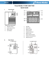
Altitude: 0 to 3300 Feet above sea level. Refer to Figure 6 for altitude derating.
Relative Humidity: 0 to 95% non-condensing
Agency Approvals
UL-508C File E191686 Component Recognized
(3-1000 HP, 120 VAC through 600 VAC
50, 50/60, 60 Hz Three Phases
CAN/CSA C22, 2 No. 14-95
Performance
Total Harmonic Current Distortion:
Eight Percent Filter: 8% typical at full load 12% maximum no load to full load
Five Percent Filter: 5% typical at full load 8% maximum no load to full load
Standby Current:
Without Optional Capacitor Contactor: 70% of the full load capacitor current listed in Table 3
With Optional Capacitor Contactor: Refer to Drive Users Manual
8% Filter Voltage Regulation with nominal 480 volts RMS source
Maximum output voltage at no load: 502 volts RMS, 710 volts peak
Maximum PCC* voltage with 6.00% source impedance at no load: 490 volts RMS, 693 volts peak
Minimum output voltage at full load: 460 volts RMS, 600 volts peak
5% Filter Voltage Regulation with nominal 480 volts RMS source
Maximum output voltage at no load: 502 volts RMS, 710 volts peak
Maximum PCC voltage with 6.00% source impedance at no load: 490 volts RMS, 693 volts peak
Minimum output voltage at full load: 460 volts RMS, 600 volts peak
*Note: PCC is the point of common coupling with the power distribution system

SPECIFICATIONS - continued
GEH-7252 7 May 2003
g
GE Capacitor & Power Quality Product
s
Table 2
480 Volt, 60 Hz Series B Matrix Filter
Weights
Open Panel
General Purpose
NEMA 1, 2, 3R
Industrial
NEMA 1
THID THID THID
Output
Amps RMS
8%
Weight Lbs
5%
Weight Lbs
8%
Weight Lbs
5%
Weight Lbs
8%
Weight Lbs
5%
Weight Lbs
6 273883946273
8 304085966575
11 35 45 95 105 70 80
14 35 45 95 105 80 90
21 45 60 105 120 85 100
27 50 65 135 150 100 115
34 70 85 160 175 125 140
44 70 85 160 175 125 140
52 105 135 170 200 235 265
66 125 155 300 330 270 300
83 200 250 355 405 325 375
103 200 250 355 405 325 375
128 225 275 385 435 350 400
165 265 325 420 480 475 535
208 275 325 425 475 485 535
240 300 400 500 600 525 625
320 650 750 740 840 1175 ---
403 700 825 830 955 1250 ---
482 775 930 890 1045 1350 ---
636 --- --- 1200 1450 --- ---
786 --- --- 1400 1700 --- ---

SPECIFICATIONS - continued
GEH-7252 8 May 2003
g
GE Capacitor & Power Quality Product
s
Table 3
480 VAC Matrix Filters
Capacitor Current at Full Load
Filter
Current
Rating
Amps
Rms
Capacitor
Current
(Typical)
Amps
RMS
Filter
Current
Rating
Amps
Rms
Capacitor
Current
(Typical)
Amps
RMS
Filter
Current
Rating
Amps
Rms
Capacitor
Current
(Typical)
Amps
RMS
6 2.0 44 145 208 79.7
8 2.7 52 20.7 240 93.1
11 3.9 66 21.5 320 124.8
14 5.4 83 31.5 403 156.0
21 7.1 103 33.6 482 188.9
22 10.7 128 39.3 636 246.4
34 13.1 165 56.4 786 303.4
Figure 1
8% Filter THID vs. Load
0
2
4
6
8
10
12
0 20406080100
Percent Load
Percent THID
Typical Worst Case
Figure 2
5% Filter THID vs. Load
0
1
2
3
4
5
6
7
8
9
0 20406080100
Percent Load
Percent THID
Typical Worst Case

SPECIFICATIONS - continued
GEH-7252 9 May 2003
g
GE Capacitor & Power Quality Product
s
Figure 3
8% Matrix Filter Harmonic Spectrum
100% Load
0.0
0.5
1.0
1.5
2.0
2.5
3.0
3.5
4.0
4.5
1 3 5 7 9 11 13 15 17 19 21 23 25
Harmonic order
Harmonic Current, %
Typical Worst Case
Figure 4
5% Matrix Filter Harmonic Spectrum
100% Load
0.0
0.5
1.0
1.5
2.0
2.5
3.0
3.5
1 3 5 7 9 11 13 15 17 19 21 23 25
Harmonic order
Harmonic Current, %
Typical Worst Case

SPECIFICATIONS - continued
GEH-7252 10 May 2003
g
GE Capacitor & Power Quality Product
s
Figure 5
5% and 8% Filter Power Factor vs Load
Leading PF For All Load
0.20
0.30
0.40
0.50
0.60
0.70
0.80
0.90
1.00
1.10
0 20406080100120
Percent Filter Load
Power Factor
Typical Worst Case
Performance With Unbalanced Line Voltage (Typical)
Table 4
All Components at Nominal Values
and Worse Case Service Conditions
8% Filter 100% Load 5% Filter 100% Load
Nominal THID 5.12% 3.93%
1% Unbalance 5.28% 4.06%
2% Unbalance 5.82% 4.47%
3% Unbalance 6.62% 5.10%
8% Filter 30% Load 5% Filter 30% Load
Nominal THID 10.13% 7.06%
1% Unbalance 10.61% 7.45%
2% Unbalance 12.11% 8.21%
3% Unbalance 14.30% 10.46%

SPECIFICATIONS - continued
GEH-7252 11 May 2003
g
GE Capacitor & Power Quality Product
s
Figure 6
Altitude Derating Curve
1.05
1.00
0.95
0.90
0.85
0.80
0.75
0.70
0 3300 6600 9900 13200 16500
CURRENT DERATING FACTOR
ALTITUDE (FEET)

GEH-7252 12 May 2003
g
GE Capacitor & Power Quality Product
s
5. INSTALLATION INSTRUCTIONS
Filter Installation
Matrix Filters are supplied in the following
mechanical configurations:
Panel mounted assemblies
Floor mounted general purpose NEMA 1, 2,
& 3R cabinets
Industrial style NEMA 1 cabinets with
hinged doors.
Panel mounted filters are designed for
mounting in the vertical plane in the customer’s
enclosure. Include the power dissipation of the
filter along with all the other components
located in the panel to determine the internal
temperature rise and cooling requirements of
the enclosure. Allow a minimum side clearance
of four (4) inches and a vertical clearance of
six (6) inches for proper heat dissipation and
access. Figure 7 through Figure 15 contain
outline drawings for the various ratings and
show proper mounting orientation. For 5%
filters, Model numbers beginning with 37GM5,
refer to Figure 15 and Table 5 for the
dimensions of the separately mounted input
reactor.
Select a well ventilated, dust-free area away
from direct sunlight, rain or moisture. Do not
install in or near a corrosive environment.
Avoid locations where the filter would be
subjected to excessive vibrations.
General purpose NEMA 1, 2, and 3R enclosed
filters are designed for floor mounting in the
vertical plane in an environment suitable for
the enclosure type. Do not install in or near a
corrosive environment. Avoid locations where
the filter would be subjected to excessive
vibrations. Allow a minimum side and back
clearance of eight (8) inches and front
clearance of thirty-six (36) inches for proper
heat dissipation and access. Table 6 will direct
you to the appropriate outline drawings shown
in Figure 16 through Figure 19.
Industrial style NEMA 1 enclosed filters are
designed for wall and floor mounting in the
vertical plane. Do not install in or near a
corrosive environment. Avoid locations where
the filter would be subjected to excessive
vibrations. For wall mounted enclosures allow
a minimum side clearance of eight (8) inches
and front clearance of forty-eight (48) inches
for proper heat dissipation and access. For
floor mounted enclosures allow a minimum
side and back clearance of eight (8) inches
and front clearance of forty-eight (48) inches
for proper heat dissipation and access. Table
7
will direct you to the appropriate outline
drawings shown in
Figure
20 through
Figure 24.

INSTALLATION INSTRUCTIONS - continued
GEH-7252 13 May 2003
g
GE Capacitor & Power Quality Product
s
Mounting Dimensions And Outline Drawings For Panel Mounted Filters Follow
Figure 7
6 – 21 Amps, 480 VAC 60Hz Outline Drawing
All dimensions are in inches

INSTALLATION INSTRUCTIONS - continued
GEH-7252 14 May 2003
g
GE Capacitor & Power Quality Product
s
Figure 8
27 Amps, 480 VAC 60Hz Outline Drawing
All dimensions are in inches

INSTALLATION INSTRUCTIONS - continued
GEH-7252 15 May 2003
g
GE Capacitor & Power Quality Product
s
Figure 9
34 – 44 Amps, 480 VAC 60Hz Outline Drawing
All dimensions are in inches

INSTALLATION INSTRUCTIONS - continued
GEH-7252 16 May 2003
g
GE Capacitor & Power Quality Product
s
Figure 10
52 - 66 Amps, 480 VAC 60Hz Outline Drawing
All dimensions are in inches
REACTOR ASSEMBLY
CAPACITOR ASSEMBLY

INSTALLATION INSTRUCTIONS - continued
GEH-7252 17 May 2003
g
GE Capacitor & Power Quality Product
s
NOTE: CAPACITOR ASSEMBLY MAY BE MOUNTED IN EITHER PLANE
Figure 11
83 – 128 Amps, 480 VAC 60Hz Outline Drawing
All dimensions are in inches
REACTOR ASSEMBLY
CAPACITOR ASSEMBLY
/