Page is loading ...

Instructions-Parts
E-Flo® E-Flo®
E-Flo®
DC DC
DC
4–Ball 4–Ball
4–Ball
Piston Piston
Piston
Pumps Pumps
Pumps
3A2096D
EN
Electric Electric
Electric
drive drive
drive
piston piston
piston
pumps pumps
pumps
for for
for
low low
low
to to
to
medium medium
medium
volume volume
volume
paint paint
paint
circulation circulation
circulation
applications. applications.
applications.
For For
For
professional professional
professional
use use
use
only. only.
only.
Important Important
Important
Safety Safety
Safety
Instructions Instructions
Instructions
Readallwarningsandinstructionsinthismanual.
Save Save
Save
these these
these
instructions. instructions.
instructions.
See Technical Data, page 29, for
Maximum Working Pressure.
See page 3 for model part numbers and
approvals information.
PROVENQUALITY.LEADINGTECHNOLOGY.

Contents Contents
Contents
Models...............................................................3
RelatedManuals................................................3
Warnings...........................................................4
Installation..........................................................8
Location......................................................8
MountthePump..........................................8
PowerSupplyRequirements.........................8
ConnectthePowerSupply...........................10
Grounding...................................................11
FluidLineAccessories.................................12
FillWithOilBeforeUsingEquipment.............12
FlushBeforeUsingEquipment......................12
ControlModuleAccessory............................12
Operation...........................................................13
Startup........................................................13
Shutdown....................................................13
PressureReliefProcedure............................13
Maintenance......................................................14
PreventiveMaintenanceSchedule................14
ChangetheOil.............................................14
CheckOilLevel...........................................14
BearingPre-Load.........................................14
Flushing......................................................14
Troubleshooting..................................................15
Repair................................................................16
Disassembly................................................16
Reassembly................................................16
ReassembletheCouplingAdapterandTie
RodstotheMotor...........................17
Parts..................................................................18
PumpAssembly...........................................18
PumpMatrix................................................20
Dimensions........................................................22
MountingHolePatterns.......................................23
PerformanceCharts............................................25
TechnicalData...................................................29
GracoStandardWarranty....................................30
2
3A2096D

Models
Models Models
Models
The The
The
part part
part
number number
number
for for
for
your your
your
equipment equipment
equipment
is is
is
printed printed
printed
on on
on
the the
the
equipment equipment
equipment
identication identication
identication
label label
label
(L). (L).
(L).
The The
The
part part
part
number number
number
includes includes
includes
digits digits
digits
from from
from
each each
each
of of
of
the the
the
following following
following
categories, categories,
categories,
depending depending
depending
on on
on
the the
the
conguration conguration
conguration
of of
of
your your
your
equipment. equipment.
equipment.
See See
See
Pump Pump
Pump
Matrix Matrix
Matrix
, ,
,
page page
page
20 20
20
for for
for
a a
a
complete complete
complete
list list
list
of of
of
pump pump
pump
part part
part
numbers. numbers.
numbers.
E E
E
- -
-
Flo Flo
Flo
DC DC
DC
Pump Pump
Pump
(EC) (EC)
(EC)
Lower Lower
Lower
Pump Pump
Pump
Size Size
Size
(1, (1,
(1,
2, 2,
2,
3, 3,
3,
or or
or
4) 4)
4)
Motor Motor
Motor
and and
and
Controls Controls
Controls
(1, (1,
(1,
2, 2,
2,
3, 3,
3,
or or
or
4) 4)
4)
Pump Pump
Pump
Type Type
Type
and and
and
Fittings Fittings
Fittings
(1, (1,
(1,
2, 2,
2,
or or
or
3) 3)
3)
Mounting Mounting
Mounting
Type Type
Type
(0, (0,
(0,
1, 1,
1,
or or
or
2) 2)
2)
1=750cc1=1
Horsepower,
Basic
1=Hard
Chrome,
NPT
0=None
2=1000cc2=1
Horsepower,
Advanced
2=Hard
Chrome,
Tri-Clamp
1=Stand
3=1500cc3=2
Horsepower,
Basic
3=Maxlife,
Tri-Clamp
2=WallBracket
EC
4=2000cc4=2
Horsepower,
Advanced
The The
The
following following
following
approvals approvals
approvals
apply apply
apply
to to
to
Basic Basic
Basic
models models
models
only only
only
(Part (Part
(Part
Nos. Nos.
Nos.
EC11xx, EC11xx,
EC11xx,
EC21xx, EC21xx,
EC21xx,
EC23xx, EC23xx,
EC23xx,
EC33xx, EC33xx,
EC33xx,
and and
and
EC43xx). EC43xx).
EC43xx).
NOTE: NOTE:
NOTE:
SeetheE-FloDCMotormanualformotorapprovalsinformation.
Related Related
Related
Manuals Manuals
Manuals
Manual Manual
Manual
No. No.
No.
Description Description
Description
3A2526Instructions-Parts
Manual,E-FloDCMotor
3A2527Instructions-Parts
Manual,forE-FloDC
ControlModuleKit
332013Instructions-Parts
Manual,forAdvanced
DisplayControlModule
(ADCM)
3A0539Instructions-Parts
Manual,4–BallLowers
3A2096D 3

Warnings
Warnings Warnings
Warnings
Thefollowingwarningsareforthesetup,use,grounding,maintenance,andrepairofthisequipment.The
exclamationpointsymbolalertsyoutoageneralwarningandthehazardsymbolsrefertoprocedure-specic
risks.Whenthesesymbolsappearinthebodyofthismanualoronwarninglabels,referbacktothese
Warnings.Product-specichazardsymbolsandwarningsnotcoveredinthissectionmayappearthroughout
thebodyofthismanualwhereapplicable.
WARNING WARNING
WARNING
FIRE FIRE
FIRE
AND AND
AND
EXPLOSION EXPLOSION
EXPLOSION
HAZARD HAZARD
HAZARD
Flammablefumes,suchassolventandpaintfumes,inwork work
work
area area
area
canigniteorexplode.Tohelp
preventreandexplosion:
•Useequipmentonlyinwellventilatedarea.
•Eliminateallignitionsources;suchaspilotlights,cigarettes,portableelectriclamps,and
plasticdropcloths(potentialstaticarc).
•Keepworkareafreeofdebris,includingsolvent,ragsandgasoline.
•Donotplugorunplugpowercords,orturnpowerorlightswitchesonoroffwhenammable
fumesarepresent.
•Groundallequipmentintheworkarea.SeeGrounding Grounding
Grounding
instructions.
•Useonlygroundedhoses.
•Holdgunrmlytosideofgroundedpailwhentriggeringintopail.Donotusepaillinersunless
theyareantistaticorconductive.
•Stop Stop
Stop
operation operation
operation
immediately immediately
immediately
ifstaticsparkingoccursoryoufeelashock,Donotuse
equipmentuntilyouidentifyandcorrecttheproblem.
•Keepaworkingreextinguisherintheworkarea.
Staticchargemaybuilduponplasticpartsduringcleaningandcoulddischargeandignite
ammablevapors.Tohelppreventreandexplosion:
•Cleanplasticpartsonlyinwellventilatedarea.
•Donotcleanwithadrycloth.
•Donotoperateelectrostaticgunsinequipmentworkarea.
ELECTRIC ELECTRIC
ELECTRIC
SHOCK SHOCK
SHOCK
HAZARD HAZARD
HAZARD
Thisequipmentmustbegrounded.Impropergrounding,setup,orusageofthesystemcan
causeelectricshock.
•Turnoffanddisconnectpoweratmainswitchbeforedisconnectinganycablesandbefore
servicingorinstallingequipment.
•Connectonlytogroundedpowersource.
•Allelectricalwiringmustbedonebyaqualiedelectricianandcomplywithalllocalcodes
andregulations.
BURN BURN
BURN
HAZARD HAZARD
HAZARD
Equipmentsurfacesanduidthat’sheatedcanbecomeveryhotduringoperation.Toavoid
severeburns:
•Donottouchhotuidorequipment.
4
3A2096D

Warnings
WARNING WARNING
WARNING
MOVING MOVING
MOVING
PARTS PARTS
PARTS
HAZARD HAZARD
HAZARD
Movingpartscanpinch,cutoramputatengersandotherbodyparts.
•Keepclearofmovingparts.
•Donotoperateequipmentwithprotectiveguardsorcoversremoved.
•Pressurizedequipmentcanstartwithoutwarning.Beforechecking,moving,orservicing
equipment,followthePressure Pressure
Pressure
Relief Relief
Relief
Procedure Procedure
Procedure
anddisconnectallpowersources.
PRESSURIZED PRESSURIZED
PRESSURIZED
EQUIPMENT EQUIPMENT
EQUIPMENT
HAZARD HAZARD
HAZARD
Fluidfromtheequipment,leaks,orrupturedcomponentscansplashintheeyesoronskin
andcauseseriousinjury.
•FollowthePressure Pressure
Pressure
Relief Relief
Relief
Procedure Procedure
Procedure
whenyoustopspraying/dispensingandbefore
cleaning,checking,orservicingequipment.
•Tightenalluidconnectionsbeforeoperatingtheequipment.
•Checkhoses,tubes,andcouplingsdaily.Replacewornordamagedpartsimmediately.
TOXIC TOXIC
TOXIC
FLUID FLUID
FLUID
OR OR
OR
FUMES FUMES
FUMES
Toxicuidsorfumescancauseseriousinjuryordeathifsplashedintheeyesoronskin,
inhaled,orswallowed.
•ReadMSDSstoknowthespecichazardsoftheuidsyouareusing.
•Storehazardousuidinapprovedcontainers,anddisposeofitaccordingtoapplicable
guidelines.
PERSONAL PERSONAL
PERSONAL
PROTECTIVE PROTECTIVE
PROTECTIVE
EQUIPMENT EQUIPMENT
EQUIPMENT
Wearappropriateprotectiveequipmentwhenintheworkareatohelppreventseriousinjury,
includingeyeinjury,hearingloss,inhalationoftoxicfumes,andburns.Thisequipmentincludes
butisnotlimitedto:
•Protectiveeyewear,andhearingprotection.
•Respirators,protectiveclothing,andglovesasrecommendedbytheuidandsolvent
manufacturer.
3A2096D 5

Warnings
WARNING WARNING
WARNING
EQUIPMENT EQUIPMENT
EQUIPMENT
MISUSE MISUSE
MISUSE
HAZARD HAZARD
HAZARD
Misusecancausedeathorseriousinjury.
•Donotoperatetheunitwhenfatiguedorundertheinuenceofdrugsoralcohol.
•Donotexceedthemaximumworkingpressureortemperatureratingofthelowestrated
systemcomponent.SeeTechnical Technical
Technical
Data Data
Data
inallequipmentmanuals.
•Useuidsandsolventsthatarecompatiblewithequipmentwettedparts.SeeTechnical Technical
Technical
Data Data
Data
inallequipmentmanuals.Readuidandsolventmanufacturer’swarnings.Forcomplete
informationaboutyourmaterial,requestMSDSfromdistributororretailer.
•Donotleavetheworkareawhileequipmentisenergizedorunderpressure.
•TurnoffallequipmentandfollowthePressure Pressure
Pressure
Relief Relief
Relief
Procedure Procedure
Procedure
whenequipmentisnotinuse.
•Checkequipmentdaily.Repairorreplacewornordamagedpartsimmediatelywithgenuine
manufacturer’sreplacementpartsonly.
•Donotalterormodifyequipment.Alterationsormodicationsmayvoidagencyapprovals
andcreatesafetyhazards.
•Makesureallequipmentisratedandapprovedfortheenvironmentinwhichyouareusingit.
•Useequipmentonlyforitsintendedpurpose.Callyourdistributorforinformation.
•Routehosesandcablesawayfromtrafcareas,sharpedges,movingparts,andhotsurfaces.
•Donotkinkoroverbendhosesorusehosestopullequipment.
•Keepchildrenandanimalsawayfromworkarea.
•Complywithallapplicablesafetyregulations.
6 3A2096D


Installation
Installation Installation
Installation
Installationofthisequipmentinvolvespotentially
hazardousprocedures.Onlytrainedandqualied
personnelwhohavereadandwhounderstand
theinformationinthismanualshouldinstallthis
equipment.
Location Location
Location
Whenselectingthelocationfortheequipment,keep
thefollowinginmind:
•Theremustbesufcientspaceonallsidesof
theequipmentforinstallation,operatoraccess,
maintenance,andaircirculation.
•Ensurethatthemountingsurfaceandmounting
hardwarearestrongenoughtosupporttheweight
oftheequipment,uid,hoses,andstresscaused
duringoperation.
•Theremustbeastart/stopcontrol(C)withineasy
reachoftheequipment.SeeFig.1.
Mount Mount
Mount
the the
the
Pump Pump
Pump
SeeMountingHolePatterns,page23.
SecurethestandtotheoorwithM19(5/8in.)
boltswhichengageatleast152mm(6in.)intothe
concreteoortopreventthepumpfromtipping.
Levelthepumpasrequired,usingshims.
Power Power
Power
Supply Supply
Supply
Requirements Requirements
Requirements
Improperwiringmaycauseelectricshockorother
seriousinjuryifworkisnotperformedproperly.
Haveaqualiedelectricianperformanyelectrical
work.Besureyourinstallationcomplieswithall
National,StateandLocalsafetyandrecodes.
SeeTable1forpowersupplyrequirements.The
systemrequiresadedicatedcircuitprotectedwitha
circuitbreaker.
Table Table
Table
1 1
1
. .
.
Power Power
Power
Supply Supply
Supply
Specications Specications
Specications
Model Model
Model
Voltage Voltage
Voltage
Phase Phase
Phase
Hz Hz
Hz
Current Current
Current
EM0011
EM0012
100–250
Vac
150/6020A
EM0021
EM0022
200–250
Vac
150/6020A
Hazardous Hazardous
Hazardous
Area Area
Area
Cabling Cabling
Cabling
and and
and
Conduit Conduit
Conduit
Requirements Requirements
Requirements
Explosion Explosion
Explosion
Proof Proof
Proof
Allelectricalwiringinthehazardousareamustbe
encasedinClassI,DivisionI,GroupDapproved
explosion-proofconduit.FollowallNational,State,
andLocalelectriccodes.
Aconduitseal(D)isrequiredwithin18in.(457mm)
ofthemotorfortheUSandCanada.SeeFig.3.
Allcablesmustberatedat70°C(158°F).
Flame Flame
Flame
Proof Proof
Proof
(ATEX) (ATEX)
(ATEX)
Useappropriateconduit,connectors,andcable
glandsratedforATEXII2G.FollowallNational,
State,andLocalelectriccodes.
Allcableglandsandcablesmustberatedat70°C
(158°F).
8 3A2096D

Installation
NON NON
NON
- -
-
HAZARDOUS HAZARDOUS
HAZARDOUS
AREA AREA
AREA
HAZARDOUS HAZARDOUS
HAZARDOUS
AREA AREA
AREA
Figure1TypicalInstallation
Key Key
Key
for for
for
Fig. Fig.
Fig.
1 1
1
A
ElectricalSupply(mustbesealedconduit
approvedforuseinhazardouslocations)
B
FusedSafetySwitch,withlock
CStart/StopControl(mustbeapprovedfor
useinhazardouslocations)
D
ExplosionProofConduitSeal.Required
within18in.(457mm)ofthemotorforthe
USandCanada.
Key Key
Key
for for
for
Fig. Fig.
Fig.
1 1
1
E
FluidPressureGauge
F
FluidShutoffValve
GPumpGroundWire.Twogroundterminals
areprovidediflocalcoderequiresredundant
groundingconnections.
HFluidDrainValve
3A2096D 9

Installation
Connect Connect
Connect
the the
the
Power Power
Power
Supply Supply
Supply
Improperwiringmaycauseelectricshockorother
seriousinjuryifworkisnotperformedproperly.
Haveaqualiedelectricianperformanyelectrical
work.Besureyourinstallationcomplieswithall
National,StateandLocalsafetyandrecodes.
1.Ensurethatthefusedsafetyswitch(B,Fig2)is
shutoffandlockedout.
Figure2LockedOutFusedSafetySwitch
2.SeeFig.3.Installastart/stopcontrol(C)inthe
electricalsupplyline(A),withineasyreachof
theequipment.Thestart/stopcontrolmustbe
approvedforuseinhazardouslocations.
3.Opentheelectricalcompartment(S)onthe
motor.
4.Bringthepowerwiresintotheelectrical
compartmentthroughthe3/4–14npt(f)inletport.
Connectthewirestotheterminals,asshown.
Torquetheterminalnutsto25in-lb(2.8N•m)
maximum.Do Do
Do
not not
not
over-torque. over-torque.
over-torque.
5.Closetheelectricalcompartment.Torquethe
coverscrewsto15ft-lb(20.3N•m).
Figure3ConnectthePowerWires
Notes Notes
Notes
for for
for
Fig. Fig.
Fig.
3 3
3
Tightenallterminalnutsto25in-lb(2.8N•m)
maximum.Do Do
Do
not not
not
over over
over
- -
-
torque. torque.
torque.
Tightencoverscrewsto15ft-lb(20.3N•m).
Aconduitseal(D)isrequiredwithin18
in.(457mm)ofthemotorfortheUSand
Canada.
10 3A2096D

Installation
Grounding Grounding
Grounding
Thisequipmentmustbegroundedtoreducethe
riskofstaticsparkingandelectricshock.Electric
orstaticsparkingcancausefumestoigniteor
explode.Impropergroundingcancauseelectric
shock.Groundingprovidesanescapewireforthe
electriccurrent.
1.Pump: Pump:
Pump:
SeeFig.4.Loosenthegroundscrewand
attachagroundwire.Tightenthegroundscrew
securely.Connecttheotherendoftheground
wiretoatrueearthground.
NOTE: NOTE:
NOTE:
Advancedmodelsrequireinstallation
ofthe24P822ControlModule.Allpumps
connectedtoacommoncontrolmodulemustbe
groundedtothesamegroundpoint.Different
groundpoints(unequalpotential)maycause
currenttoowthroughcomponentcables,
causingincorrectsignals.
Figure4GroundWire
2.Fluid Fluid
Fluid
hoses: hoses:
hoses:
Useonlyelectricallyconductive
hoseswithamaximumof500ft.(150m)
combinedhoselengthtoensuregrounding
continuity.Checktheelectricalresistanceof
hoses.Iftotalresistancetogroundexceeds25
megohms,replacehoseimmediately
3.Fluid Fluid
Fluid
supply supply
supply
container: container:
container:
Followyourlocalcode.
3A2096D
11

Installation
Fluid Fluid
Fluid
Line Line
Line
Accessories Accessories
Accessories
Installthefollowingaccessoriesintheordershown
inFig.1,usingadaptersasnecessary.Alluid
linesandaccessoriesmustberatedtothemaximum
workingpressureof400psi(2.8MPa,28.0bar).
•Fluid Fluid
Fluid
drain drain
drain
valve valve
valve
(D): (D):
(D):
requiredinyoursystem,to
relieveuidpressureinthehoseandcirculation
system.
•Fluid Fluid
Fluid
pressure pressure
pressure
gauge gauge
gauge
(E): (E):
(E):
formoreprecise
adjustmentoftheuidpressure.
•Fluid Fluid
Fluid
shutoff shutoff
shutoff
valve valve
valve
(F): (F):
(F):
shutsoffuidow.
Fill Fill
Fill
With With
With
Oil Oil
Oil
Before Before
Before
Using Using
Using
Equipment Equipment
Equipment
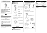
SeeFig.5.Beforeusingtheequipment,openthell
cap(P)andaddGracoPartNo.16W645ISO220
silicone-freesyntheticgearoil.Checktheoillevelin
thesightglass(K).Filluntiltheoillevelisnearthe
halfwaypointofthesightglass.Theoilcapacityis
approximately1.5quarts(1.4liters).Do Do
Do
not not
not
overll. overll.
overll.
NOTE: NOTE:
NOTE:
Two1quart(0.95liter)bottlesofoilare
suppliedwiththeequipment.
Figure5SightglassandOilFillCap
Flush Flush
Flush
Before Before
Before
Using Using
Using
Equipment Equipment
Equipment
Thepumpuidsectionwastestedwithlightweight
oil,whichisleftintheuidpassagestoprotectparts.
Toavoidcontaminatingyouruidwithoil,ushthe
equipmentwithacompatiblesolventbeforeusing
theequipment.
Control Control
Control
Module Module
Module
Accessory Accessory
Accessory
TheControlModuleAccessoryisrequiredwith
AdvancedE-FloDCmotorstoprovidetheinterface
foruserstoenterselectionsandviewinformation
relatedtosetupandoperation.SeetheControl
ModuleAccessoryKitmanualforinstallationand
operationinformation.
12
3A2096D

Operation
Operation Operation
Operation
Startup Startup
Startup
Tooperatethepump,followtheStartupinstructions
fortheBasicorAdvancedmotorintheMotormanual.
TheAdvancedE-FloDCmotorsrequireinstallationof
the24P822ControlModuleAccessoryKittoprovide
theinterfaceforuserstoenterselectionsandview
informationrelatedtosetupandoperation.Seethe
ControlModuleAccessoryKitmanualforinstallation
andoperationinformation.
Runthepumpataslowspeeduntiltheuidlinesare
primedandallairisforcedoutofthesystem.
Shutdown Shutdown
Shutdown
FollowthePressureReliefProcedure,page13.
Pressure Pressure
Pressure
Relief Relief
Relief
Procedure Procedure
Procedure
Thisequipmentstayspressurizeduntilpressureis
manuallyrelieved.Tohelppreventseriousinjury
fromsplashinguidandmovingparts,followthe
PressureReliefProcedurewhenyoustopspraying
andbeforecleaning,checking,orservicingthe
equipment.
1.Disengagethestart/stopcontrol(C).SeeFig.1.
2.Shutoffandlockoutthefusedsafetyswitch(B).
3.Opentheuiddrainvalve(D),havingawaste
containerreadytocatchdrainage.Leaveopen
untilyouarereadytopressurizesystemagain.
3A2096D 13

Maintenance
Maintenance Maintenance
Maintenance
Preventive Preventive
Preventive
Maintenance Maintenance
Maintenance
Schedule Schedule
Schedule
Theoperatingconditionsofyourparticularsystem
determinehowoftenmaintenanceisrequired.
Establishapreventivemaintenancescheduleby
recordingwhenandwhatkindofmaintenanceis
needed,andthendeterminearegularschedulefor
checkingyoursystem.
Change Change
Change
the the
the
Oil Oil
Oil
NOTE: NOTE:
NOTE:
Changetheoilafterabreak-inperiodof
200,000–300,000cycles.Afterthebreak-inperiod,
changetheoilonceayear.
1.SeeFig.6.Placeaminimum2quart(1.9liter)
containerundertheoildrainport.Removethe
oildrainplug(25).Allowalloiltodrainfromthe
motor.
2.Reinstalltheoildrainplug(25).Torqueto25–30
ft-lb(34–40N•m).
3.SeeFig.7.Openthellcap(P)andaddGraco
PartNo.16W645ISO220silicone-freesynthetic
gearoil.Checktheoillevelinthesightglass(K).
Filluntiltheoillevelisnearthehalfwaypointof
thesightglass.Theoilcapacityisapproximately
1.5quarts(1.4liters).Do Do
Do
not not
not
overll. overll.
overll.
4.Reinstallthellcap.
Figure6OilDrainPlug
Check Check
Check
Oil Oil
Oil
Level Level
Level
SeeFig.7.Checktheoillevelinthesightglass(K).
Theoillevelshouldbenearthehalfwaypointofthe
sightglasswhentheunitisnotrunning.Iflow,open
thellcap(P)andaddGracoPartNo.16W645ISO
220silicone-freesyntheticgearoilasrequired.The
oilcapacityisapproximately1.5quarts(1.4liters).
Do Do
Do
not not
not
overll. overll.
overll.
Figure7SightglassandOilFillCap
Bearing Bearing
Bearing
Pre Pre
Pre
- -
-
Load Load
Load
SeeFig.7.Thebearingpre-loads(R)arefactory
setandarenotuseradjustable.Donotadjustthe
bearingpre-loads.
Flushing Flushing
Flushing
•Flushbeforechanginguids,beforeuidcandry
intheequipment,attheendoftheday,before
storing,andbeforerepairingequipment.
•Flushatthelowestpressurepossible.Check
connectorsforleaksandtightenasnecessary.
•Flushwithauidthatiscompatiblewiththeuid
beingdispensedandtheequipmentwettedparts.
14
3A2096D

Troubleshooting
Troubleshooting Troubleshooting
Troubleshooting
NOTE: NOTE:
NOTE:
Checkallpossibleremediesbeforedisassemblingthepump.
NOTE: NOTE:
NOTE:
TheLEDonthemotorwillblinkifanerrorisdetected.SeeError Error
Error
Code Code
Code
Troubleshooting Troubleshooting
Troubleshooting
inthemotor
manualforfurtherinformation.
Problem Problem
Problem
Cause Cause
Cause
Solution Solution
Solution
Inadequatepowersupply.
SeePowerSupplyRequirements,
page8.
Exhausteduidsupply.Rellandreprimepump.
Cloggeduidoutletline,valves,
etc.
Clear.
Pumpoutputlowonbothstrokes.
Wornpistonpacking.
Replace.Seelowermanual.
Heldopenorwornballcheck
valves.
Checkandrepair.Seelower
manual.
Pumpoutputlowononlyone
stroke.
Wornpistonpacking.
Replace.Seelowermanual.
Nooutput.Improperlyinstalledballcheck
valves.
Checkandrepair.Seelower
manual.
Exhausteduidsupply.Rellandreprimepump.
Heldopenorwornballcheck
valves.
Checkandrepair.Seelower
manual.
Pumpoperateserratically.
Wornpistonpacking.
Replace.Seelowermanual.
Inadequatepowersupply.
SeePowerSupplyRequirements,
page8.
Exhausteduidsupply.Rellandreprimepump.
Cloggeduidoutletline,valves,
etc.
Clear.
Pumpwillnotoperate.
Fluiddriedonpistonrod.Disassembleandcleanpump.
Seelowermanual.Infuture,stop
pumpatbottomofstroke.
3A2096D 15

Repair
Repair Repair
Repair
Disassembly Disassembly
Disassembly
1.Stopthepumpatthebottomofitsstroke.
2.Relievethepressure.Seethe
PressureReliefProcedure,page13.
3.Disconnectthehosesfromthelowerandplug
theendstopreventuidcontamination.
4.Removethe2-pieceshield(12)byinsertinga
screwdriverstraightintotheslot,andusingitas
alevertoreleasethetab.Repeatforalltabs.Do Do
Do
not not
not
usethescrewdrivertoprytheshieldsapart.
5.Loosenthecouplingnut(11)andremovethe
collars(10).Removethecouplingnutfromthe
pistonrod(R).Unscrewthelocknuts(8)fromthe
tierods(6).Separatethemotor(3)andlower
(7).SeeFig.7.
6.Torepairthelower,seethelowermanual.
7.Therearenouser-serviceablepartsinthe
motor.ContactyourGracorepresentativefor
assistance.
Reassembly Reassembly
Reassembly
NOTE: NOTE:
NOTE:
Ifthecouplingadapter(9)andtierods
(6)havebeendisassembledfromthemotor,see
ReassembletheCouplingAdapterandTieRodsto
theMotor,page17.
1.SeeFig.8.Assemblethecouplingnut(11)to
thepistonrod(R).
2.Orientthelower(7)tothemotor(3).Positionthe
loweronthetierods(6).Lubricatethethreadsof
thetierods.Screwthetierodlocknuts(8)onto
thetierods.Tightenthelocknutsandtorqueto
50-60ft-lb(68-81N•m).
3.Insertthecollars(10)intothecouplingnut
(11).Tightenthecouplingnutontothecoupling
adapter(9)andtorqueto90–100ft-lb(122–135
N•m).
4.Installtheshields(12)byengagingthebottom
lipswiththegrooveinthewet-cupcap.Snapthe
twoshieldstogether.
5.Flushandtestthepumpbeforereinstalling
itinthesystem.Connecthosesandush
thepump.Whileitispressurized,checkfor
smoothoperationandleaks.Adjustorrepair
asnecessarybeforereinstallinginthesystem.
Reconnectthepumpgroundwirebefore
operating.
16 3A2096D

Repair
Reassemble Reassemble
Reassemble
the the
the
Coupling Coupling
Coupling
Adapter Adapter
Adapter
and and
and
Tie Tie
Tie
Rods Rods
Rods
to to
to
the the
the
Motor Motor
Motor
NOTE: NOTE:
NOTE:
Usethisprocedureonlyifthecoupling
adapter(9)andtierods(6)havebeendisassembled
fromthemotor,toensureproperalignmentofthe
motorshafttothepistonrod(R).
1.SeeFig.7.Screwthetierods(6)intothemotor
(3)andtorqueto50-60ft-lb(68-81N•m).
2.Screwthecouplingadapter(9)intothemotor
shaftandtorqueto90–100ft-lb(122–135N•m).
3.Reassemblethepumptothemotor,asexplained
inReassembly,page16.
Figure8PumpAssembly
Notes Notes
Notes
for for
for
Fig. Fig.
Fig.
8 8
8
Torqueto50–60ft-lb(68–81N•m).
Torqueto90–100ft-lb(122–135N•m).
3A2096D
17


Parts
Ref Ref
Ref
Part Part
Part
Description Description
Description
Qty Qty
Qty
1
SeePumpMatrix,page20
KIT,mountingbracket,pump;includesitems
4and5;seemanual311619
1
2
SeePumpMatrix,page20STAND,oor
1
3
SeePumpMatrix,page20MOTOR;BasicorAdvanced;seemotor
manual;includesitems3aand3b
1
3a▲16M130LABEL,warning1
3b16W645
OIL,gear,synthetic;ISO220silicone-free;
1quart(0.95liter);notshown
2
4
SeePumpMatrix,page20WASHER
4
5
SeePumpMatrix,page20BOLT
4
6
15G924ROD,tie
3
7
SeePumpMatrix,page20
PUMP,displacement;seelowermanual1
8108683NUT,lock,hex3
915H369ADAPTER1
10184128
COLLAR,coupling
2
11184059NUT,coupling1
1224F251
KIT,shield,coupler(includes2pieces)
1
▲ReplacementDangerandWarninglabels,tags,
andcardsareavailableatnocost.
3A2096D 19

Parts
Pump Pump
Pump
Matrix Matrix
Matrix
Pump Pump
Pump
Part Part
Part
No. No.
No.
Pump Pump
Pump
Series Series
Series
Mounting Mounting
Mounting
Bracket Bracket
Bracket
(Ref (Ref
(Ref
1) 1)
1)
Floor Floor
Floor
Stand Stand
Stand
(Ref (Ref
(Ref
2) 2)
2)
Motor Motor
Motor
(Ref (Ref
(Ref
3) 3)
3)
Washer Washer
Washer
(Ref (Ref
(Ref
4) 4)
4)
Bolt Bolt
Bolt
(Ref (Ref
(Ref
5) 5)
5)
Lower Lower
Lower
Pump Pump
Pump
(Ref (Ref
(Ref
7) 7)
7)
EC1110
AEM001124F413
EC1111
A255143256193EM001110013310010124F413
EC1112
A255143EM001110013310010124F413
EC1210
AEM001224F413
EC1211
A255143256193EM001210013310010124F413
EC1212
A255143EM001210013310010124F413
EC2110
AEM001124F424
EC2111
A255143256193EM001110013310010124F424
EC2112
A255143EM001110013310010124F424
EC2210
AEM001224F424
EC2211
A255143256193EM001210013310010124F424
EC2212
A255143EM001210013310010124F424
EC2310
AEM002124F424
EC2311
A255143256193EM002110013310010124F424
EC2312
A255143EM002110013310010124F424
EC2410
AEM002224F424
EC2411
A255143256193EM002210013310010124F424
EC2412
A255143EM002210013310010124F424
EC2320
AEM002124F426
EC2321
A255143256193EM002110013310010124F426
EC2322
A255143EM002110013310010124F426
EC2420
AEM002224F426
EC2421
A255143256193EM002210013310010124F426
EC2422
A255143EM002210013310010124F426
EC2330
AEM002124F427
EC2331
A255143256193EM002110013310010124F427
EC2332
A255143EM002110013310010124F427
EC2430
AEM002224F427
EC2431
A255143256193EM002210013310010124F427
EC2432
A255143EM002210013310010124F427
EC3310
AEM002124F432
EC3311
A255143256193EM002110013310010124F432
EC3312
A255143EM002110013310010124F432
20 3A2096D
/