Page is loading ...

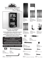
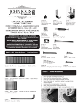
PARTS LIST Lista De Piezas Liste Des Piéces
IMPORTANT: DO NOT RETURN TO STORE!
For missing or damaged parts, technical or assembly questions, please call John Louis Customer
Service at 1-800-480-6985
IMPORTANTE: ¡NO LO DEVUELVA A LA TIENDA!
Llame al servicio al cliente local de John Louis al 1-800-480-6985
para aclarar sus dudas sobre pérdidas, daños, asuntos écnicos y ensamblaje.
IMPORTANT: NE PAS RENVOYER OU RAPPORTER AU MAGASIN!
Si vous avez une question concernant l’assemblage, des piéces manquantes ou endommagées ou
un probléme technique, appelez le Service á la clientéle de John Louis au 1-800-480-6985.
STEP 1 - Assembling Drawer
1. Select drawer side (right or left).
2. Insert cam bolt at hole location.
3. Repeat for 2nd location & other drawer side.
A
Quantity: 1
Drawer face
Frente de cajón
Façade de tiroir
H
Quantity: 2
3/4 in. machine screw
1.9 cm. tornillo de máquina
1,9 cm. vis de la machine
G
Quantity: 1
Drawer handle
Cajón de mango
Poignée de tiroir
I
Quantity: 1
Rubber bumpers
Topes de goma
Butoirs en caoutchouc
B
Quantity: 1
Drawer back
Dorso de cajón
Arrière de tiroir
C
Quantity: 1
Drawer left side
Cajón lateral izquierdo
Côté de tiroir gauche
D
Quantity: 1
Drawer right side
Cajón lateral derecho
Côté de tiroir à droite
E
Quantity: 1
Drawer bottom
Aajuar de cajón
Fond de tiroir
F
Quantity: 2
Drawer glide
Cajón deslizante
Tiroir glisse
K
Quantity: 8
Cam nut
Cam tuerca
Cam écrou
J
Quantity: 8
Cam bolt
Cam perno
Cam boulon
L
Quantity: 8
#6 1/4 in. screw
#6 .635 cm. tornillo
#6 ,635 cm vis
M
Quantity: 8
#6 1 1/4 in. screw
#6 3.17 cm. tornillo
#6 3,17 cm vis
16 IN. DELUXE SOLID WOOD DRAWER
ASSEMBLY INSTRUCTIONS
40.64 CM. INSTRUCCIONES DE MONTAJE CAJÓN DE MADERA SOLIDA
40,64 CM. INSTRUCTIONS DE MONTAGE TIROIR EN BOIS MASSIF
WORKS ONLY WITH THE FOLLOWING:
16 IN. DEEP CLOSET ORGANIZER
16 IN. DEEP TOWER UNIT
When installing multiple drawers, always start from the bottom drawer
location & work upward.
If using doors on top of drawers to create a full tower, you may use
any combination of drawers that equals 36 in. For example: 8,8,8,6,6
- 10,10,10,6 - 10,10,8,8.
FUNCIONA SÓLO CON LO SIGUIENTE:
40.64 CM ORGANIZADOR DEL ARMARIO
40.64 CM UNIDAD DE TORRE DE PROFUNDIDAD
Al instalar varios cajones, comience siempre desde la ubicación cajón
inferior y trabaje hacia arriba.
Si el uso de puertas en la parte superior de los cajones para crear una
torre llena, es posible utilizar cualquier combinación de cajones que
equivale a 36 pulg Por ejemplo: 8,8,8,6,6 - 10,10,10,6 - 10,10, 8,8.
UNIQUEMENT AVEC CE QUI SUIT:
40,64 CM. ORGANISATEUR DE PLACARD
40,64 CM. UNITÉ TOUR EN PROFONDEUR
Lors de l’installation des tiroirs multiples, toujours à partir de
l’emplacement tiroir du bas vers le haut et travailler.
Si vous utilisez des portes au-dessus de tiroirs pour créer une tour com-
plète, vous pouvez utiliser n’importe quelle combinaison de tiroirs, ceci
équivaut à 36 po Par exemple: 8,8,8,6,6 - 10,10,10,6 - 10,10, 8,8.

4. Select drawer face & insert cam bolts at all hole locations.
5. Select drawer back & insert cam nut into hole location with arrow facing
bolt hole.
6. Repeat for all hole locations.
7. Select drawer back & side (right or left).
8. Align the bottom grooves on drawer parts.
9. Insert cam bolts into holes on side of drawer back.
10. Secure by turning cam nuts in clockwise direction until snug.
11. Repeat for remaining drawer side.
12. Insert drawer bottom into sides making sure bottom is within the grooves.
13. Insert cam nuts into sides with the arrow facing the bolt hole.
14. Insert drawer face cam bolts into drawer sides at hole locations.
15. Secure by turning cam nuts in clockwise direction until snug.
16. Attach drawer handle to drawer face using 1 1/2 in. machine screws.
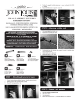
STEP 2 - Attaching Drawer Glides
1. Expand drawer glide to full extension.
2. Move lever & pull out glide to seperate.
3. Position drawer to determine slide placement. Slide position is determined
by which score mark aligns with tower groove.
4. Place slide at the determined score mark. The open end should face the
drawer back.
5. Center the screw holes with the score mark.
6. Secure the slide with 1/2 in. screws at the vertical oval locations.
7. Repeat for the 2nd slide.

8. Place the slide into grooves at desired locations. Slide anges should slot
into the tower grooves. Rubber stopper should be positioned at the back
wall.
9. Secure the slide with 1 1/4 in. screws at back and front location.
10. Repeat for 2nd slide.
STEP 3 - Inserting & Adjusting Drawer
1. Insert drawer into glides.
2. Open & close drawer to lock glides.
3. Loosen front screw to adjust drawer face up & down position.
4. Use 1/2 in. screw at round hole location to secure drawer face position.
5. Repeat steps for remaining drawer stack.
PASO 1: Armado de los cajones
1. Seleccione el lateral del cajón (derecho o izquierdo).
2. Inserte el perno pasador en el oricio.
3. Repita el procedimiento en el segundo oricio y en el otro lateral del cajón.
4. Seleccione el frente del cajón e inserte los pernos pasadores en todos los
oricios.
5. Seleccione la parte posterior del cajón e inserte la contratuerca en el
oricio con la echa en dirección al oricio del perno.
6. Repita el procedimiento para todos los oricios.
7. Seleccione la parte posterior y el lateral (derecho o izquierdo) del cajón.
8. Alinee las ranuras de la parte inferior sobre las partes del cajón.
9. Inserte los pernos pasadores en los oricios del lateral de la parte posterior
del cajón.
10. Fíjelos girando las contratuercas en el sentido de las agujas del reloj hasta
que queden bien ajustados.
11. Repita el procedimiento en el otro lateral del cajón.
/
