Page is loading ...

VB6000 Series
User Manual
C 2005 Thermaltake Technology Co.,Ltd. All Rights Reserved.
www.thermaltake.com

User's Manual
Contents
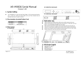
Chapter Product Introduction
1.1 Specification
1
Chapter Case Mechanical Operation
2.1 How to remove/install the side panel 2
2.2 5.25" & 3.5" Device Installation 3
2.3 PCI slot tool-free function operation 4
2.4 Front Fan Filter Removal and Cleaning 5
Chapter Motherboard
&
Leads Installation
3.1 Motherboard Installation 6
3.2 Case LED connections 7
3.3 USB 2.0 & IEEE 1394 firewire connections 8
3.4 Ear & MIC connections 9
VB6000B Series - Swing
TM
4.1 Purepower power supply (optional) 10
Chapter4 Other

User's Manual
1 2
VB6000B Series - Swing
To remove the side panel, please unscrew
from the back of the case.
Pull the side panel to
release it.
1.1 Specification
2.1 How to remove/install the side panel
1
2
3
Push the side panel to fit the both side of
rail of the case.
To re-install the side panel, just push the panel to fix the both side of
the rail, then fix it by screws.
4
VB6000SNSVB6000BNS VB6000SWS
See-through
side panel
§ High efficiency ventilation: 12cm silent fan in rear
§ Tool Free when installing 5.25 & 3.5 device.
§ Dual USB 2.0, IEEE 1394 Firewire, Audio & Speaker ports
§ Stylish streamline form design
§ Thumb-screws for easy opening side panel
§ EMI protection spring
Features
7.65 kgNet Weight
Micro ATX , Standard ATX
VB6000BWS
Front (Intake) : 120 x 120 x25 mm, 1300rpm, 17dBA (optional)
Rear (Exhaust) : 120 x 120 x25 mm, 1300rpm, 17dBA
430 x 190 x 500 mm
Black / Silver
Middle TowerCase Type
7Expansion Slots
Motherboards
color
Chassis: 0.8 mm SECCMaterial
10
4 x 5.25 , 2 x 3.5
4 x 3.5
Drive Bays
-Front Accessible
-Internal
Cooling System
Dimension (H*W*D)
Model VB6000SNSVB6000BNS VB6000SWS
See-through
side panel
§ High efficiency ventilation: 12cm silent fan in rear
§ Tool- Free when installing 5.25" & 3.5" device.
§ Dual USB 2.0, IEEE 1394 Firewire, Audio & Speaker ports
§ Stylish streamline form design
§ Thumb-screws for easy opening side panel
§ EMI protection spring
Features
7.65 kgNet Weight
Micro ATX , Standard ATX
VB6000BWS
Front (Intake) : 120 x 120 x25 mm, 1300rpm, 17dBA (optional)
Rear (Exhaust) : 120 x 120 x25 mm, 1300rpm, 17dBA
430 x 190 x 500 mm
Black / Silver
Middle TowerCase Type
7Expansion Slots
Motherboards
color
Chassis: 0.8 mm SECCMaterial
10
4 x 5.25", 2 x 3.5"
4 x 3.5"
Drive Bays
-Front Accessible
-Internal
Cooling System
Dimension (H*W*D)
Model

User's Manual
VB6000B Series - Swing
3 4
2.2 5.25" & 3.5" Device Installation
5.25" Device Installation:
Attach the included tool-less guide rail on
the side of 5.25" device, then insert it into
the 5.25" bay.
3.5" Device Installation:
Additional HDD drives can be installed into
the HDD cage within the chassis.
Please attach the included tool-less
guide rail on the side of HDD drive, then
insert it into the HDD cage.
1
2
Take up the holder
Pull out the holder
Insert the PCI card into the
PCI slot
Push in the holder
Press down the holder
2.3 PCI slot tool-free function operation
1
2
3
4
5
Pull the front panel to release it.

User's Manual
VB6000B Series - Swing
2.4 Front Fan Filter Removal and Cleaning
5 6
Take off the front bezel, then the filter
can be removed and washed.
1
Each motherboard has different standoff layout. It is highly
suggested that you refer to your motherboard's manual when
installing motherboard into Case. This is applicable with Standard
ATX, Micro ATX motherboards. Your motherboard may require a
special I/O Panel, which should be included with your motherboard.
Case include the standard I/O Panel which is used by majority of
today's motherboard.
Placement Direction:
When Installing the motherboard, make sure you follow the direction
provided by your motherboard manufacturer. On most standard
motherboards, the edge with external ports goes to the rear part of the
chassis. It is highly recommended that you install CPU, heat sink and
modular components before fixing the motherboard inside the chassis.
= the locations of
the screw holes.
Note these locations
and place included
standoffs on the
chassis first.
This side
towards the rear
of the chassis
Above illustration is a sample of what the motherboard's layout. For more detail
screw hole placement, please refer to your motherboard manual.
3.1 Motherboard Installation

User's Manual
VB6000B Series - Swing
7 8
On the front of the case, you can find some
LEDs and switch leads (SPEAKER*1, POWER
SW*1, POWER LED*1, H.D.D. LED*1, RESET
SW*1). Please consult user manual of your
motherboard manufacturer, then connect these
leads to the panel header on the motherboard.
These leads are usually labeled; if not, please
trace them back to the case front to find out
their source.
3.2 Case LED connections
- POWER LED connects to your M/B at the PLED
- POWER SW connects to the PWR connector on
the motherboard.
- SPEAKER connector: find out the 4-pin labeled
SPEAKER on the M/B then connect it.
- H.D.D LED connects to the 2-pin labeled HDD
LED connector.
RESET SW connects to the RSW connector on
the motherboard.
There are four wires with different
connectors inside the case, these are
shown as follow:
USB1(4+1pin),
USB2(4+1pin),
IEEE1394,
front Audio connector
USB2.0 connection: it is compatible
for USB1.1
Please consult your motherboard manual to find
out the position of USB 2.0 connection on your
motherboard. You can see 10-pins in two rows.
- USB1 includes VCC1, USB1-, USB1+,
GND1, GND.
- USB2 includes VCC2, USB2-, USB2+,
GND2, GND.
Connect "2.0 USB1" to the one of two rows on
the motherboard.
Connect "2.0 USB2" to the other row.
3.3 USB 2.0 & IEEE 1394 firewire connections
Note: One or two pins may be shown in both rows as NC on some motherboards,
please ignore it, NC means empty pin
USB 1
IEEE1394
USB 1
(Support USB 2.0))
MIC EAR

User's Manual
VB6000B Series - Swing
IEEE 1394 firewire connection
There are eight wires (two GND, VG, VP, TPA+,
TPA-, TPB+, TPB-)with connectors coming rom
the IEEE 1394 of the case. Please consult your
motherboard manual to find out the position of
IEEE 1394 connection on your motherboard.
You can see 10-pins in two rows.
9 10
3.4 Ear & MIC connections
Please consult your motherboard manual to find
out the section of "front panel audio connector".
1.connect "MIC-VCC" to "MIC POWER"
or "MICPWR" on your motherboard
- Power pin: connect VP connector to it.
- Ground pin: connect VG connector to it ( next to the VP connector)
- Data pin: connect TPB- connector to the TPB- data pin,
connect TPB+ connector to the TPB+ data pin,
connect TPA- connector to the TPA- data pin, connect TPA+
connector to the TPA+ data pin.
- Ground pin: Connect two GND connectors to the other two
GND ground pins
2.connect "MIC-IN" to "MIC INPUT"
or "MIC2" on your motherboard.
3.connect "GND" to "GROUND"
or "AGND" on your motherboard.
4.connect "EAR L" to "AUD_FRONT_L"
and "EAR R" to "AUD_FRONT_R".
5.connect "LINE L" to "AUD_RET_L"
and "LINE R" to "AUD_RET_R".
TM
The Thermaltake Silent Purepower specification meets Intel
Pentium 4 and AMD K7; it offers plenty of functions, which mainly
include:
TM
4.1 Purepower power supply (optional)
4.Over current protection.
3.Over voltage protection / Under voltage protection.
2.Short circuit protection on all output.
oo
1.Over thermal protection at 100 C-105 C
TM
The functions can assure the Silent Purepower meet the balance in
TM
noise control and heat exhausted. The Silent Purepower provides
complete protection function as follow:
2.Ultra Silent:Ball bearing fans with high reliability and super low
acoustic noise under all load condition.
TM
1.Automatic Fan Speed Control: The Silent Purepower power
supply can detect the inside heat and automatically adjust the fan
speed to provide adequate airflow.
Besides, Thermaltake enables the quality assurance of the Silent
TM
Purepower : 100% Hi-POT and ATE Function Test, 100% Burn-In and
AC Input cycled on/off under high temperature condition. Furthermore,
it has been approved by UL, CSA, TUV, VDE, NODIC, CB, FCC, CE,
CNS.
There are three main products of Thermaltake PSU, it is divided into
standard, VR and specialty power supply unit. Please refer to
http://www.thermaltake.com/purepower/main.htm
/