Page is loading ...

ABRASIVE MEDIA
BLAST CABINET – B100
INS TRUCTIONS
Item #21301

2 Eastwood Technical Assistance: 800.343.9353 >> tech@eastwood.com
The EASTWOOD ABRASIVE MEDIA BLAST CABINET – B100 is constructed of heavy gauge steel with a quality powdercoated finish for maximum durability
and trouble-free service. It features a high-intensity dual-tube fluorescent work lamp for increased visibility and a baffled, flow-through ventilation design with an
included integral, high capacity vacuum unit, all in a compact, space saving configuration. The unique clam shell front opening design provides much greater ease
and safety with a low lift-over height when blasting larger or heavier items.
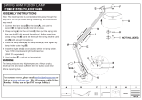
INCLUDES
COMPONENTS
(1) Blast Cabinet Assembly – A
(4) Legs – B
(2) Leg Side Braces – C
(1) Light Fixture (installed under lid for shipping) – D
(2) Fluorescent Tubes – E
(1) Glass Lamp Protection Panel (installed under lid for shipping) – F
(1) Pick-up Tube/Gun/Hose Assembly – G
(1) Perforated Floor Panel – H
(1) Regulator/Air Valve/Foot Pedal Assembly – J
(1) Vacuum/Filter Assembly – K
(5) Peel-Off Window Shields
(5) Peel-Off Lamp Protection Panel Shields
(3) Spare Nozzles
(1) Roll Teflon Tape
HARDWARE
(35) M6 x 12mm Pan Head Screws
(35) M6 Self-Locking Nuts
REQUIRED FOR USE
• The inlet air supply must have a moisture separator capable of removing all moisture and impurities from the air supply. Moisture and/or oil in the
air supply will cause clumping and clogging of the abrasive media.
• The included regulator must be used to limit incoming air pressure to 90 PSI maximum. Excessive air pressure can cause permanent damage to the unit
and possible serious personal injury from bursting.
• For best results, a compressor capable of providing a minimum of 12 CFM @ 90 PSI is required. Less available CFM will not provide sufficient force to
allow the Blaster to adequately remove rust and or paint.
• The use of Eastwood blast media is strongly recommended for proper operation. Use care to avoid using excessive grit size which can block the Nozzle.
SPECIFICATIONS
• Electrical current requirement: Grounded 120 Volt AC, 15 Amp, 60hz
• Air supply requirements: Minimum 12 CFM @ 90 PSI
• Internal Dimensions: 48” wide x 24” deep x 24” high
• Weight Capacity: 220 lbs. [100 kgs]
• Media Capacity: 150 lbs. [68 kgs]
A
B
C
D
E
F
G
H
J
K
Hardware

To order parts and supplies: 800.343.9353 >> eastwood.com 3
READ INSTRUCTIONS
Thoroughly read and understand these product instructions before using the Blast Cabinet.
• Keep these product instructions for future reference.
HEALTH AND INJURY HAZARDS!
• Silica based abrasives have been linked to severe respiratory disease. Avoid breathing dust produced by the Blast Cabinet. Always
wear appropriate NIOSH approved breathing apparatus. DO NOT use any sand or silica-based abrasives with this Blast Cabinet.
• The Blasting Gun will eject particles, dust and sharp fragments at high velocity during operation. Eye protection should be worn at
all times when operating this tool. Use ANSI approved safety glasses. Everyday eyeglasses are NOT safety glasses.
• NEVER operate the Blast Cabinet in an indoor area without the vacuum operating. Always make sure the lid is securely latched
and sealed before operating.
• For maximum safety and results, operate the blast cabinet with a properly maintained vacuum unit. If dust is seeping out of the
vacuum unit, stop immediately! This is a serious health hazard! Follow vacuum filter cleaning and maintenance procedure before
resuming work.
• Always make sure the work area is isolated from any unprotected persons, pets or property.
• The Blast Gun can quickly start up while connected to an air supply causing serious personal injury.
Always disconnect the Blast Cabinet from the air supply before changing nozzles, removing clogs or other maintenance.
• Excessive air pressure can cause tool to explode resulting in tool damage and personal injury. DO NOT exceed 90 psi [6.3 bar] of
tool inlet air pressure.
HEALTH AND INJURY HAZARDS!
• The Eastwood Abrasive Media Blast Cabinet consists of large, heavy metal components which can cause potentially serious injuries if
allowed to drop. Avoid pinching hands while handling parts during assembly. The assistance of a helper during assembly is necessary.
The use of safety shoes is advised.
• Abrasive Blasting can generate excessive noise. Wear appropriate ANSI approved hearing protection while using.
• The high velocity media stream produced by this Abrasive Blaster can abrade and remove exposed flesh causing serious injury.
Never operate the Blast Cabinet with lid open.
• Always dispose of exhausted media properly following all local hazardous material disposal regulations. Levels of hazardous materials
such as lead, zinc chromate, etc. may be present in coatings being removed. Additional protection may be required in the presence of
these substances.
SHOCK HAZARD!
• Under certain conditions (e.g. low atmospheric humidity levels, type of media being used and/or type of material being blasted),
the friction of abrasive blasting may generate static electricity and result in shocking.
DANGER indicates a hazardous situation which, if not avoided, will result in death or serious injury.
WARNING indicates a hazardous situation which, if not avoided, could result in death or serious injury.
CAUTION used with the safety alert symbol, indicates a hazardous situation which, if not avoided, could result in minor or moderate injury.
NOTICE is used to address practices not related to personal injury.
SAFETY INFORMATION
The following explanations are displayed in this manual, on the labeling, and on all other information provided with this product:

4 Eastwood Technical Assistance: 800.343.9353 >> tech@eastwood.com
FIG. 1
ASSEMBLY
PREPARING BLAST CABINET FOR ASSEMBLY
• With a capable helper, carefully set the Blast Cabinet on its
back, on a secure working surface, with the round glove
holes facing upward (FIG 1).
REMOVE LIGHT FIXTURE AND GLASS PANEL FROM SHIPPING
POSITION
(D & F FROM A)
• Carefully unlatch the clasps holding the Clamshell Lid
closed and allow it to slowly open with pressure from the
attached Gas Cylinders (FIG 2).
• Reach in and while supporting the Light Fixture (D), loosen
the six M6 screws holding it in place at the underside of the
roof of the Cabinet.
• Carefully withdraw the Light Fixture (D) and the Glass
Lamp Protection Panel (F).
• Set the Light Fixture (D) and the Glass Lamp Protection
Panel (F) aside in a secure location along with the six
removed screws for top of Cabinet installation later.
The Eastwood Abrasive Media Blast Cabinet
consists of large, heavy metal components
which can cause potentially serious injuries if
allowed to drop. Avoid pinching hands while
handling parts during assembly. The assis-
tance of a helper during assembly is neces-
sary. The use of safety shoes is advised.
FIG. 2
Wear appropriate work gloves to avoid
receiving cuts from sharp edges of the
Glass panel (F).

To order parts and supplies: 800.343.9353 >> eastwood.com 5
FIG. 3
ATTACH LEGS TO BLAST CABINET (B TO A)
• Slide a Leg (B) under the rear, lower corner of the cabinet
(A) as a rear leg with 4 screw holes aligned (FIG 3).
NOTE: 2 of the screw holes are inaccessible at this point.
• Pass 2 M6 x 12mm Screws through holes from the outside,
add M6 Nuts (FIG 4). Tighten securely.
• Place another Leg (B) over the front corner of the Cabinet
(A) aligning 4 sets of holes.
NOTE: It is advisable to have a helper support the Leg while
aligning holes, and installing hardware.
• Insert 4 M6 x 12 mm Screws from the outside and add
4 Nuts (FIG 5).
• Repeat for front and rear legs at opposite side.
FIG. 4
FIG. 5
A
✓
B
✓
Holes
✓
✓
✓
A
✓
B
✓

6 Eastwood Technical Assistance: 800.343.9353 >> tech@eastwood.com
FIG. 6
FIG. 7
FIG. 8
ADD LEG SIDE BRACES TO LEGS (C TO B)
• Place a Leg Side Brace behind a set of Legs and align the
screw holes (FIG 6).
• Add 2 M6 x 12mm Screw and Nuts and tighten securely
(FIG 6).
• Close the Clamshell Lid against Gas Cylinder pressure and
latch Clasps securely.
• With helper, place gloved hands along rubber seal inside
the open light fixture slot at the top of the Cabinet and lift
slowly and steadily to upright position. DO NOT allow legs
to collapse.
• Align all holes in Legs and Cabinet and add an additional
4 sets of Screws and Nuts per side. Tighten all hardware
securely (FIGS 7 & 8).
The following step requires the assistance of
a capable helper as the unit is very heavy!
When raising, the rear Legs are not fully at-
tached to the Cabinet and may be damaged
or bent if not properly supported. The use of
safety shoes is strongly advised.

To order parts and supplies: 800.343.9353 >> eastwood.com 7
ADD FLUORESCENT TUBES (E) TO LIGHT FIXTURE (D)
GLASS PANEL TO TOP OF CABINET LOCATION (D & F TO A)
• Place the Light Fixture on its back and remove the
Florescent Tubes (E) from packaging.
• Align contact pins at the end of Fluorescent Tubes with the
spring-loaded lamp receptacles (FIGS 9 & 10), push in,
and allow pins at opposite end of Tube to fit into opposite
receptacle.
FIG. 9
FIG. 10

FIG . 11
FIG. 12
FIG. 13
INSTALL LIGHT FIXTURE AND GLASS PANEL TO TOP OF
CABINET LOCATION (D & F TO A)
• Set and center the Glass Lamp Protection Panel (F) over
the rubber seal WITH PEEL-OFF PROTECTIVE COVER facing
downward toward inside of Cabinet (FIG 11).
• Place the Light Fixture (D) with Switch facing forward over
the Glass Panel (F) and align the 3 mounting slots per side
with the 6 holes in the cabinet top (FIG 12).
• Add the 6 previously removed Light Fixture Screws.
NOTE: No nuts are required as these are pre-attached
weld-nuts (FIG 13).
Wear appropriate work gloves to avoid
receiving cuts from sharp edges of the
lass panel (F).
8 Eastwood Technical Assistance: 800.343.9353 >> tech@eastwood.com

To order parts and supplies: 800.343.9353 >> eastwood.com 9
MOUNT PICK-UP TUBE/BLAST GUN/HOSE (G)
• Place the end of the Pickup Tube (G) at the bottom right of
the Hopper section of the Cabinet (A), Align the mount-
ing holes of the bracket with the 2 holes in the right front
Hopper panel and secure it with 2 M6 Screws and Nuts
(FIG 14).
• Slip the end of the Orange Air Supply Hose over the inner
nipple of the 90° Bulkhead Fitting and secure it with the
Compression Ring (FIG 15).
FIG. 14
FIG. 15

10 Eastwood Technical Assistance: 800.343.9353 >> tech@eastwood.com
INSTALL THE PERFORATED CABINET FLOOR (H)
• Let the Abrasive Blasting Gun and Hose (G) hang out of the
right front corner of the Cabinet.
• Set the Perforated Cabinet Floor (H) (with angled cut off
corner toward right front of cabinet) and allow the edges to
rest on the internal Cabinet support flanges (FIGS 16 & 17).
FIG. 16
FIG. 17

To order parts and supplies: 800.343.9353 >> eastwood.com 11
MOUNT REGULATOR/AIR VALVE/FOOT PEDAL ASSEMBLY (J)
• Set the Regulator/Air Valve in place on the upper front face
of the Left Leg, align the mounting holes of the bracket
with the 2 holes in the Leg and secure it with 2 M6 Screws
and Nuts (FIG 18).
• Slip the end of the Orange Air Supply Hose over the outer
nipple of the 90° Bulkhead Fitting and secure it with the
Compression Ring (FIG 19).
FIG. 18
FIG. 19

12 Eastwood Technical Assistance: 800.343.9353 >> tech@eastwood.com
FIG. 20
INSTALL VACUUM/FILTER ASSEMBLY TO CABINET (K TO A)
NOTE: The Vacuum/Filter Assembly is moderately heavy, and it is
best to remove the Motor and Filter before installing on the Cabi-
net. Also, the assistance of a capable helper is necessary.
• Place the Vacuum/Filter Assembly on the floor and unlatch
the 2 Clasps.
• Pull the Motor & Filter out of the top of the Housing and set
it aside.
• With the assistance of a helper, align the mounting holes of
the brackets with the 4 holes at the upper back wall of the
Cabinet. Secure it in place using 4 sets of M6 Screws and
Nuts (FIG 20).
• Carefully lower the Motor/Filter Assembly back into the
mounted Housing and latch the Clasps securely (FIG 21).
• Connect the Plug on the power supply cord with the
female Receptacle on the cord attached to the Light
Fixture (FIG 22).
• The Eastwood Abrasive Media Blast Cabinet is now fully
assembled and ready for set-up.
FIG. 21
FIG. 22

To order parts and supplies: 800.343.9353 >> eastwood.com 13
FIG. 23
SET-UP BLAST CABINET FOR USE
• Add Eastwood approved Blast Media. Fill to within 10” of
the Perforated Floor support flanges. DO NOT OVERFILL.
Overfilling will degrade performance. DO NOT USE SAND IN
THIS BLAST CABINET!
NOTE: for best results and to avoid nozzle clogging, do not
use media larger than 60 grit particle size.
• Close the Air Inlet Valve on the Regulator/Air Inlet Assembly
(FIG 23).
• Connect to a clean and dry 90 PSI, 12 CFM minimum
air source.
NOTICE: The inlet air supply MUST have a moisture separa-
tor capable of removing all moisture and impurities
from the air supply. Moisture and/or oil in the air sup-
ply will cause clumping and clogging of the media. The
Eastwood # 34103 Moisture Separator (Not Included)
works well.
OPERATION
• Open the front-loading Lid, place object to be blasted on
the Perforated Floor Panel.
• Open the Air Inlet Valve on the Regulator/Air Inlet Assembly
(FIG 24).
• The included Regulator is used to limit incoming air pres-
sure. The Regulator should be adjusted to 90 PSI maxi-
mum. Excessive air pressure can cause permanent damage
to the unit.
• Connect to a properly grounded, 120V AC, 20 Amp, 60Hz
outlet.
• Close and securely latch the Lid.
• Set Vacuum & Light Switches to “ON”.
• Place hands into Gloves.
• Grip the Blast Gun firmly.
• Depress the Foot Pedal to discharge the blast stream.
• Direct the blast stream at the workpiece at an ideal 60°-
45° angle range.
NOTE: Avoid angles of 90° (causes excess Nozzle wear,
excess wear on inside of cabinet and glass.) or less than
30° (media tends to glance off workpiece).
• When done, release Foot Pedal and allow Vacuum to run
several minutes until all dust is clear from the Cabinet.
• Turn off Vacuum & Light.
• Shut off Air Inlet Valve.
• Open Lid.
• Disconnect Air Supply when not in use.
FIG. 24
Closed
Open

14 Eastwood Technical Assistance: 800.343.9353 >> tech@eastwood.com
MAINTENANCE
REPLACE PEEL-OFF WINDOW SHIELD
• The interior side of tempered glass Lid Window is equipped with a replaceable, full-view, peel-off, self-adhesive flexible window shield.
It will become cloudy with use.
To replace:
- Peel off worn protector.
- Gently clean glass with a soft cloth and glass cleaner or alcohol.
- Peel off adhesive protective strips and apply replacement shield to interior glass surface. Press on adhesive areas to ensure an abrasive proof seal.
REPLACE PEEL-OFF LAMP PROTECTION PANEL SHIELD
• The interior side of tempered glass Lamp Protection Panel is equipped with a replaceable, peel-off, self-adhesive flexible window shield.
It will gradually become cloudy with use and can diminish light intensity.
To replace:
- Peel off worn protector.
- Gently clean glass with a soft cloth and glass cleaner or alcohol.
- Peel off adhesive protective strips and apply replacement shield to interior glass surface. Press on adhesive areas to ensure an abrasive proof seal.
CERAMIC NOZZLE REPLACEMENT
• Replace the Nozzle when you notice excessive air and blast
media being used or cleaning efficiency is reduced. Nozzle
replacement on the Blast Gun is easy. After disconnecting
the unit from the air supply, unthread the Nozzle Fer-
rule from the front of the Gun Body, remove the Ceramic
Nozzle, install replacement and thread the Nozzle Ferrule
back in place (FIG 25).
• The Blast gun is now once again ready for use.
JET REPLACEMENT
• Replace the Jet when you notice excessive air and blast
media being used or cleaning efficiency is reduced.
To replace:
- Disconnect Blast Cabinet from air supply.
- Remove Air Inlet Fitting from the rear of the
Jet Assembly.
- Loosen Air Jet Lock Nut and turn Air Jet out of rear of Gun.
- Install new Air Jet, then tighten Air Jet Lock Nut.
- Reinstall Air Inlet Fittings.
- The Blast gun is now once again ready for use.
FIG. 25
Ferrule
✓
✓
✓
✓
Nozzle Jet Air
Inlet
Fitting
Lock Nut
✓

To order parts and supplies: 800.343.9353 >> eastwood.com 15
REPLACE BLAST MEDIA
• To drain blast media from Blast Cabinet:
- Disconnect air supply to Blast Cabinet.
- Place a box or container suitable for holding the blast
media under the Drain Panel of the Hopper.
- Carefully release the Clasp of the Drain Panel Latch
(FIG 26).
- Allow the media to drain. Gently thumping the sides of
the Hopper may be helpful in maintaining media flow.
- When draining stops, clear excess media from
seal area of the Drain Panel, close and latch the
Clasp securely.
- Add Eastwood approved Blast Media. Fill to within
10” of the Perforated Floor support flanges.
DO NOT OVERFILL. Overfilling will degrade
performance.
DO NOT USE SAND IN THIS BLAST CABINET!
NOTE: for best results and to avoid nozzle clogging,
do not use media larger than 60 grit particle size.
FIG. 26
The fine dust accumulated by this unit is a Health Hazard! Avoid breathing dust produced by handling the Filter. Always wear ap-
propriate NIOSH approved breathing apparatus when cleaning, emptying or maintaining the unit and use in a well-ventilated area.
Always dispose of exhausted media properly following all local hazardous material disposal regulations. Levels of hazardous
materials such as lead, zinc chromate, etc. may be present in coatings being removed. Additional precautions may be required
in the presence of these substances.

16 Eastwood Technical Assistance: 800.343.9353 >> tech@eastwood.com
VACUUM MAINTENANCE
The Vacuum is designed to keep the dust level in the cabinet low for maxi-
mum visibility while blasting. As the Blaster is operated, make-up air enters
the vent at the left front Hopper panel, circulates through the cabinet and is
drawn though the outlet baffle at the upper rear panel.
• After every 10 minutes of blasting, operate the Filter Plunger at the
side of the Vacuum Housing (FIG 27).
To do so: Strike the plunger sharply with the side or palm of the
hand. This will strike the Filter allowing any caked accumulation of
media dust to fall into the bottom hopper. As the Filter is repeatedly
struck, the hopper will fill with media dust and must be emptied. To
do so: unlatch the Clasp on the conical vacuum hopper base and
allow the dust to discharge into a container.
• If it becomes apparent that the vacuum is failing to clear the dust from the cabinet while dusting, the Filter must be cleaned. To do so:
- Turn off unit and unplug the power supply cord.
- Unlatch the Clasps on the sides of the Vacuum/Filter Assembly and pull the Motor & Filter out of the top of the Housing and set it upside down
with the Filter base upward.
- Loosen and remove the Filter Retaining Wingnut and Washer (FIG 28).
- Pull the Filter free of the Motor Unit.
- Clean dust from the rubber seal.
- Using a suitable blow gun and compressed air source, blow air through the Filter from the inside out.
- When done, replace Filter and secure it with the Filter Retaining Washer and Wingnut.
- Replace the Motor & Filter assembly back into the Housing and latch the Clasps securely.
- Reconnect the Power Supply Cord.
The fine dust accumulated by this unit is a Health Hazard! Avoid breathing dust produced by handling the Filter. Always wear ap-
propriate NIOSH approved breathing apparatus when cleaning, emptying or maintaining the unit and use in a well-ventilated area.
Always dispose of exhausted media properly following all local hazardous material disposal regulations. Levels of hazardous ma-
terials such as lead, zinc chromate, etc. may be present in coatings being removed. Additional precautions may be required in the
presence of these substances.
FIG. 27
FIG. 28

To order parts and supplies: 800.343.9353 >> eastwood.com 17
A
B
B
B
B
C
D
E
F
Assembled
“G”
H
J
K
Assembled –
Included with “A”
Assembled –
Included with “A”
J

18 Eastwood Technical Assistance: 800.343.9353 >> tech@eastwood.com
NOTES

To order parts and supplies: 800.343.9353 >> eastwood.com 19
PROBLEM CAUSE CORRECTION
Weak Blast
Stream
Compressor Inadequate Causing
Insufficient Volume of Air (CFM)
to Operate Tool
Verify sufficient air supply to tool. Minimum requirement = 12 CFM @ 90 PSI.
Air Supply Line from Compressor
Too Small
Use air supply line of 3/8” or greater.
Air Supply Line from Compressor
Too Long
Limit air supply line to 25’ or less.
Pinched or Damaged Media Suction Line Replace suction hose. Automotive fuel or heater hose works well.
Moisture or Other Contamination in
Air Supply
Check for and eliminate source of moisture in air line and blast gun.
Media Surging
Moisture in Media and or/Air Supply
Install a moisture separator capable of removing all moisture and impurities
from the air supply.
Debris or Blasting Residue in Gun Nozzle
Clean out gun nozzle then drain and sift blast media to remove debris
before re-use.
Excessive Media in Hopper
For best results, operate blaster with the Pick-up Tube inlet buried several
inches in media. 50 lbs. of media is generally sufficient.
Media Stream
Suddenly
Stops
Dirt or Debris in Media Suction Line
to Gun
To dislodge blockage, with lid closed, place a blast gloved finger over the
nozzle outlet and momentarily depress Foot Pedal.
Contaminated Media Drain and sift blast media to remove debris before re-use.
View in
Cabinet
Becomes
Obstructed
Dust is Clogging Filter
Operate Filter Plunger to shake dust form Filter.
Clean Filter per procedure in Maintenance Section.
Filter Housing is Full of Dust
Empty Filter Housing per procedure in Maintenance Section.
Clean Filter per procedure in Maintenance Section.
Plastic Peel-Off Shield is Worn Clean inside of window and replace Peel-off shield.
TROUBLESHOOTING

ADDITIONAL ITEMS
#22022 Blast Media Sifter Screen
#34103 Moisture Separator
#21305 Replacement Air Jet
#20071 Peel-off Lid Window Shields
#21309 Peel-off Light Fixture Shields
#20070 Replacement Gloves
#20073 Lid Window Glass
#21326 Light Fixture Glass
#30999 Dust Filter
#22019 Silicon Carbide Media, 60 Grit
#22021 Aluminum Oxide Media, 60 Grit
#13792 Aluminum Oxide Media, 90 Grit
#22018 Walnut Shell Media, 12/20 Grit
#13779 Ground Glass Media, 40/70 Grit
#13772 Glass Bead Media, 100/170 Grit
#22023 Glass Bead Media, 70/100 Grit
#11806 Soda Media, 10 lbs.
#21135 Replacement Nozzles, 2pc
© Copyright 2019 Easthill Group, Inc. 2/19 Instruction item #21301Q Rev 1
If you have any questions about the use of this product, please contact
The Eastwood Technical Assistance Service Department: 800.343.9353 >> email: tech@eastwood.com
PDF version of this manual is available at eastwood.com
The Eastwood Company 263 Shoemaker Road, Pottstown, PA 19464, USA 800.343.9353 eastwood.com
/