Page is loading ...

User’s Guide
Gilson CPC Systems

Trademarks
All product and company names are trademarks™ or registered® trademarks of their
respective holders. Use of the trademark(s) in this document does not imply any
aliation with or endorsements by the trademark holder(s).

GILSON CPC SYSTEMS | USER’S GUIDE
TABLE OF CONTENTS
1 | SAFETY
2 | Symbols and Notices
3 | Chemical Hazards
4 | Electrical Hazards
4 | Flammable Solvents
4 | Lifting
4 | Replacement Parts
4 | Signs of Damage
4 | Site Requirements
4 | Spacing
4 | Storage and Movement
5 | INTRODUCTION
6 | Description
8 | Unpacking
10 | Technical Specifications
14 | Customer Service
15 | INSTALLATION
16 | Drain Pan and Drain Tube Installation
17 | Plumbing Connections
20 | Electrical Connections
21 | OPERATION
22 | Front Panel
25 | Start Up
26 | Control the System
29 | Loop Injection with Manual Valve
30 | Change the Elution Mode (ASC/DSC)
31 | Power Down
33 | MAINTENANCE
34 | Helpful Hints
34 | Cleaning and Decontamination
36 | Maintenance Schedule
37 | Replace a Seal in a Column Rotary Seal
43 | TROUBLESHOOTING
44 | Troubleshooting Table
46 | Error Messages
47 | Repair and Return Policies
49 | WARRANTY
49 | General
50 | Limited Warranty
51 | REPLACEMENT PARTS
AND ACCESSORIES
55 | MATERIALS
55 | Liquid Contact Materials


1GILSON CPC SYSTEMS | USER’S GUIDE
Chapter 1 | SaFetY
Read this chapter before installing and operating the instrument.
Only trained technical personnel in a laboratory environment may use the instrument for
non-medical, liquid handling purposes. For safe and correct use of the instrument, operating
and service personnel must follow all instructions contained in this guide when installing,
cleaning, and maintaining the instrument. All safety precautions must be observed during all
phases of operation, service, and repair of the instrument.
Failure to comply with these precautions or with warnings described in the user’s guide
violates safety standards of design, manufacture, and intended use of the instrument. Gilson
assumes no liability for customers failing to comply with these requirements.
Read all documentation and safety information for accessories, peripherals, and other
instruments that may be used with this instrument before operating the system.
Refer to the side panel label on the instrument or the Declaration of Conformity document for
the current standards to which the instrument has been found compliant.
IN thIS Chapter
● Symbols and Notices | 2
● Chemical Hazards | 3
● Electrical Hazards | 4
● Flammable Solvents | 4
● Lifting | 4
● Replacement Parts | 4
● Signs of Damage | 4
● Site Requirements | 4
● Spacing | 4
● Storage and Movement | 4

2
SAFETY | GILSON CPC SYSTEMS
SAFETY
Symbols and Notices
The following symbols and notices may appear on the instrument or in this document.
Electrical and Hazard Symbols
SYMBOL
EXPLANATION
Direct Current
Alternating Current
Protective Conductor Terminal
|
Electrical Power ON
O
Electrical power OFF
Caution
Caution, Risk of Electric Shock
Caution, Ultraviolet Light, Risk of UV Radiation
Caution, Two Person Lift Required
Warning, Corrosive Chemical
Caution, Hot Surface

3GILSON CPC SYSTEMS | USER’S GUIDE
SAFETY
Label Symbols
The following label symbols may appear on the instrument:
SYMBOL
EXPLANATION
Reference of the product
Serial Number
Year of Manufacture
Refer to the User’s Guide
Safety Notices
WARNING
Indicates a potentially hazardous situation which, if not avoided, may result in personal injury.
CAUTION
Indicates a potentially hazardous situation which, if not avoided, may result in minor or
moderate injury.
NOTICE
Indicates a potentially hazardous situation which, if not avoided, may result in equipment
damage.
Chemical Hazards
Any chemicals used for analysis should be handled according to good laboratory
practice (GLP). They should also be stored, used, and disposed of in accordance with the
manufacturer’s specifications, as well as local and national regulations. Potentially hazardous
chemicals can be used with the instrument. Use care when handling chemicals and wear
appropriate personal protective equipment (PPE), such as safety glasses, gloves, etc.
The responsible individual must ensure that personnel are not exposed to hazardous
levels of toxic substances as outlined in the Material Safety Data Sheets (MSDSs), or any
documentation provided by local governing bodies such as The Health Protection Agency
(United Kingdom) or The Occupational Safety and Health Administration (United States).

4
SAFETY | GILSON CPC SYSTEMS
SAFETY
Electrical Hazards
Unless specifically instructed, do not remove any protective covers. Detach all sources of
voltage from the instrument before the service, repair, or exchange of parts.
Use only the grounded AC cord provided. Ungrounded power cords can result in electrical
shock and serious personal injury. Faulty or frayed power cords must be immediately
replaced with one of the same type and rating. When it is necessary to use a non-original
power cord, make sure the replacement cord adheres to following specifications and
local building safety codes: 1) European Union Model; Connector A: Male, Type E or F
(Schuko), 16A; Connector B: Female, IEC320/C13, 10A; 250 V~, H05VV-F 3G1.0mm² and
2)UnitedStates and Canadian Model; Connector A: Male Type, NEMA 15-5, 15A; Connector B:
Female, IEC320/C13, 10A; 125 V~, SVT 3x18 AWG.
NOTICE
Use only approved fuses with the specified current rating. The instrument must be operated
within the voltage specified on the right panel of the instrument.
Flammable Solvents
Secure all flammable solvents. The temperature of liquids inside the system must be
25°C(77°F) below the lowest flame temperature of any solvents used.
Lifting
The instrument exceeds the weight one person can lift safely. Two or more people are
required to lift the instrument safely. Always lift the instrument from the base and follow any
unpacking instructions provided with the instrument.
Replacement Parts
Be sure to use only replacement parts mentioned in this user’s guide.
Signs of Damage
Do not attempt to use the instrument if there are visible signs of damage.
Site Requirements
Do not operate the instrument if site conditions are not within specifications.
Spacing
Allow sufficient spacing around the system for proper cooling and for the connection of
power cords, plumbing, injection pump, liquid handler, external detectors, or any other
peripherals.
Storage and Movement
Run a clean solvent through the fluid path before storing the instrument. Do not leave buffer
in the system, as it may cause blockages and damage the seals. Rinse the fluid path and
prevent the liquids from flowing out by inlets and outlets before moving the instrument. Store
the instrument indoors (temperature > 5°C) on a flat surface and in an area with low moisture
and low risk of impact or movement.


6
INTRODUCTION | GILSON CPC SYSTEMS
DESCRIPTION
Description
The Gilson CPC Systems are designed for centrifugal partition chromatography (CPC),
also known as counter‑current chromatography (CCC), a silica‑free,
liquid‑liquid chromatographic (LLC) technique for preparative and industrial‑scale
purifications. Two non‑miscible liquid phases are used: one as the mobile phase eluent and
the other as the stationary phase maintained in the chromatography column by a centrifugal
force. The centrifugal force is created by the rotation of the column, also called the “rotor,”
which is composed of horizontally‑stacked discs.
Gilson CPC Systems can be equipped with several models of columns, which vary in volume
from 100mLto1L.
When used as a standalone unit, an optional kit with manual valves mounted on the right side
of the instrument allows Gilson CPC Systems to change elution mode—ascending(ASC) to
descending(DSC)—and inject sample—load to injection. For more information, refer to Loop
Injection with Manual Valve on page 29 and Change the Elution Mode (ASC/DSC) on page 30.
Injection ranges, typical flow rates, maximumpressures, and rotation speeds vary according
to the column model. Refer to Technical Specifications on page 10.
Gilson CPC Systems are standalone and can be controlled with the built‑in touchscreen and
buttons.
The combination of a Gilson CPC System and PLC Purification System, fully controllable
with Gilson Glider CPC (GGC) Software, creates a complete purification system for various
applications. In this configuration, a detector measures the absorbance and sends the
chromatogram to the onboard control software, after which fractions are collected via the
integrated fraction collector. For more information about PLC Purification Systems, refer to
the PLC2050/2250/2500 Purification System User’sGuide.
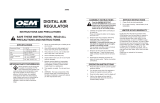
Figure 1
Gilson CPC System with PLC Purification System

7GILSON CPC SYSTEMS | USER’S GUIDE
DESCRIPTION
Rotor Module
WARNING
The user must not access this part of the system due to dangers caused by rotative parts and
hot surfaces.
The rotor module includes the rotor and the fluidic parts as well as the mechanical parts and
the motor that drive the rotor. The brushless servomotor drives the rotor through a system
of pulleys and belt. A tensioner bearing ensures the suitable tension of the belt. The belt has
an antistatic coating. The rotor module is fixed on four absorbers allowing an antivibration
isolation.
The liquid‑liquid interface between the rotating parts and the non‑rotating parts is made with
two rotary seals assemblies, one on each side of the rotor module. They are composed of a
hollow ceramic axis rotating in polymeric double lips seals. The inlet and outlet tubing are
connected to the rotary seal heads. The rotary seals assemblies incorporate a secondary fluid
path called cleaning discs that is used to collect the outflow of possible leakages of the rotary
seals.
Rotor Housing
WARNING
The user must not access this part of the system due to dangers caused by rotative parts and
hot surfaces.
The rotor housing integrates the rotor module and its fluidic connections. A drain pan at the
bottom collects leakages, if necessary. A cover screwed to other panels avoids the access to
the rotative parts.
Electrical Cabinet
WARNING
The user must not access this part of the system due to dangers caused by rotative parts and
hot surfaces.
The electrical cabinet located at the back of the unit integrates all the electronic and
electrical components such as the transformer, power supply, programmable logic controller,
motor servo‑drive, and fan.
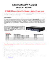
Touchscreen
Fixed on the front panel, the touchscreen allows to
visualize in real time the working parameters of the
instrument, rotor speed and acceleration.
Figure 2
Touchscreen

8
INTRODUCTION | GILSON CPC SYSTEMS
UNPACKING
Unpacking
Upon receipt of the instrument, inspect the exterior of the shipping box. It should arrive
unopened and undamaged. If examination reveals that damage has occurred in shipment,
notify the carrier and Gilson immediately. Refer to Customer Service on page 14.
WARNING
Do not plug in the instrument if any damage is detected. Powering the instrument in a
damaged state may result in serious injury and may damage internal components of the
instrument.
The Gilson CPC Systems are delivered with most major components already assembled. Keep
the original container and packing assembly so the unit may be shipped safely, if necessary.
Carefully unpack the Gilson CPC System and its accessories. Verify that all parts are included
and undamaged. Do this now, even if the Gilson CPC System will not be used immediately.
Many carriers must receive concealed damage claims within seven days of delivery.
CAUTION
The CPC 100, CPC 250, and CPC 250 PRO can each weigh up to approximately
70kg(154lbs.) and an additional 10kg(22lbs.) with packaging. These systems are too heavy
to be lifted or moved by one person safely. To avoid personal injury and for general safety, if
moving or lifting the Gilson CPC System, always get another person to assist you.
The CPC 1000 and CPC 1000 PRO can weigh up to approximately 120kg(264lbs.) and an
additional 10kg(22 lbs.) with packaging. These systems are too heavy to be lifted or moved
by one or two persons safely. To avoid personal injury and for general safety, if moving or
lifting the Gilson CPC System, always get two additional persons (four in all) to assist you.
Do not attempt to lift the instrument from a valve. Always grip it from its base.
Gilson CPC Systems are shipped with rotor and fluid path filled with methanol and water.
Observe all laboratory safety precautions when handling solvents.
To unpack the instrument:
1. Open the box.
2. Remove the accessories packed inside the box.
3. Remove the packing material on top. The unit is not attached to the box, it is put on a
dedicated foam.
4. Lift the unit out of the box and place it at suitable location, such as a lab bench or cart, and
always on a plane surface.
NOTICE
It is recommended to operate the Gilson CPC Systems inside a fume hood to ensure
proper ventilation.
Allow sucient spacing around the system for proper cooling and for making
connections.
Allow at least 20 cm free space around the instrument at all times to allow for proper
tubing and cable connections and to provide adequate ventilation during operation.
Do not place item(s) on the Gilson CPC System.

9GILSON CPC SYSTEMS | USER’S GUIDE
UNPACKING
Unpacking List
The following items are considered standard equipment and are provided with the Gilson
CPC Systems.
STANDARD EQUIPMENT
After the Gilson CPC System and the accessories have been unpacked, you should have the
following:
CPC 100, CPC 250, CPC 250 PRO, and CPC 1000
● Tubing and fittings for column inlet and outlet
○ PEEK Tubing, 1/16" (OD), 0.75 mm (ID), 3 m
○ PEEK Fingertight Fittings for 1/16" tubing (qty. 4)
CPC 1000 PRO
● Tubing and fittings for column inlet and outlet
○ PEEK Tubing, 1/8" (OD), 2.0 mm (ID), 3 m
○ SS Fittings for 1/8" tubing (qty. 4)
All Gilson CPC Systems
● RS‑232 cable
● Power cord, based on destination country
● Waste tubing
● Drain pan
DOCUMENTATION
● Gilson CPC Systems User’s Guide
OPTIONAL ACCESSORIES
● Valves kit, manual (factory installed)
○ 6‑way, 2‑position injection manual valve
○ 6‑way, 2‑position ASC/DSC manual valve
○ Bracket, union, tubing and fittings
○ Injection valve accessory kit, which includes:
○ Large‑bore syringe needle
○ Needle port cleaner
○ 9/64" and 5/64" Allen keys (qty. 2)
○ 1/4"–5/16" wrench
○ Operating instructions
● ASC/DSC valve, manual (factory‑installed)
○ 6‑way, 2‑position ASC/DSC manual valve
○ Bracket, union, tubing and fittings

10
INTRODUCTION | GILSON CPC SYSTEMS
TECHNICAL SPECIFICATIONS
Technical Specifications
Please be aware of the following before operating the Gilson CPC System.
NOTICE
Changes or modifications to the Gilson CPC System not expressly approved by Gilson could
void the warranty.
Gilson CPC Systems
SPECIFICATION DESCRIPTION
Airborne Noise Emission
System Emission
CPC 100
CPC 250
CPC 250 PRO
LAS = 72 dB ±1.5 dB
CPC 1000
CPC 1000 PRO
LAS = 78 dB ±1.5 dB
A frequency weighting, Slow time constant
1 m distance between system (front) and sound level meter
System on a 0.8 m high bench, measuring device at 1.6 m height
Communication Standalone or RS-232
Compliance
Directive/Standard Description
European Directive
2006/42/EC
Directive of the European parliament and of the council of
17 May 2006 on machinery, and amending Directive 95/16/EC
European Directive
2014/30/EU
Directive 2014/30/EU of the European Parliament and of the
Council of 26 February 2014 on the harmonization of the laws of
the Member States relating to electromagnetic compatibility
European Directive
2014/35/EU
Directive of the European Parliament and of the Council of
26 February 2014 on the harmonization of the laws of the
Member States relating to the making available on the market of
electrical equipment designed for use within certain voltage limits
European Directive
2011/65/EU
Directive 2011/65/EU of the European Parliament and of the
Council of 8 June 2011 on the restriction of the use of certain
hazardous substances in electrical and electronic equipment
Control
Onboard via touchscreen interface (4", resolution 320 x 240 pix) and buttons.
PC via RS-232 and GGC Software
Dimensions
(W x D x H)*
*without manual valves
57 x 52 x 46 cm (22.4 x 20.5 x 18.1 in.)
Electrical Protection
System General Fuse
110–120 V~ 6.25A, 250 V~, 6.3 x 32 mm, T-type
220–240 V~ 3A, 250 V~, 6.3 x 32 mm, T-type
TECHNICAL SPECIFICATIONS CONTINUED ON PAGE 11

11GILSON CPC SYSTEMS | USER’S GUIDE
TECHNICAL SPECIFICATIONS
Gilson CPC Systems
SPECIFICATION DESCRIPTION
Environmental Conditions
Specification Definition
Environment Indoor use only
Altitude Up to 2000 m
Temperature range 5°C to 40°C (41°F to 104°F)
Humidity Maximum relative humidity 80% for temperatures up to 31°C,
decreasing linearly to 50% relative humidity at 40°C
External ports Serial port, RS-232
Flow Rate
System Flow Rate (Elution, Typical)
CPC 100 Up to 15 mL/min
CPC 250 Up to 15 mL/min
CPC 250 PRO Up to 80 mL/min
CPC 1000 Up to 50 mL/min
CPC 1000 PRO Up to 350 mL/min
Injection Range
System Range
CPC 100 Up to 1 g
CPC 250 Up to 6 g
CPC 250 PRO Up to 30 g
CPC 1000 Up to 30 g
CPC 1000 PRO Up to 100 g
TECHNICAL SPECIFICATIONS CONTINUED ON PAGE 12

12
INTRODUCTION | GILSON CPC SYSTEMS
TECHNICAL SPECIFICATIONS
Gilson CPC Systems
SPECIFICATION DESCRIPTION
Liquid Contact Materials*
Description Material
Column discs and parts 316L SS
Column discs gaskets
Novaflon® 100*
*Modified PTFE with hollow glass micro-spheres
Manual valves
316 SS
PEEK
Vespel®
Rotation axis
PTFE
Zirconium Oxide
Rotation axis seals
GFP
Hastelloy C
Tubing, fittings, sampleloops, and unions
316 SS
PEEK / ETFE / PTFE
*Refer to MATERIALS on page 55 for more information.
Maximum Pressure
System Pressure
CPC 100, CPC 250, CPC 250 PRO 100 bar (1450 psi)
CPC 1000, CPC 1000 PRO 80 bar (1160 psi)
Power Requirements
Specification Description
Line voltage 110-120 V~ or 220-240 V~
Line frequency 50/60 Hz
Wattage 400 W maximum
Distribution TT or TN power system only
Transient overvoltages Category II
Class 1 equipment
TECHNICAL SPECIFICATIONS CONTINUED ON PAGE 13

13GILSON CPC SYSTEMS | USER’S GUIDE
TECHNICAL SPECIFICATIONS
Gilson CPC Systems
SPECIFICATION DESCRIPTION
Speed and Acceleration
System
Loading Speed
(Setpoint)
Elution Speed
(Setpoint)
Speed Range
Loading
Acceleration
Elution
Acceleration
Acceleration
Range
CPC 100 500 rpm
20 g
1600 rpm
207 g
100 to 3000 rpm
1 to 728 g
CPC 250 500 rpm
19 g
1600 rpm
195 g
100 to 3000 rpm
1 to 685 g
CPC 1000 500 rpm
28 g
1200 rpm
163 g
100 to 1500 rpm
1 to 254 g
CPC 250 PRO 500 rpm
20 g
1600 rpm
207 g
100 to 3000 rpm
1 to 729 g
CPC 1000 PRO 500 rpm
28 g
1200 rpm
163 g
100 to 2000 rpm
1 to 452 g
Weight
System Weight
CPC 100 60 kg (132 lbs.)
CPC 250 70 kg (154 lbs.)
CPC 250 PRO 65 kg (143 lbs.)
CPC 1000 120 kg (264 lbs.)
CPC 1000 PRO 115 kg (253 lbs.)

14
INTRODUCTION | GILSON CPC SYSTEMS
CUSTOMER SERVICE
Customer Service
Gilson, Inc. and its worldwide network of representatives provide customers with the
following types of assistance: sales, technical support, applications, and instrument repair.
If you need assistance, please contact your local Gilson representative. Specific contact
information can be found at www.gilson.com. To help us serve you quickly and efficiently,
please refer to Repair and Return Policies on page 47.


16
INSTALLATION | GILSON CPC SYSTEMS
DraIN paN aND DraIN tube INStaLLatION
Drain Pan and Drain Tube Installation
Slide the drain pan by the front into the two guides placed under the system. Four magnets
fixed on the bottom panel of the unit and four magnets fixed on the drain pan allow it to stay
in place. It is designed to collect leakages.
Figure 4
Drain Pan
The drain tube connects the drain pan at the bottom of the rotor housing to a waste reservoir.
Use a suitable length of polymeric tubing (not supplied). Tube fitting external diameter is 1/4".
Connect the tubing to the adapter in front of the drain pan by inserting the tube end onto
the SS barbed adapter with a gentle twist motion. Push the tubing as far as required. Put the
other end into suitable translucent waste tank to visually control the possible leakages.
/