Page is loading ...

© MuxLab Inc. 94-000692-A
8495 Dalton Rd, Montreal, Quebec, Canada. H4T 1V5
Tel: (514) 905-0588 Fax: (514) 905-0589
Toll Free (North America): (877) 689-5228
E-mail: videoease
@
muxlab.co
m
URL: www.muxlab.co
m
Specifications
Environment
CCTV IP
Devices
CCTV IP cameras, NVR, IP encoder, network switch and any device
with a 10/100Mb/s Ethernet port, supporting IP.
Standard supported
Ethernet side:
IEEE 802.3 10BaseT,
IEEE 802.3U 100Base-TX,
IP ver 4 and 6.
Line side: VDSL-DMT:
ITU-T G993.1 VDSL, ITU-T G997.1,
G.993.2 VDSL2 (profile not selectable).
Maximum distance vs.
speed between unit
(higher speed on camera
side)
Asymmetric speed, using twisted pair* and coax*:
1000ft (330m): 44/31Mbps, 44/31Mbps
2000ft (660m): 34/21 Mbps, 44/28 Mbps
3000ft(1000m): 28/10 Mbps, 39/26 Mbps
4000ft(1350m): 22/5.3 Mbps, 39/21 Mbps
5000ft(1600m): 17/1.2 Mbps, 31/14 Mbps
* The actual data rate will vary on the quality of the copper wire and
environment factors.
Cable between unit
Coax 75 ohm/RG59 or twisted-pair telephone wire AWG24 or better.
Cable for Ethernet port
(Not included)
Two CAT 5/5e/6 UTP cables are required (straight or crossover), up to
330ft(100m).
Indicators
(on both unit)
Power on.
Link/nego between the two unit working.
Ethernet: 10/100 Mb indicator.
Ethernet: Activity.
Ethernet Connectors
(on both unit)
One isolated BNC 75 ohm female to connect remote unit.
One isolated RJ45 to connect remote unit.
One or two RJ45S with LED’s for Ethernet with auto reversal.
One power connector, 2mm.
Pin Configuration to
connect the two unit
(polarity insensitive)
Using RJ45 plug: Pin 4 & Pin 5 (1 pair required only, blue and
white/blue)
Using RJ11/RJ12 plug: Pin 3 & Pin 4 (1 pair required only, blue and
white/blue)
Using BNC: 75 ohms coax cable: Center & Shield (shield is isolated
from chassis)
Power Supply
(Included)
Two 100-240V/5VDC 1.2A power supplies with interchangeable
blades for NA, Europe and UK.
Power Consumption
3.25 Watts each unit
Temperature
Operating: 0° to 60°C Storage: -55° to 85°C
Humidity: Up to 95% non-condensing
Enclosure
Plastic
Dimensions
4.50” x 3.00” x 1.25” (11.4 x 7.6 x 3.2 cm)
Weight
Approx. 1 lb. (0.5 kg)
Compliance
Regulatory: FCC, CE, RoHS Flammability: 94V0
Warranty
2 years
Ordering Information
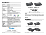
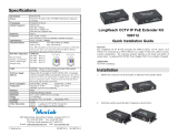
500110 CCTV IP Extender Kit.
CCTV-IP Extender Kit
500110
Quick Installation Guide
Overview
The CCTV-IP Extender Kit (500110) allows IP camera equipment (or any other IP
equipment) to be connected up to 1 mile (1600 m) using one coax cable with BNC or
one Cat 5/5e/6 unshielded twisted pair cable in a point-to-point configuration. The
maximum distance is dependent on speed required, type and length of cable. The kit
comes with one transmitter (camera side), one receiver (network side) and two identical
wall-mount power supplies. The camera side can accept one or two IP-cameras without
an additional Ethernet switch/router.
Applications
Applications include Surveillance IP-camera, digital signage and information systems.

© MuxLab Inc. 2011
Installation
1. Identify the network side unit and the camera side unit as indicated on the product
labels. Note that if both unit are swapped they will still work but at reduced speed. The
camera side unit must therefore be placed always on the highest throughput side.
2. On the Ethernet side, the distance between product and network/camera is the usual
330ft (100m). The cable may be straight or crossed and must be connected into one of
the shielded RJ45 connectors (the ones with LEDs).
3. To connect both units together, use one of the three options:
3a. A single twisted pair (AWG #24) using a RJ11 plug, only the center pair are
needed. Connect it into the plastic RJ45 connector “RJ45 Link”.
3b. A single Cat 5/6 cable with a RJ45 plug, only the center pair are needed. Connect
it into the plastic RJ45 connector “RJ45 Link”.
3c. A 75 ohm coax cable with BNC. Connect it to “BNC Link”.
4. Connect a 5 VDC power supply to each unit, and then plug the power supply into
an AC power outlet. If power is present, the green Power LED should be on. If the
cable is correctly connected the Link LED should be on.
5. Connect the CCTV and network equipment to the CCTV IP extender and power on
all equipment. Verify that the activity LED is blinking while images are being
transmitted. The following is a typical application.
Troubleshooting
The following table describes some of the symptoms, probable causes and possible solutions
with the installation of the Extender Kit:
LEDS Condition
detected
Possible cause Action
PWR OFF: No
power.
No AC power or
defective power supply.
Try swapping the two power
supplies.
LINK OFF: No
functional link
between the 2
units.
FLASHING:
Processing.
ON: Normal.
Remote unit off or
defective.
Twisted pair cable not
connected to the right
pin.
Cable too long.
Turn on remote unit. If defective
unit return both unit to factory.
Make sure both center pin are
used.
Length must be 5280ft (1600m) or
less.
If Link LED flashing does not stop
after 10 seconds, check cable.
10/100 OFF: 10Mb/s
ON: 100Mb/s
OTHER:
Speed much
slower than
expected.
Equipment not
supporting 100 Mb/s or
not set to 100Mb/s.
Transmitter connected
to network instead of
camera.
To get the maximum throughput
the camera must be able to send at
100Mb/s.
Swap the Tx with the Rx. (The
throughput is not the same for both
units.)
Activity OFF: No data
transfer on
Ethernet side.
FLASHING:
Normal
Camera or network not
functioning. Defective
or disconnected
Ethernet cable.
Verify the camera and network
without the Extender kit, i.e.
connect the camera directly to the
network. Speed must be 10Mb/s or
100Mb/s only.
If you still can not diagnose the problem, please call MuxLab Customer Technical Support at
877-689-5228 (toll-free in North America) or (+1) 514-905-0588 (International).
/