Vaisala DPT146 User manual
- Category
- Measuring, testing & control
- Type
- User manual

USER'S GUIDE
Vaisala Dewpoint and Pressure Transmitter
DPT146 for Compressed Air
M211372EN-E

PUBLISHED BY
Vaisala Oyj
Street address: Vanha Nurmijärventie 21, FI-01670 Vantaa, Finland
Mailing address: P.O. Box 26, FI-00421 Helsinki, Finland
Phone: +358 9 8949 1
Fax: +358 9 8949 2227
Visit our Internet pages at www.vaisala.com.
© Vaisala 2015
No part of this manual may be reproduced, published or publicly displayed in any form
or by any means, electronic or mechanical (including photocopying), nor may its
contents be modified, translated, adapted, sold or disclosed to a third party without prior
written permission of the copyright holder. Translated manuals and translated portions
of multilingual documents are based on the original English versions. In ambiguous
cases, the English versions are applicable, not the translations.
The contents of this manual are subject to change without prior notice.
This manual does not create any legally binding obligations for Vaisala towards
customers or end users. All legally binding obligations and agreements are included
exclusively in the applicable supply contract or the General Conditions of Sale and
General Conditions of Service of Vaisala.

_________________________________________________________________________________
VAISALA _________________________________________________________________________ 1
Table of Contents
CHAPTER 1
GENERAL INFORMATION ............................................................................ 6
About This Manual ................................................................... 6
Contents of This Manual ....................................................... 6
Version Information ............................................................... 7
Related Manuals ................................................................... 7
Documentation Conventions ................................................. 7
Safety ......................................................................................... 8
ESD Protection ...................................................................... 8
Recycling .................................................................................. 9
Regulatory Compliances ......................................................... 9
Trademarks ............................................................................... 9
Software License ...................................................................... 9
Warranty .................................................................................. 10
CHAPTER 2
PRODUCT OVERVIEW ................................................................................ 11
Introduction to DPT146 .......................................................... 11
Basic Features and Options .................................................. 12
Transmitter Structure ............................................................. 13
Connection Cables ................................................................. 14
Loop-Powered Display (Optional) ........................................ 15
Sampling Accessories (Optional) ......................................... 15
CHAPTER 3
FUNCTIONAL DESCRIPTION ..................................................................... 16
Sensor Technology ................................................................ 16
MPS1 Multiparameter Sensor ............................................. 16
DRYCAP® Technology ....................................................... 17
Auto-Calibration ............................................................. 17
Sensor Purge ................................................................. 17
Sensor Warming in High Humidities .............................. 18
BAROCAP® Technology .................................................... 18
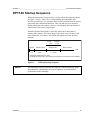
DPT146 Startup Sequence..................................................... 19
CHAPTER 4
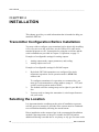
INSTALLATION ............................................................................................ 20
Transmitter Configuration Before Installation .................... 20
Selecting the Location ........................................................... 20
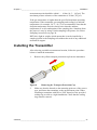
Installing the Transmitter ...................................................... 21
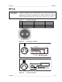
Wiring ...................................................................................... 23
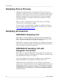
Sampling from a Process ...................................................... 24
Sampling Accessories ........................................................... 24

User's Guide _______________________________________________________________________
2 ____________________________________________________________________ M211372EN-E
DMT242SC Sampling Cell .................................................. 24
DMT242SC2 Sampling Cell with Swagelok Connectors ..... 24
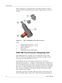
DSC74 Sampling Cell with Quick Connector and
Leak Screw .......................................................................... 25
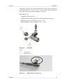
DSC74B Two-Pressure Sampling Cell ................................ 26
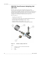
DSC74C Two-Pressure Sampling Cell with Coil ................. 28
DM240FA Duct Installation Flange ...................................... 30
CHAPTER 5
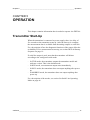
OPERATION ................................................................................................. 31
Transmitter Start-Up ............................................................... 31
Serial Communication ............................................................ 32
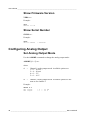
Connecting to the Serial Interface ....................................... 32
Installing the Driver for the USB Service Cable ............. 32
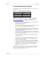
Terminal Application Settings .............................................. 33
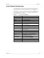
List of Serial Commands ....................................................... 35
Device Information ................................................................. 36
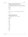
Show Device Information..................................................... 36
Show Currently Active Errors .............................................. 37
Show Command List ........................................................... 37
Show Firmware Version ...................................................... 38
Show Serial Number ............................................................ 38
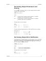
Configuring Analog Output ................................................... 38
Set Analog Output Mode ..................................................... 38
Set Analog Output Parameters and Scaling........................ 39
Set Analog Output Error Notification ................................... 39
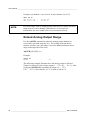
Extend Analog Output Range .............................................. 40
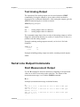
Test Analog Output .............................................................. 41
Serial Line Output Commands .............................................. 41
Start Measurement Output .................................................. 41
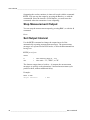
Stop Measurement Output .................................................. 42
Set Output Interval ............................................................... 42
Output a Reading Once ....................................................... 43
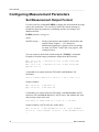
Configuring Measurement Parameters ................................ 44
Set Measurement Output Format ........................................ 44
Select Unit ........................................................................... 46
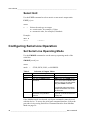
Configuring Serial Line Operation ........................................ 46
Set Serial Line Operating Mode .......................................... 46
Set Serial Line Settings ....................................................... 47
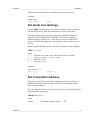
Set Transmitter Address ...................................................... 47
Set Serial Line Response Time ........................................... 48
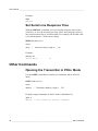
Other Commands.................................................................... 48
Opening the Transmitter in POLL Mode.............................. 48
Closing the Connection to a Transmitter in POLL Mode ..... 49
Show Transmitter Uptime .................................................... 49
Reset Transmitter ................................................................ 49
Restore Factory Settings ..................................................... 49
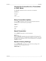
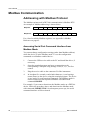
Modbus Communication ........................................................ 50
Addressing with Modbus Protocol ....................................... 50
Accessing Serial Port Command Interface from
Modbus Mode ................................................................. 50
Configuration Commands Related to Modbus ............... 51
CHAPTER 6

_________________________________________________________________________________
VAISALA _________________________________________________________________________ 3
MAINTENANCE ........................................................................................... 52
Periodic Maintenance ............................................................ 52
Cleaning .............................................................................. 52
Changing the Filter .............................................................. 52
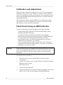
Calibration and Adjustment ................................................. 54
Field Check Using an MI70 Indicator .................................. 54
Repair Maintenance ............................................................... 56
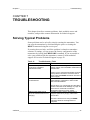
CHAPTER 7
TROUBLESHOOTING ................................................................................. 57
Solving Typical Problems...................................................... 57
Error Messages ...................................................................... 58
Unknown Serial Settings ....................................................... 58
Technical Support .................................................................. 59
Product Returns ..................................................................... 59
CHAPTER 8
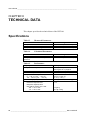
TECHNICAL DATA ...................................................................................... 60
Specifications ......................................................................... 60
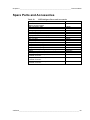
Spare Parts and Accessories ................................................ 63
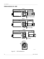
Dimensions in mm ................................................................. 64
APPENDIX A
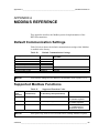
MODBUS REFERENCE ............................................................................... 65
Default Communication Settings .......................................... 65
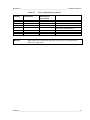
Supported Modbus Functions .............................................. 65
Modbus Register Map ............................................................ 66

User's Guide _______________________________________________________________________
4 ____________________________________________________________________ M211372EN-E
List of Figures
Figure 1 DPT146 with ISO G1/2” Thread ............................................... 12
Figure 2 DPT146 Transmitter Structure .................................................. 13
Figure 3 Cable with Threaded Connector ............................................... 14
Figure 4 USB Service Cable ................................................................... 14
Figure 5 Nokeval 301 Loop-Powered Display ........................................ 15
Figure 6 MPS1 Sensor ............................................................................ 16
Figure 7 DPT146 Startup Sequence ....................................................... 19
Figure 8 Removing the Transport Protection Cap .................................. 21
Figure 9 Installing the Transmitter .......................................................... 22
Figure 10 Tightening with a Wrench ......................................................... 22
Figure 11 Connectors I and II ................................................................... 23
Figure 12 Connector Pinout ...................................................................... 23
Figure 13 Sampling Cells DMT242SC2 (left) and DMT242SC (right) ...... 25
Figure 14 DSC74 Sampling Cell with Accessories ................................... 26
Figure 15 DSC74B .................................................................................... 27
Figure 16 Removing the Leak Screw ........................................................ 27
Figure 17 Default Assembly of DSC74C .................................................. 28
Figure 18 Alternative Assembly of DSC74C (for Tight Spaces) ............... 29
Figure 19 DM240FA with DPT146 ............................................................ 30
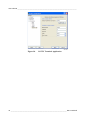
Figure 20 PuTTY Terminal Application ..................................................... 34
Figure 21 Opening the Filter ..................................................................... 53
Figure 22 Filter Structure .......................................................................... 53
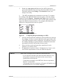
Figure 23 Comparing Dewpoint Readings on MI70 .................................. 55
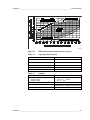
Figure 24 DPT146 Dewpoint Measurement Accuracy ............................. 61
Figure 25 DPT146 Dimensions ................................................................. 64

_________________________________________________________________________________
VAISALA _________________________________________________________________________ 5
List of Tables
Table 1 Manual Revisions ....................................................................... 7
Table 2 Related Manuals ........................................................................ 7
Table 3 Output Parameters of DPT146 ................................................. 11
Table 4 Connector Pinouts .................................................................... 23
Table 5 Default Serial Interface Settings ............................................... 33
Table 6 List of Serial Commands .......................................................... 35
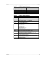
Table 7 FORM Command Parameters ................................................. 45
Table 8 FORM Command Modifiers...................................................... 45
Table 9 Selection of Output Modes ....................................................... 46
Table 10 Configuration commands for Modbus RTU .............................. 51
Table 11 Troubleshooting Table .............................................................. 57
Table 12 Error Messages ........................................................................ 58
Table 13 Measured Parameters .............................................................. 60
Table 14 Calculated Parameters ............................................................. 60
Table 15 Performance ............................................................................. 60
Table 16 Operating Environment ............................................................ 61
Table 17 Outputs ..................................................................................... 61
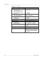
Table 18 General ..................................................................................... 62
Table 19 DPT146 Spare Parts and Accessories ..................................... 63
Table 20 Default Communication Settings .............................................. 65
Table 21 Supported Function Codes....................................................... 65
Table 22 Modbus Register Map ............................................................. 66
Table 23 Device Identification Objects .................................................... 67

User's Guide _______________________________________________________________________
6 ____________________________________________________________________ M211372EN-E
CHAPTER 1
GENERAL INFORMATION
This chapter provides general notes for the manual and the DPT146.
About This Manual
This manual provides information for installing, operating, and
maintaining Vaisala Dewpoint and Pressure Transmitter DPT146 for
Compressed Air.
Contents of This Manual
This manual consists of the following chapters:
- Chapter 1, General Information, provides general notes for the manual
and the DPT146.
- Chapter 2, Product Overview, This chapter introduces the features,
advantages, and product options.
- Chapter 3, Functional Description, describes the functionality of the
DPT146.
- Chapter 4, Installation, provides you with information that is intended
to help you install the DPT146.
- Chapter 5, Operation, contains information that is needed to operate
the DPT146.
- Chapter 6, Maintenance, provides information that is needed in basic
maintenance of the DPT146.
- Chapter 7, Troubleshooting, describes common problems, their
probable causes and remedies, and provides contact information for
technical support.
- Chapter 8, Technical Data, provides the technical data of the DPT146.

Chapter 1 _________________________________________________________ General Information
VAISALA _________________________________________________________________________ 7
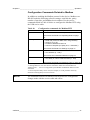
Version Information
Table 1 Manual Revisions
Manual Code
Description
M211372EN-E
June 2015. This manual. Updated technical
specification. Applicable from software version
1.4.0 onward.
M211372EN-D
August 2014. Previous version. Added a minimum
baud rate requirement when using the Modbus
protocol. Added a packing recommendation for
return shipment.
Related Manuals
Table 2 Related Manuals
Manual Code
Manual Name
M211370EN
DPT146 Quick Guide
Documentation Conventions
Throughout the manual, important safety considerations are highlighted
as follows:
WARNING
Warning alerts you to a serious hazard. If you do not read and follow
instructions
very carefully at this point, there is a risk of injury or even
death.
CAUTION
Caution warns you of a potential hazard. If you do not read and follow
instructions carefully at this point, the product could be damaged or
important data could be lost.
NOTE
Note highlights important information on using the product.

User's Guide _______________________________________________________________________
8 ____________________________________________________________________ M211372EN-E
Safety
The DTP146 delivered to you has been tested for safety and approved as
shipped from the factory. Note the following precautions:
CAUTION
Do not modify the unit. Improper modification can damage the product
or lead to malfunction.
CAUTION
The transmitter body does not have user serviceable parts inside, and is
not designed to be opened. Opening the transmitter will void the
warranty.
ESD Protection
Electrostatic Discharge (ESD) can cause immediate or latent damage to
electronic circuits. Vaisala products are adequately protected against
ESD for their intended use. It is possible to damage the product,
however, by delivering electrostatic discharges when touching,
removing, or inserting any objects inside the equipment housing.
To make sure you are not delivering high static voltages yourself:
- Handle ESD sensitive components on a properly grounded and
protected ESD workbench.
- When an ESD workbench is not available, ground yourself to the
equipment chassis with a wrist strap and a resistive connection cord.
- If you are unable to take either of the above precautions, touch a
conductive part of the equipment chassis with your other hand before
touching ESD sensitive components.
- Always hold component boards by the edges and avoid touching the
component contacts.

Chapter 1 _________________________________________________________ General Information
VAISALA _________________________________________________________________________ 9
Recycling
Recycle all applicable material.
Dispose of the unit according to statutory regulations. Do not dispose of
with regular
household refuse.
Regulatory Compliances
The Vaisala Dewpoint and Pressure Transmitter DPT146 for Compressed
Air is in conformity with the provisions of the following EU directive(s):
- EMC Directive
Conformity is shown by compliance with the following standards:
- EN 61326-1: Electrical equipment for measurement, control, and
laboratory use – EMC requirements – for use in industrial locations.
- EN 550022: Information technology equipment – Radio disturbance
characteristics – Limits and methods of measurement.
Trademarks
BAROCAP® and DRYCAP® are registered trademarks of Vaisala Oyj.
Windows® is a registered trademark of Microsoft Corporation in the
United States and/or other countries.
Software License
This product contains software developed by Vaisala. Use of the software
is governed by license terms and conditions included in the applicable
supply contract or, in the absence of separate license terms and
conditions, by the General License Conditions of Vaisala Group.

User's Guide _______________________________________________________________________
10 ___________________________________________________________________ M211372EN-E
Warranty
Visit our Internet pages for standard warranty terms and conditions:
www.vaisala.com/warranty.
Please observe that any such warranty may not be valid in case of
damage due to normal wear and tear, exceptional operating conditions,
negligent handling or installation, or unauthorized modifications. Please
see the applicable supply contract or Conditions of Sale for details of the
warranty for each product.

Chapter 2 ___________________________________________________________ Product Overview
VAISALA ________________________________________________________________________ 11
CHAPTER 2
PRODUCT OVERVIEW
This chapter introduces the features, advantages, and product options.
Introduction to DPT146
Vaisala Dewpoint and Pressure Transmitter DPT146 for Compressed Air
combines online measurement of dewpoint and pressure. The dewpoint
measurement is continuously pressure compensated using the measured
pressure. Temperature output is also available if the transmitter has been
ordered with serial line output.
DPT146 also calculates two other parameters, ppm moisture by volume
and dewpoint in atmospheric pressure. The transmitter’s compact size
makes it well suited for integration into OEM systems.
Table 3 Output Parameters of DPT146
Parameter
Abbreviation
Metric Unit
Non-Metric
Unit
Dewpoint/frost point temperature*
Tdf
ºC
ºF
Dewpoint/frost point temperature*,
converted to atmospheric pressure
Tdfatm
ºC
ºF
ppm moisture, by volume
H2O
ppm
ppm
Pressure, absolute
P
bara
psia
Temperature**
T
ºC
ºF
* When the dewpoint is below 0 °C, the transmitter outputs frost point for T
d
** Available if RS-485 only output is selected

User's Guide _______________________________________________________________________
12 ___________________________________________________________________ M211372EN-E
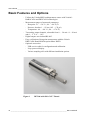
Basic Features and Options
- Utilizes the Vaisala MPS1 multiparameter sensor with Vaisala’s
BAROCAP® and DRYCAP® technologies.
- Measurement ranges of measured parameters:
- Dewpoint -70 ... +30 °C (-94 ... +86 °F) T
d
- Pressure, absolute 1 ... 12 bar (14.5 ... 174 psi)
- Temperature -40 ... +80 °C (-40 ... +176 °F)
- Two analog output channels, selectable from 0 … 20 mA / 4 ... 20 mA
and 0 … 5 V / 0 … 10 V.
- Digital output: non-isolated RS-485.
- Easy verification of dewpoint measurement with the Vaisala
DRYCAP® Hand-Held Dewpoint Meter DM70.
- Optional accessories:
- USB service cable for configuration and calibration.
- Loop-powered display.
- Various sampling cells with different installation options.
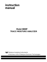
1109-029
Figure 1 DPT146 with ISO G1/2” Thread

Chapter 2 ___________________________________________________________ Product Overview
VAISALA ________________________________________________________________________ 13
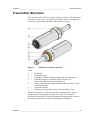
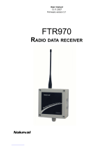
Transmitter Structure
The structure of the DPT146 is shown in Figure 2 below. The transmitter
body does not have user serviceable parts inside, and is not designed to
be opened. Opening the transmitter will void the warranty.
1109-031
Figure 2 DPT146 Transmitter Structure
where
1
=
30 mm nut
2
=
Transmitter body
3
=
4-pin M8 connector I: analog outputs and operating power
4
=
4-pin M8 connector II (shown with protective cap):
Non-isolated RS-485 and operating power
5
=
Sealing ring (included with transmitters that have ISO or UNF
connection thread)
6
=
Connection thread
7
=
Stainless steel mesh filter that protects the MPS1 sensor
When the transmitter is delivered, the filter is protected by a yellow
transport protection cap that keeps the sensor dry. The transport
protection cap should be left on the transmitter during storage. Remove
the transport protection cap before installing the transmitter.

User's Guide _______________________________________________________________________
14 ___________________________________________________________________ M211372EN-E
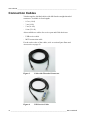
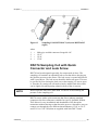
Connection Cables
Vaisala supplies shielded cables with M8 female straight threaded
connector. Available in four lengths:
- 0.3 m (1.0 ft)
- 3 m (9.8 ft)
- 5 m (16.4 ft)
- 10 m (32.8 ft)
Also available are cables for service port and field check use:
- USB service cable
- MI70 connection cable
For the order codes of the cables, refer to section Spare Parts and
Accessories on page 63.
0910-135
Figure 3 Cable with Threaded Connector
0809-002
Figure 4 USB Service Cable

Chapter 2 ___________________________________________________________ Product Overview
VAISALA ________________________________________________________________________ 15
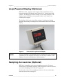
Loop-Powered Display (Optional)
DPT146 with 4 ... 20 mA current output can be connected to a loop-
powered external LED display (type Nokeval 301, Vaisala order code
226476). The display provides a reading of one output parameter. The
display is powered by the current signal, so there is no need for an
external power supply.
The display is delivered at its default settings. Configure the display
functions and scaling according to the documentation delivered with the
display.
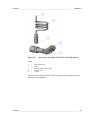
1102-053
Figure 5 Nokeval 301 Loop-Powered Display
NOTE
The loop resistance of the display must be included in the loop resistance
calculation for the complete current loop. For the loop resist
ance of the
display, refer to the manufacturer’s documentation.
Sampling Accessories (Optional)
DPT146 is compatible with various sampling accessories. For more
information on performing sampling, and a description of the accessories,
see section Sampling from a Process on page 24.
For the order codes of the sampling accessories, refer to section Spare
Parts and Accessories on page 63.

User's Guide _______________________________________________________________________
16 ___________________________________________________________________ M211372EN-E
CHAPTER 3
FUNCTIONAL DESCRIPTION
This chapter describes the functionality of the DPT146.
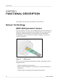
Sensor Technology
MPS1 Multiparameter Sensor
DPT146 combines Vaisala’s proven DRYCAP® sensor technology for
industrial dewpoint measurement with BAROCAP® pressure sensor
technology. Both technologies are integrated on the same MPS1
multiparameter sensor element, allowing for a highly compact and
versatile transmitter.
1109-037
Figure 6 MPS1 Sensor
There are several important advantages in using a transmitter with an
integrated sensor:
- Reduces installation work and cost.
- Improves the leak tightness of the system as connection points are
minimized.
- Enables online monitoring of all supported parameters.

Chapter 3 _______________________________________________________ Functional Description
VAISALA ________________________________________________________________________ 17
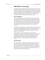
DRYCAP® Technology
Vaisala DRYCAP® dewpoint measurement technology ensures accurate
measurement with excellent long term stability. This results in very low
maintenance requirements for the transmitter. The lasting performance is
achieved with microprocessor technology and software that automatically
performs self-diagnostic functions in addition to the normal dewpoint
measurement. The self-diagnostic procedures that are conducted are
called auto-calibration, sensor purge, and sensor warming.
Auto-Calibration
The auto-calibration feature of the MPS1 multiparameter sensor is an
automatic procedure which greatly reduces the possible drift in the dry
end of the dewpoint measurement. During auto-calibration the sensor is
warmed for a short period (< 1 min) and the sensor capacitance values
are evaluated at the elevated temperature. The possible dry end drift is
then corrected to correspond to the calibrated values. During the auto-
calibration the transmitter outputs the dewpoint value prior to the
procedure.
The transmitter performs the auto-calibration after the start-up purge, and
at one hour intervals during normal operation. When measuring very dry
conditions, the transmitter performs the auto-calibration at shorter
intervals. A significant change in dewpoint or temperature may also
trigger the auto-calibration.
Auto-calibration is carried out only if several criteria for the
measurement environment are fulfilled. This ensures the reliability of the
adjustments, and maintains the excellent long term stability. These
criteria include, for example, a stable enough moisture level in the
measured atmosphere. If the conditions are not fulfilled, the auto-
calibration function is postponed until satisfactory conditions are
reached.
Sensor Purge
Sensor purge is also an automatic procedure that minimizes the drift at
the wet end readings of the dewpoint measurement. Sensor purge is
performed once a day, and five minutes after the power is switched on.
The sensor is heated for several minutes which will then evaporate all
excess molecules out of the sensor polymer. This, together with the auto-
calibration, results in a very small drift of the sensor due to the very
linear behavior of the polymer technology.

User's Guide _______________________________________________________________________
18 ___________________________________________________________________ M211372EN-E
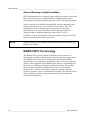
Sensor Warming in High Humidities
DPT146 transmitter has a warming feature which prevents the sensor and
filter from becoming wet in high humidities. High humidity may be
present when the dewpoint temperature rises close to the gas temperature.
Sensor warming is switched on automatically when the humidity in the
measured gas increases to a level where dew can start to form. The
advantage of sensor warming is the rapid response of dewpoint
measurement. A wet sensor and filter would otherwise result in a
dewpoint equal to ambient temperature (that is RH = 100 %).
If in spite of sensor warming the sensor gets soaked, it will recover fully
back to normal operation after it dries out.
NOTE
Sensor warming is not available if the transmitter has been ordered with
RS-485 only output.
BAROCAP® Technology
The BAROCAP® silicon capacitive absolute pressure sensor was
developed by Vaisala for barometric pressure measurement applications.
The BAROCAP® sensor has excellent hysteresis and repeatability
characteristics, low temperature dependence, and a very good long-term
stability. The ruggedness of the BAROCAP® sensor is outstanding and
the sensor is resistant to mechanical and thermal shocks. The pressure
measurement of the MPS1 multiparameter sensor is based on an
advanced RC oscillator and reference capacitors against which the
capacitive pressure sensor is continuously measured. The microprocessor
of the transmitter performs compensation for pressure linearity and
temperature dependence.
Page is loading ...
Page is loading ...
Page is loading ...
Page is loading ...
Page is loading ...
Page is loading ...
Page is loading ...
Page is loading ...
Page is loading ...
Page is loading ...
Page is loading ...
Page is loading ...
Page is loading ...
Page is loading ...
Page is loading ...
Page is loading ...
Page is loading ...
Page is loading ...
Page is loading ...
Page is loading ...
Page is loading ...
Page is loading ...
Page is loading ...
Page is loading ...
Page is loading ...
Page is loading ...
Page is loading ...
Page is loading ...
Page is loading ...
Page is loading ...
Page is loading ...
Page is loading ...
Page is loading ...
Page is loading ...
Page is loading ...
Page is loading ...
Page is loading ...
Page is loading ...
Page is loading ...
Page is loading ...
Page is loading ...
Page is loading ...
Page is loading ...
Page is loading ...
Page is loading ...
Page is loading ...
Page is loading ...
Page is loading ...
Page is loading ...
Page is loading ...
-
 1
1
-
 2
2
-
 3
3
-
 4
4
-
 5
5
-
 6
6
-
 7
7
-
 8
8
-
 9
9
-
 10
10
-
 11
11
-
 12
12
-
 13
13
-
 14
14
-
 15
15
-
 16
16
-
 17
17
-
 18
18
-
 19
19
-
 20
20
-
 21
21
-
 22
22
-
 23
23
-
 24
24
-
 25
25
-
 26
26
-
 27
27
-
 28
28
-
 29
29
-
 30
30
-
 31
31
-
 32
32
-
 33
33
-
 34
34
-
 35
35
-
 36
36
-
 37
37
-
 38
38
-
 39
39
-
 40
40
-
 41
41
-
 42
42
-
 43
43
-
 44
44
-
 45
45
-
 46
46
-
 47
47
-
 48
48
-
 49
49
-
 50
50
-
 51
51
-
 52
52
-
 53
53
-
 54
54
-
 55
55
-
 56
56
-
 57
57
-
 58
58
-
 59
59
-
 60
60
-
 61
61
-
 62
62
-
 63
63
-
 64
64
-
 65
65
-
 66
66
-
 67
67
-
 68
68
-
 69
69
-
 70
70


Vaisala DPT146 User manual
- Category
- Measuring, testing & control
- Type
- User manual
Ask a question and I''ll find the answer in the document
Finding information in a document is now easier with AI
Related papers
Other documents
-
Omega RH200A & RH201A Owner's manual
-
Ludlum Measurements 9-4 Control Software Owner's manual
-
 Nokeval DCS770 User manual
-
Pyle PTHM20 User manual
-
-
 Alpha Moisture Systems dewSMART DS1000 User manual
-
 Teledyne 8800P User manual
-
 Nokeval FTR970 User manual
-
Logicbus T203PM100-MU User manual
-
Marathon F200060 User manual


