Page is loading ...

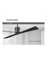
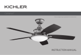
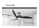
INSTRUCTION MANUAL
Product images may vary slightly from actual product.
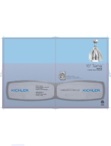
56” ICON CEILING FAN
Model #300395
READ AND SAVE THESE INSTRUCTIONS

KICHLER.COM
Net Weight: 8.63 kg (19.02 lb)
Gross weight: 10.45 kg (23.04 lb)

56” ICON | 3
SAFETY RULES
TOOLS AND MATERIALS REQUIRED
PACKAGE CONTENTS
MOUNTING OPTIONS
HANGING THE FAN
INSTALLATION OF SAFETY SUPPORT
(CANADA ONLY)
ELECTRICAL CONNECTIONS
FINISHING THE INSTALLATION
ATTACHING THE FAN BLADE ARMS
ATTACHING THE FAN BLADES
INSTALLING THE LIGHT KIT FIXTURE
INSTALLING GLASS SHADE
CONTROL SYSTEM SET-UP
BUTTON INSTRUCTIONS
INSTALLING WALL PLATE
INSTALLING THE TRANSMITTER
OPERATING INSTRUCTIONS
TROUBLESHOOTING
FCC INFORMATION
TABLE OF CONTENTS
Read all instructions BEFORE assembly and USE of product
KEEP INSTRUCTIONS FOR FUTURE USE
4
6
6
7
8
11
12
14
15
15
16
16
17
19
20
21
22
23
24

| KICHLER.COM
4
SAFETY RULES
WARNING: FOR CANADA, THIS FAN MUST BE SECURED
DIRECTLY TO THE BUILDING STRUCTURE/CEILING
JOIST. DON’T SECURE THIS FAN TO AN OUTLET BOX.
1. CAUTION - RISK OF SHOCK -
Disconnect power at the main circuit breaker panel
or main fusebox before starting and during the
installation.
2. WARNING: This fixture is intended for installation in
accordance with the National Electrical Code (NEC) and
all local code specifications. If you are not familiar with
code requirements, installation by a certified electrician
is recommended.
3. WARNING: To reduce the risk of fire, electric shock, only
use the control provided with fan.
4. WARNING: To reduce the risk of fire, electric shock,
or Personal Injury mount to an outlet box marked
“Acceptable For Fan Support of up to 15.9 kg (35 lb)”.
For outlet box mounting, use mounting screws (and
lock washers) provided with the outlet box. Most outlet
boxes commonly used for the support of light fixtures
are not acceptable for fan support and may need to
be replaced. Due to the complexity of the installation
of this fan, a qualified licensed electrician is strongly
recommended.”
5. All wiring must be in accordance with the National
Electrical Code ANSI/NFPA 70 and local electrical codes.
Electrical installation should be performed by a qualified
licensed electrician.
6. The outlet box and support structure must be securely
mounted and capable of reliably supporting a minimum of
15.9 kg (35 lb). Use only CUL Listed outlet boxes marked
“FOR FAN SUPPORT”.
WARNING: TO REDUCE THE RISK OF FIRE, ELECTRIC
SHOCK OR PERSONAL INJURY, MOUNT FAN TO OUTLET
BOX MARKED “ACCEPTABLE FOR FAN SUPPORT”.
7. CAUTION: The fan must be mounted with a minimum
of 2.1m (7 feet) clearance from the trailing edge of the
blades to the floor.
8. To operate the reverse function on this fan, press the
reverse button while the fan is running.
9. Avoid placing objects in the path of the blades.
10. To avoid personal injury or damage to the fan and other
items, be cautious when working around or cleaning the
fan.
11. WARNING: Make sure the power is disconnected before
cleaning the fan.
READ AND SAVE THESE INSTRUCTIONS

56” ICON | 5
12. Do not use water or detergents when cleaning the fan
or fan blades. A dry dust cloth or lightly dampened
cloth will be suitable for most cleaning.
13. After making the electrical connections, spliced
conductors should be turned upward and pushed
carefully up into outlet box. The wires should be
spread apart with the grounded conductor and the
equipment-grounding conductor on one side of the
outlet box and the ungrounded conductor on the
other side of the outlet box.
14. Electrical diagrams are reference only. Light Kits
that are not packed with the fan must be cULus listed
and marked suitable for use with the model fan you
are installing. Switches must be cULus General Use
Switches. Refer to the Instructions packaged with the
light kits and switches for proper assembly.
15. All set screws must be checked, and re-tightened
where necessary, before installation.
WARNING: TO REDUCE THE RISK OF PERSONAL INJURY,
DO NOT BEND THE BLADE BRACKETS (ALSO REFERRED
TO AS BLADE ARMS) DURING ASSEMBLY OR AFTER
INSTALLATION. DO NOT INSERT OBJECTS IN THE PATH
OF BLADES.
16. WARNING: Chemical Burn Hazard. Keep batteries
away from children.; and
This product contains a lithium button/coin cell
battery. If a new or used lithium button/coin cell
battery is swallowed or enters the body, it can cause
severe internal burns and can lead to death in as little
as 2 hours. Always completely secure the battery
compartment. If the battery compartment does
not close securely, stop using the product, remove
the batteries, and keep it away from children. If you
think batteries might have been swallowed or placed
inside any part of the body, seek immediate medical
attention.
a) The cells shall be disposed of properly, including
keeping them away from children; and
b) Even used cells may cause injury.
SAFETY RULES (continued)
!

| KICHLER.COM
6
TOOLS REQUIRED PACKAGE CONTENTS
• Philips screw driver
• Blade screw driver
• 11mm wrench
• Step ladder
• Wire cutters
Unpack your fan and check the contents.
You should have the following items:
a. Fan blades (5)
b. Canopy
c. Ball/Downrod assembly
d. Coupling cover
e. Fan motor assembly
f. Blade arms (5)
g. Light kit assembly
h. Glass shade assembly
i. Receiver
j. Wall transmitter
k. Parts bag contents:
1) Mounting hardware:
Star washers (2), wire nuts (3),
machine screws (2), washers (2),
wood screws (2)
2) Blade attachment hardware:
blade screws (16), blade arm
screws (11), fiber washers (16)
3) Safety cable hardware:
wood screw, lock washer, flat
washer
4) Balancing kit
a.
b.
c.
d.
e.
f.
g.
h.
i.
j.
k.

56” ICON | 7
Outlet box
Provide strong
support
Recessed
outlet box Ceiling
mounting plate
Outlet box
Outlet box
ANGLED CEILING
MAXIMUM 20°
ANGLE
MOUNTING OPTIONS
If there isn’t an existing UL (cUL for Canadian Installation) listed
mounting box, then read the following instructions. Disconnect the
power by removing fuses or turning o circuit breakers.
Secure the outlet box directly to the building structure. Use
appropriate fasteners and building materials. The outlet box and its
support must be able to fully support the full weight of the fan (up
to 15.9 kg (35 lb)). Do not use plastic outlet boxes.
Figures 1, 2, and 3 are examples of dierent ways to mount the
outlet box.
NOTE: If you are installing the ceiling fan on a sloped (vaulted)
ceiling, you may need a longer downrod to maintain proper
clearance between the tip of the blade and the ceiling. A minimum
clearance of 12” is suggested for optimal operation.
NOTE: Depending on the location you have selected for
installation, you may need to purchase and install a “Joist Hanger”
for the support of the outlet box. Make sure the joist hanger you
purchase has been designed for use with ceiling fans. (Fig. 4)
Fig. 2
Fig. 1
Fig. 3
Fig. 4

| KICHLER.COM
8
HANGING THE FAN
NOTE: FOR CANADA, THIS FAN MUST BE SECURED DIRECTLY
TO THE BUILDING STRUCTURE/CEILING JOIST. DON’T SECURE
THIS FAN TO AN OUTLET BOX. (see Fig. 6A)
REMEMBER to turn o the power before you begin.
To properly install your ceiling fan, follow the steps below.
Step 1. Remove the decorative canopy bottom cover from the
canopy by turning the cover counterclockwise. (Fig. 5)
Step 2. Remove the ceiling mounting bracket from the canopy by
removing (and save) one of the two screws. Loosen the remaining
screw by a half turn. (Fig. 5)
Step 3. Pass the 120 volt supply wires from the ceiling outlet box
through the center of the ceiling mounting bracket. (Fig. 6)
Step 4. Attach the ceiling mounting bracket to the outlet box using
the screws and washers included with the outlet box. (Fig. 6)
Step 4A. Secure the mounting bracket directly to a joist from the
building structure. Use only the appropriate wood screws and lock
washers included with your fan. (Fig. 7)
NOTE: THIS STEP IS ONLY FOR CANADA.
CAUTION: The hanger bracket must be installed directly to the
building joist using the two wood screws and washers provided.
(Fig. 7)
Fig. 6
Fig. 5
Fig. 7
Ceiling
mounting
bracket
Canopy
Canopy cover
120V Wires
Ceiling
hanger
bracket
Mounting screws
(supplied with electrical box)
UL Listed
electrical box
Washers
120V Wires
Hanger bracket
Ceiling joist
#10 Wood screws
Lock washers

56” ICON | 9
Step 5. Remove the hanger ball from the downrod assembly by
loosening the set screw, unscrewing and removing the cross pin and
unscrewing the ball o the rod. (Fig. 8)
Step 6. Loosen the two set screws and remove the hitch pin and
retaining clip from the coupling on top of the motor assembly. (Fig. 9)
Step 7. Carefully feed the electrical lead wires from the fan up
through the downrod. Thread the downrod into the coupling until the
hitch pin holes align.
Next, replace the hitch pin and retaining clip. Tighten both set screws.
(Fig. 9)
Fig. 8
Fig. 9
HANGING THE FAN (continued)
Cross pin
Hanger ball
Downrod
Supply wire &
Safety cable
Downrod
Retaining
clip
Hitch pin
Set screws
Coupling
Set screws

| KICHLER.COM
10
Step 8. Slip the coupling cover, canopy cover and canopy onto the
downrod. (Fig. 10)
Thread the hanger ball onto the downrod, insert the cross pin
through the downrod and tighten. Tighten the set screw.
Step 9. Lift the motor assembly into position and place the
hanger ball into the ceiling mounting bracket.
Rotate the entire assembly until the “Check Tab” has dropped into
the “Registration Slot” and seats firmly. (Fig. 11)
The entire motor assembly should not rotate (left or right) when
seated properly.
WARNING: Failure to reattach the cross pin and seat the
“Check Tab” can cause the fan to fall from the ceiling during
operation. Take special care to make sure this pin is reattached.
HANGING THE FAN (continued)
Registration
slot
Check
tab
Cross pin
Hanger ball
Set screw
Downrod
Coupling
Canopy
Canopy cover
Coupling cover
Supply wires & Safety cable
Fig. 10
Fig. 11

56” ICON | 11
INSTALLATION OF SAFETY SUPPORT
(Required for Canadian installation ONLY)
A safety support cable is provided to help prevent the ceiling fan
from falling, please install it as follows.
Step 1. Attach the provided wood screw and washers to the ceiling
joist next to the mounting bracket but do not tighten. (Fig. 12)
Step 2. Adjust the length of the safety cable to reach the screw and
washers by pulling the extra cable through the cable clamp until the
overall length is correct, put the end of the cable back through the
cable clamp, forming a loop at the end of the cable. Tighten the cable
clamp securely. Now, put the loop in the end of the safety cable over
the wood screw securely.
NOTE: Although the safety support cable is required for Canadian
installations only, it’s a good idea to make the attachment with
any installation.
Fig. 12
Hanger bracket
Safety cable Attach safety cable
to ceiling joist with
screw and washer

| KICHLER.COM
12
ELECTRICAL CONNECTIONS
WARNING: Carefully read and retain this Instruction Manual for
future reference.
WARNING: To avoid possible electrical shock, be sure the
electricity is turned o at the main panel by removing the fuse or
opening the circuit breaker.
WARNING: This control is designed for use with “DC Motor
Ceiling Fans” ONLY. DO NOT use with any other type of electrical
appliance.
WARNING: All wiring must conform to national and local electrical
codes. If you feel you do not have enough electrical knowledge,
have a licensed electrician install the control.
Step 1. Insert the receiver into the ceiling mounting bracket with the
flat side of the receiver facing the ceiling. (Fig. 13)
For best performance, make sure the Black antenna, on the end
of the receiver, remains extended and not tangled with any of the
electrical wires. Fig. 13
Receiver
Hanger
bracket

56” ICON | 13
Fig. 14
White (Neutral)
Green or Bare
Copper (Ground)
White ("AC IN N")
Outlet box
Black (Hot)
Black ("AC IN L")
Receiver
Blue (For light)
Green-
(ground)
Orange (Motor)
Brown (Motor)
Grey(Motor)
(Connect to ground
wire on hanger
bracket if no house
ground wired)
Filter
White (For light)
A. Fan wire connection (Fig. 14)
Connect the orange wire from the fan to the orange wire on the receiver.
Connect the brown wire from the fan to the brown wire on the receiver.
Connect the grey wire from the fan to the grey wire on the receiver.
Connect the blue wire from the fan to the blue wire on the receiver.
Connect the white wire from the fan to the white wire on the receiver.
Secure the wire connections with the plastic wire nuts provided.
Align the black wire from the receiver to the brown wire from the filter,
align the white wire from the receiver to the blue wire from the filter, then
connecting the molded adaptor together.
Connect the black (hot) wire from the ceiling to the brown wire from the
filter box.
Connect the white (Neutral) wire from the ceiling to the blue wire from the
filter box.
Secure the wire connections with the plastic wire nuts provided.
If your outlet box has a ground wire (green or bare copper) connect it to
the fan ground wires; otherwise connect the hanging bracket ground
wire to the mounting bracket. Secure the wire connection with a plastic
nut provided. After connecting the wires, spread them apart so that the
green and white wires are on one side of the outlet box and black and blue
wires are on the other side. Carefully tuck the wire connections up into the
outlet box.
NOTE: Remember to cut o excess lead wire from fan body before wiring
in order to install receiver and canopy easily.
ELECTRICAL CONNECTIONS (continued)

| KICHLER.COM
14
FINISHING THE INSTALLATION
Step 1. Tuck all the connections neatly into the ceiling outlet box.
Step 2. Slide the canopy up to the mounting bracket and place one of
the key hole slots over the mounting screw on the mounting bracket.
Rotate the canopy until the screw head locks in place at the narrow
section of the key hole. (Fig.15)
Step 3. Align the remaining circular hole on the canopy with the
remaining hole on the Ceiling Mounting Bracket. Insert and tighten
the mounting screw you removed earlier and the mounting screw
from step 2 above. Now, attach the canopy cover to the mounting
screw heads by inserting the screw heads into the bottom side of the
canopy cover and rotating the cover clockwise.
NOTE: Adjust the canopy screws as necessary until the canopy
and canopy cover are snug.
WARNING: Make sure the “Check Tab” at the bottom of the
hanger bracket is properly seated in the “Registration Slot” on
the side of the hanger ball before attaching the canopy to the
bracket. Failure to properly seat the “Check Tab” could damage
the electrical wires when the ceiling fan blade direction is changed
while the fan is running.
Fig. 15
Outlet box
Ceiling
mounting
bracket
Canopy
Canopy
cover
Screw
Screw
Filter Receiver

56” ICON | 15
ATTACHING THE FAN BLADES
Step 1. Align the holes from the blade and washer to the holes from
the blade arms, and secure the blade in place with screws provided.
(Fig. 17)
Step 2. Repeat these steps for the remaining four blades.
Fig. 16
Fig. 17
ATTACHING THE FAN BLADE ARMS
Step 1. Fasten the blade arm to the fan motor assembly by tightening the
blade arm screw onto the fan motor assembly. (Fig. 16)
Step 2. Repeat this procedure for the remaining four blade arms.
Screw
Fan motor assembly
Blade arm
Fan motor assembly
Blade
Screw
Washer

| KICHLER.COM
16
INSTALLING THE GLASS SHADE
Raise the glass shade against the light plate and secure by tightening
the nut and finial. (Fig. 20)
Fig. 19
Fig. 20
Fig. 18
INSTALLING THE LIGHT KIT FIXTURE
CAUTION: “To reduce the risk of electric shock, disconnect the
electrical supply circuit to the fan before installing light kit.”
Step 1. Remove the finial, and nut from the threaded nipple of the
light kit fixture assembly. (Fig. 18)
Step 2. Loosen, remove, and save the four screws on the mounting
ring, attached to the motor shaft. Connect the wire from the light
kit fixture assembly to the wire from the fan motor assembly by
connecting the molded adaptor plug together.
Step 3. Align the screw holes from the light kit pan with the screw
holes on the mounting ring of the fan motor assembly. Reinstall
and tighten the four screws previously removed in step 2 securely.
(Fig. 19)
Light kit pan
Screws
Fan motor assembly
Finial
Light kit pan
Nut
Fan motor
assembly
Light kit pan
Shade
Finial
Nut
A
B

56” ICON | 17
WARNING:Chemical Burn Hazard.Keep
batteries away from children.See Manual
Model : UC7214T
FCC ID : CHQ7214T
WARNING:Chemical Burn Hazard.Keep
batteries away from children.See Manual
ON
Dip switch
Model : UC7214T
FCC ID : CHQ7214T
WARNING:Chemical Burn Hazard.Keep
batteries away from children.See Manual
CONTROL SYSTEM SET-UP
WARNING: Chemical Burn Hazard. Keep batteries away from
children.
WARNING: Make sure the power is completely disconnected
before you begin this procedure.
SPECIAL NOTE: Your new Kichler® Ceiling Fan is state of the art
and employs a high eciency DC (direct current) motor with an
advanced CoolTouch™ remote control system. The DC motor
uses 70% less energy than a conventional ceiling fan AC induction
motor. The DC motor is “digitally” controlled and operates
dierently than conventional ceiling fan motors.
Please read this portion of the manual completely before
proceeding.
Our CoolTouch™ Control System includes an “automatic
frequency selection” feature. To set the control frequency and
program the control system, follow these steps:
Open the back of the transmitter by loosening the screw (figure
21). The frequency selector is a “dip switch block” inside the
battery compartment of the transmitter (see figure 22). You
change frequencies by arranging the small switches numbered
1 through 4 in a up or down position. 16 Possible frequencies
or combinations are possible. The fifth switch, marked D and X
sets the system for operation with incandescent or fluorescent
lamps. It is essential to set this switch correctly. If your ceiling
fan is equipped with incandescent lamps set this switch to the D
position, for fluorescent lamps, set the switch to the X position.
If these settings are reversed, the lighting control system will
operate erratically and could damage your ceiling fan.
Fig. 21
Fig. 22
!
!

| KICHLER.COM
18
System programing: Read all of these steps before proceeding.
Each step must be followed exactly to properly program the control system.
1. You can leave the frequency switches at the factory setting or move them to any combination of up or
down. Use a small flat bladed screwdriver to move the switches.
2. Insert both batteries and make sure they are seated correctly in each recess with the positive + sign
facing up. Replace the battery cover. (Figure 21)
3. Test the transmitter by pushing and releasing ANY button briefly. A Blue Light should illuminate under
the 3-4 buttons. (Fig. 23) If not, check to make sure the batteries are inserted and seated correctly.
Power Up and Programming:
4. Follow the below steps to set the remote control:
The auto learning function will only mandate within 60 seconds when turning the fan’s AC power ON.
(Figure 24)
5. Select desired frequency from the back of transmitter.
6. From the back of the transmitter, press and hold the “hold ” button for 5+ seconds. Once the receiver
has detected the frequency, the light will flash twice, and the fan will automatically begin to operate
and start to rotate in the counter clockwise direction and on the highest RPM for 3 minutes. When
counterclockwise rotation has finished, the fan will automatically reverse to clockwise direction again
to the highest RPM for 3 minutes. Fan will shut o when the self calibration test has finished. The total
self calibration test will last about 6 minutes.
NOTE: If the self calibration test failed, turn the AC power o; restore power and process the self
calibration test again.
NOTE: During self calibration test, the remote is non-fuctional.
NOTE: The learning frequency function and self calibration test will continue to retain the last set
frequency and calibration set even when the AC power is shut o. If the frequency is changed the self
calibration test will occur again.
7. Your CoolTouch™ Control System is now programmed and ready for use. Please see the Operating
Instructions.
The receiver provides the following protective function:
1. Lock position: The DC motor has a built-in safety against obstruction during operation. If there is an
obstruction, the motor will stop and then the power will automatically go o in 30 seconds. Remove
the obstruction and reset.
2. Over 80W protection: When the receiver detects motor power consumption which is greater than
80W, the receiver power will be stopped and operation will immediately discontinue. Wait for 5 seconds
and then turn the receiver power back on.
Fig. 23
Fig. 24
Blue Light
Press/hold Button

56” ICON | 19
BUTTON INSTRUCTIONS
Figure 25
Buttons 1, 2, 3, 4, 5 and 6 are used to set the blade speed as follows:
1 = Low Speed
2 = Medium Low Speed
3 = Medium Speed
4 = Medium High Speed
5 = High Speed
6 = Extra High Speed
Figure 26
The “MOTOR OFF” button:
This button turns the fan motor o and is also used in the program procedure.
The “LIGHT CONTROL “ button:
This button turns the bottom light ON or OFF and also controls the brightness
setting. Press and hold either button to set the desired brightness level. The
next time you turn the light on, the system will remember this setting. Press
and release either button to turn the light ON or OFF.
Figure 27
The “FORWARD/REVERSE “ button is used to set the fan in forward or reverse
operation. Each time you press this button the fan blades will reverse direction.
This button functions ONLY when the fan blades are in motion.
OPERATIONAL NOTE: Each time you start the blades rotating, at any speed
or reverse, the direction of the blades the Control System will do a “Self Check”
to ensure operational integrity. The blades will rotate slowly a short distance
(¼ turn), pause, change directions, rotate ¼ turn, then build up RPM’S to the
selected speed.This is a perfectly normal procedure and ensures normal
operating performance Fig. 27
Fig. 25
Motor Off Button
Light Control Buttons
Forward/Reverse
Button
Speed Buttons
Fig. 26

| KICHLER.COM
20
INSTALLING THE COOL TOUCHTM
CONTROL SYSTEM WALL PLATE
Select a location to install the Wall Control System Transmitter and
Wall Plate.
WARNING: All wiring must be in accordance with the National
Electrical Code and local electrical codes. Electrical installation
should be performed by a qualified licensed electrician.
Select a location to install your CoolTouch™ Control System
Transmitter. You can replace an existing wall switch or, install the
transmitter on ANY flat surface.
Option 1: Install the control system using an existing wall switch
outlet box. Make sure the electrical power is TURNED OFF at the
main panel before continuing.
NOTE: Switch installation must comply with all local and national
electric codes.
Step 1. Remove the existing wall plate and the old switch from the
wall outlet box. Wire nut the BLACK leads (hot) together and push
back inside the outlet box. (Fig. 28)
Step 2. Install the metal plate and CoolTouch™ wall plate to the
existing wall outlet box with 4 screws provided. Then place the two
plastic plugs into the wall plate. (Fig. 29)
Option 2: Install the control system on ANY flat surface.
Select the desired location and use the CoolTouch™ wall plate to
mark the location for the mounting holes. Use the dry wall anchors
and/or screws provided and finish the installation.
Wall plate
Switch
Outlet box
Screws
Screws
Plastic plugs
CoolTouch
™
wall plate
Outlet box Metal plate
Fig. 29
Fig. 28
/