ORATH 2500- SPRVSR Supervisor Board User manual

Type
User manual

ORATH 2500- SPRVSR Supervisor Board is a high-quality emergency communication device designed for use in various commercial and industrial applications. With its advanced capabilities, this board offers a reliable and efficient solution for monitoring and managing emergency phone systems. The ORATH 2500- SPRVSR Supervisor Board features a user-friendly interface, allowing for easy setup and configuration. It supports a range of functions, including zone monitoring, alarm activation, and integration with external systems.

ORATH 2500- SPRVSR Supervisor Board is a high-quality emergency communication device designed for use in various commercial and industrial applications. With its advanced capabilities, this board offers a reliable and efficient solution for monitoring and managing emergency phone systems. The ORATH 2500- SPRVSR Supervisor Board features a user-friendly interface, allowing for easy setup and configuration. It supports a range of functions, including zone monitoring, alarm activation, and integration with external systems.

Supervisor Board
2500-__SPRVSR
Installation & Operations Manual
N56W24720 N. Corporate Circle Sussex, WI 53089
800-451-1460 www.rathcommunications.com
RP8500SPRVSR
Ver. 8
04/22
WARRANTY
2YEAR
Thank you for purchasing a RATH® Supervisor Board. We are the largest Emergency Communication
Manufacturer in North America and have been in business for over 35 years.
We take great pride in our products, service, and support. Our Emergency Products are of the highest
quality. Our experienced customer support teams are available to remotely assist with site preparation,
installation, and maintenance. It is our sincere hope that your experience with us has and will continue
to surpass your expectations.
Thank you for your business,
®
N56W24720 N. Corporate Circle Sussex, WI 53089
800-451-1460 www.rathcommunications.com
Table of Contents
Items Needed . . . . . . . . . . . . . . . . . . . . . . . . . . . . . . . .
Installation & System Wiring . . . . . . . . . . . . . . . . . . .
Connecting the Power Supply . . . . . . . . . . . . . . . . . .
Setting Switches . . . . . . . . . . . . . . . . . . . . . . . . . . . . .
Alarm Wiring . . . . . . . . . . . . . . . . . . . . . . . . . . . . . . . .
Mounting . . . . . . . . . . . . . . . . . . . . . . . . . . . . . . . . . . .
Complete System Connections . . . . . . . . . . . . . . . . .
Testing . . . . . . . . . . . . . . . . . . . . . . . . . . . . . . . . . . . . .
Typical System Layout . . . . . . . . . . . . . . . . . . . . . . .
Page 3
Page 3
Page 7
Page 8
Page 8
Page 8
Page 8
Page 9
Page 9
Page 3
Included:
• 2500-__ SPRVSR Supervisor Board(s)
• 4 pair RJ11 pigtail cables (quantity based on
model number)
• 12vdc power transformer
Items Needed
1. Swing out the Supervisor Board from the mounting bracket by removing the two screws on the left.
2. Take the RJ45 pigtail cables provided with the Distribution Module and plug them into the RJ45 jacks on the
Distribution Module.
3. Use a 110 style punch tool to attach the pigtail side of the the RJ45 harnesses to the punch down blocks on the
back of the Supervisor Board. Refer to the wiring diagrams below for the scheme used on the punch down blocks
and Distribution Module.
Installation & System Wiring
Not Included:
• 110 style punch tool
• Distribution Module (sold separately with Command Center
Base Station)
• RJ45 wiring pigtail cables (included with Distribution Module)
POWER IN
RETURN
+ 12VDC 2500-___SPRVSR
ALARM OUTPUT
N.C.
COMM
N.O.
4 Phones 4 Phones 4 Phones 4 Phones
2 Phones
1
2 34
5
6 7 8
9
101112
13
141516
17
181920
Flex Ports Can
be Used for
Outside Phone
Lines or Call
Stations
For 12-16 zone systems, one Supervisor Board is included. Wire as shown below:
For 28-36 zone systems, two Supervisor Boards are included. Wire as shown below:
POWER IN
RETURN
+ 12VDC 2500-___SPRVSR
ALARM OUTPUT
N.C.
COMM
N.O.
4 Phones 4 Phones 4 Phones 4 Phones
21
22 2324
25
26 27 28
29
303132
33
343536
37
383940
POWER IN
RETURN
+ 12VDC 2500-___SPRVSR
ALARM OUTPUT
N.C.
COMM
N.O.
4 Phones 4 Phones 4 Phones 4 Phones
1
2 34
5
6 7 8
9
101112
13
141516
17
181920
Supervisor Board 1Supervisor Board 2
4 Phones
Flex Ports Can
be Used for
Outside Phone
Lines or Call
Stations
Note: Do not follow the color scheme on the punch down blocks themselves.
Wiring 12-36 Zone Systems
• On top of each port there is a label indicating connection:
STL is the port used for connecting Emergency Phones
TWT is the port used for connecting outside Telco Lines
• The rst card installed will always be:
• Port 1: (01-04) connection for 4 Emergency Phones (SLT). Connects to Supervisor Board ports 1-4.
• Port 2: (05-06) connection for 2 Telco Lines (TWT). Connects to last Supervisor Board ports 19-20.
12-36 Zone Distribution Module Reference Wiring
01-04 05-06 07-08
2003
2004
TELCO LINE 1
TELCO LINE 2
2001 2002
PHONE 1
PHONE 2
PHONE 3
PHONE 4
Note: Do not use
the green and
brown pairs
Card 1 Example:
For 56 zone systems, three Supervisor Boards are included. Wire as shown below:
POWER IN
RETURN
+ 12VDC 2500-___SPRVSR
ALARM OUTPUT
N.C.
COMM
N.O.
4 Phones
21
22 2324
25
26 27 28
29
303132
33
343536
37
383940
POWER IN
RETURN
+ 12VDC 2500-___SPRVSR
ALARM OUTPUT
N.C.
COMM
N.O.
1
2 34
5
6 7 8
9
101112
13
141516
17
181920
Supervisor Board 2Supervisor Board 3
POWER IN
RETURN
+ 12VDC 2500-___SPRVSR
ALARM OUTPUT
N.C.
COMM
N.O.
1
2 34
5
6 7 8
9
101112
13
141516
17
181920
Supervisor Board 1
4 Phones 4 Phones 4 Phones 4 Phones 4 Phones 4 Phones 4 Phones 4 Phones 4 Phones 4 Phones 4 Phones 4 Phones 4 Phones
Flex Ports Can
be Used for
Outside Phone
Lines or Call
Stations
• The second through fth cards will always be used for connecting additional Emergency Phones.
For Card 2:
• Port 1: (01-04) connection for 4 Emergency Phones. Connects to Supervisor Board ports 5-8.
• Port 2: (05-06) connection for 2 Emergency Phones. Connects to Supervisor Board ports 9-10.
• Port 3: (07-08) connection for 2 Emergency Phones. Connects to Supervisor Board ports 11-12.
Note: The numbering pattern continues on all subsequent cards. Depending on the number of zones needed,
some cards will be left empty and will have no connections.
Card 2 Example:
pg. 6
01-04 05-06 07-08
2007
2008
2009
2010
2005 2006
PHONE 5
PHONE 6
PHONE 7
PHONE 8
Note: Do not use
the green and
brown pairs
PHONE 9
PHONE 10
2012
2011
PHONE 11
PHONE 12
Wiring 56-96 Zone Systems
To punch down 19
or 20 on Supervisor
Board (if using)
Page 4
Page 5
For 96 zone systems, ve Supervisor Boards are included. Wire as shown below:
POWER IN
RETURN
+ 12VDC 2500-___SPRVSR
ALARM OUTPUT
N.C.
COMM
N.O.
21
22 2324
25
26 27 28
29
303132
33
3435
36
37
383940
POWER IN
RETURN
+ 12VDC 2500-___SPRVSR
ALARM OUTPUT
N.C.
COMM
N.O.
1
2 3
4
5
6 7 8
9
101112
13
141516
17
18
1920
Supervisor Board 4Supervisor Board 5
POWER IN
RETURN
+ 12VDC 2500-___SPRVSR
ALARM OUTPUT
N.C.
COMM
N.O.
1
2 34
5
6 7 8
9
101112
13
141516
17
181920
Supervisor Board 3
POWER IN
RETURN
+ 12VDC 2500-___SPRVSR
ALARM OUTPUT
N.C.
COMM
N.O.
1
2 34
5
6 7 8
9
101112
13
141516
17
181920
Supervisor Board 2
POWER IN
RETURN
+ 12VDC 2500-___SPRVSR
ALARM OUTPUT
N.C.
COMM
N.O.
1
2 34
5
6 7 8
9
101112
13
141516
17
181920
Supervisor Board 1
4 Phones 4 Phones 4 Phones 4 Phones 4 Phones
4 Phones 4 Phones 4 Phones 4 Phones
Flex Ports Can
be Used for
Outside Phone
Lines or Call
Stations
Note: Do not follow the color scheme on the punch down blocks themselves.
56-96 Zone Distribution Module Reference Wiring
• On top of each port there is a label indicating connection:
S01-S__ are the ports used for connecting Emergency Phones
TD(1-2)(3-4) with a dot under the T is the port used for connecting outside Telco Lines
• The rst card installed will always be:
• Port 1: (S01-S04) connection for up to 4 Emergency Phones
• Port 2: (S05-S08) connection for up to 4 Emergency Phones
• Port 3: (S09-S12) connection for up to 4 Emergency Phones
• Port 4: (S13-S16) connection for up to 4 Emergency Phones
• Port 6: (T1-2) connection for up to 2 Telco Lines
pg. 6
S01-S04 S05-S08 S09-S12
2003
2004
2001 2002
PHONE 1
PHONE 2
PHONE 3
PHONE 4
Note: Do not use
the green and
brown pairs
S13-S16 D1-2 T1-2
2007
2008
2005 2006
PHONE 5
PHONE 6
PHONE 7
PHONE 8
2011
2012
2009 2010
PHONE 9
PHONE 10
PHONE 11
PHONE 12
2015
2016
2013 2014
PHONE 13
PHONE 14
PHONE 15
PHONE 16
TELCO LINE 1
TELCO LINE 2
Card 1 Example
To punch down 19
or 20 on Supervisor
Board (if using)
Page 6
• Each additional card is used for connecting phones:
• Port 1: (S01-S04) connection for up to 4 Emergency Phones
• Port 2: (S05-S08) connection for up to 4 Emergency Phones
• Port 3: (S09-S12) connection for up to 4 Emergency Phones
• Port 4: (S13-S16) connection for up to 4 Emergency Phones
• Port 5: (S17-S18) connection for up to 2 Emergency Phones
• Port 6: (S19-S20) connection for up to 2 Emergency Phones
Note: The numbering pattern continues on all subsequent cards. Depending on the number of zones needed,
some cards will be left empty and will have no connections.
pg. 6
S01-S04 S05-S08 S09-S12
2019
2020
2033
2034
2017 2018
PHONE 17
PHONE 18
PHONE 19
PHONE 20
Note: Do not use
the green and
brown pairs
S13-S16 D17-18 T19-20
2023
2024
2021 2022
PHONE 21
PHONE 22
PHONE 23
PHONE 24
2027
2028
2025 2026
PHONE 25
PHONE 26
PHONE 27
PHONE 28
2031
2032
2029 2030
PHONE 29
PHONE 30
PHONE 31
PHONE 32
2035
2036
PHONE 33
PHONE 34
PHONE 35
PHONE 36
Card 2 Example
4. Secure the cables using the provided cable ties.
Page 7
Wiring Call Boxes to Supervisor Board
1. Using the provided RJ11 pigtail cables, plug the RJ11 end of the cable into the RJ11 jack on the front of the
Supervisor Board. The wire color on the jack should match what is punched down on the back.
2. Splice eld station wiring on to pigtail sides of the RJ11 harness.
Note: The maximum wire run length is 4,000 ft.
Wiring Outside Phone Lines to Supervisor Board
Ports 19 and 20 on the Supervisor Board are ex ports. They can be used for emergency
phones or outside phone lines.
1. Take one of the RJ45 wiring harnesses and connect the RJ45 side to the TWT port
on the Distribution Module (refer to card break down to identify).
2. Follow one of the options below:
Note: If using multiple Supervisor Boards, it is recommended to use port 19 and/or
20 on the last board so the phone extensions are not out of order.
a. If using one phone line, use the 110 style punch down tool to punch down the blue,
blue-white pair of wires on to the number 20 punch down block on the back of the
Supervisor Board.
b. If using two phone lines, use the 110 style punch down tool to punch down the blue,
blue-white pair on to the number 20 punch down block. Then, take the orange, orange-
white pair and punch it down on to the number 19 punch down block on the back of
the Supervisor Board.
3. Connect the phone line to the RJ11 jack on the front of the Supervisor Board that
matches the same number wires that are punched down on the back of the board
(Ex: Punch down block 20 = RJ11 port 20).
4. Change the dip switch on the top edge of the board to “LINE IN” and “ENABLE” on any
port with a phone line connected to it.
Connecting the Power Supply
Do not apply power to the Supervisor Board until all punch down connections are made.
1. Attach the supplied +12vdc Power Supply to the appropriate terminals on the Supervisor Board.
• Insert the +Wire into the +Connector
• Insert the -Wire into the RETURN Connector
• Secure the wires by screwing down the capture clip
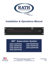
Note: For systems larger than 16 zones, connect the subsequent Supervisor Boards in series by connecting
any additional wire to the +Connector and to the RETURN Connector for feeding power to the next board in the
system. Wire up to 2 Supervisor Boards per transformer.
POWER IN
RETURN
+ 12VDC
12 VDC
POWER
SUPPLY
SUPERVISOR BOARD 1
POWER IN
RETURN
+ 12VDC
SUPERVISOR BOARD 2
Page 8
The factory default setting for the switches is in the DISABLE position. Set the
switches on all the monitored ports to the ENABLE position. Any port that has
equipment connected to it should be monitored.
Setting Switches
An external device, such as a re alarm panel, must be connected to the Supervisor
Board for external fault notication. To do this, attach the wiring from the external device
to the Normally Open (NO) or Normally Closed (NC) contacts of the notication relay.
Mounting
Mount the Supervisor Board to a wall using the provided swing arm bracket or to a 19” rack (not included).
Complete System Connections
1. Plug the power transformer into the power source (wall outlet or UPS).
2. Ensure the LEDs associated with the connected Supervisor ports are NOT illuminated and the GREEN status
light IS illuminated.
Note: When the unit powers on it will do a full check. This can take up to 90 seconds.
Once the check is complete with no errors, the green system status light will illuminate.
UPS
Setting Check Interval
1. Locate the “Test Interval” jumper on the back of the board.
2. The line check can be set to one of the following: 15 minutes,
6 hours, 12 hours, or 23 hours. Default is 15 minutes.
3. After determining desired time, move jumper so it vertically falls
under the correct time.
Alarm Wiring
Supervisor Board
Page 9
Testing
Once all equipment is connected and power is applied, wait 30 minutes before testing.
1. Disconnect the RJ11s from the front of the Supervisor Board.
2. The LED above the port will illuminate.
3. The system will do a full check before the relay will change state. The duration of this test is determined by the
timer jumper on the board plus 90 seconds (ex: If the timer jumper is set to 15 minutes, the relay will change after
15 minutes plus 90 seconds).
4. To reset, reconnect the RJ11 from the removed device. The red LED above the port will clear.
5. After all errored devices are reconnected, the green system status light should illuminate within 3 minutes.
Typical System Layout
Distribution Module
2500-UPS
Monitor
Fire
Control
Panel
Power Supply/UPS Backup
2400 Series
Call Box
2400 Series
Call Box
2400 Series
Call Box
Outside
Phone Line
Communication Failure
Relay Output
Power Failure
Relay Output
To 120vac
Addressable
Fire
Alarm
Module
22/24ga Single Pair
Provided
by RATH®
22/24ga Single Pair
Provided
Transformer
RATH® Supervisor
Command System
360 of Supervision
N56W24720 N. Corporate Circle • Sussex, WI 53089
800-451-1460 • www.rathcommunications.com 12/21
Twisted, Shielded
Wire Recommended
  • Page 1 1
  • Page 2 2
  • Page 3 3
  • Page 4 4
  • Page 5 5
  • Page 6 6
  • Page 7 7
  • Page 8 8
  • Page 9 9

ORATH 2500- SPRVSR Supervisor Board User manual

Type
User manual

ORATH 2500- SPRVSR Supervisor Board is a high-quality emergency communication device designed for use in various commercial and industrial applications. With its advanced capabilities, this board offers a reliable and efficient solution for monitoring and managing emergency phone systems. The ORATH 2500- SPRVSR Supervisor Board features a user-friendly interface, allowing for easy setup and configuration. It supports a range of functions, including zone monitoring, alarm activation, and integration with external systems.

Ask a question and I''ll find the answer in the document

Finding information in a document is now easier with AI