Page is loading ...

Betriebsanleitung (Original, Gül gkeit siehe letzte Seite)
ELMON relay 39-726 Sicherheitsschaltgerät
Seite 3-14
Manuel d’u lisa on (Validité voir la dernière page)
ELMON relay 39-726 Relais de sécurité
Opera ng Manual (see last page for validity)
ELMON relay 39-726 Safety Relay
Page 15-26
Page 27-38
EnglishFrançais Deutsch
Sicherheitsschaltgerät / Safety Relay / Relais de sécurité
ELMON relay 39-726

14
Sicherheitsschaltgerät
ELMON relay 39-726 ELMON relay 39-726ELMON relay 39-726

14 15
ELMON relay 39-726
Safety Relay
1. Contents
1. Contents . . . . . . . . . . . . . . . . . . . . . . . . . . . 15
2. General safety regulaons and protecve measures . . 16
3. General informaon and funconal descripon . . . . . 17
4. Proper use . . . . . . . . . . . . . . . . . . . . . . . . . . 18
5. Applicaon examples . . . . . . . . . . . . . . . . . . . . 18
5.1 Example of use for separated funcon . . . . . . . . . . . . . .18
5.2 Example of use for combined funcon . . . . . . . . . . . . . .18
6. Device overview. . . . . . . . . . . . . . . . . . . . . . . 19
6.1 Versions . . . . . . . . . . . . . . . . . . . . . . . . . . . . . . .19
6.2 Signal indicators . . . . . . . . . . . . . . . . . . . . . . . . . . . 19
6.3 Connecon terminals . . . . . . . . . . . . . . . . . . . . . . . . 19
6.4 DIP switches for seng the operang mode . . . . . . . . . . . 20
7. Operang modes . . . . . . . . . . . . . . . . . . . . . . 20
7.1 Automac reset . . . . . . . . . . . . . . . . . . . . . . . . . . . 20
7.2 Error lock - manual reset . . . . . . . . . . . . . . . . . . . . . . 20
7.3 Auxiliary output undelayed (RLU) . . . . . . . . . . . . . . . . . 20
7.4 Auxiliary output undelayed ashing (RLU) . . . . . . . . . . . .21
7.5 Auxiliary output delayed (RL) . . . . . . . . . . . . . . . . . . .21
8. Mechanical mounng. . . . . . . . . . . . . . . . . . . . 21
9. Electrical connecon . . . . . . . . . . . . . . . . . . . . 22
9.1 Connecng the supply voltage. . . . . . . . . . . . . . . . . . . 22
9.2 Connecng the sensor . . . . . . . . . . . . . . . . . . . . . . .22
9.3 Connecng mulple sensors per sensor circuit. . . . . . . . . . 22
9.4 Connecng the control circuits . . . . . . . . . . . . . . . . . .23
9.5 Special features of the safety-related semiconductor
outputs (OSSD) . . . . . . . . . . . . . . . . . . . . . . . . . . .23
9.6 Reset terminal. . . . . . . . . . . . . . . . . . . . . . . . . . . . 23
9.7 Auxiliary terminal . . . . . . . . . . . . . . . . . . . . . . . . . . 23
10. Commissioning and funconal test . . . . . . . . . . . . 23
11. Error diagnosis. . . . . . . . . . . . . . . . . . . . . . . . 24
12. Taking out of service and disposal . . . . . . . . . . . . . 24
13. Technical specicaons . . . . . . . . . . . . . . . . . . . 25
14. EC declaraon of conformity . . . . . . . . . . . . . . . . 26
We reserve the right to make technical and operaonally relevant changes to the
products and devices described in this documentaon at any me and without prior
noce.
English

16
English
For the design of the safety system to conform to engineer standards, the plant / machine
must be professionally inspected at appropriate intervals for proper funcon. The inspecon
must be documented in such a way as to be comprehensible at all mes.
The manufacturer assumes no liability in the event of non-observance or intenonal abuse.
2. General safety regulaons and protecve measures
• The manufacturer and users of the plant / machine on which the protecon is being used are responsible
for implemenng and following all applicable safety regulaons and rules.
• When used in conjuncon with the higher-order controller, the protecon guarantees funconal safety,
but not the safety of the enre plant / machine. The safety of the enre plant / machine must, therefore,
be assessed in accordance with machinery direcve 2006/42/EC or appropriate product norm before
using the device.
• The operang instrucons must always be available at the place of installaon of the protecon. They
must be read thoroughly and observed by all persons involved in the operaon, maintenance and servicing
of the protecon.
• The protecon must only be installed and commissioned by professionals familiar with these operang
instrucons and the applicable operaonal safety and accident prevenon regulaons. All of the instruc-
ons provided in these operang instrucons must be observed and followed. All electrical work must
only be performed by skilled electricians.
• All electrical work must only be performed by skilled electricians. All relevant electrical engineering and
Employer‘s Liability Insurance Associaon safety regulaons must be observed.
• During work on the switching unit, it is to be switched to zero potenal, checked to ensure that it is at
zero potenal and protected against being restarted.
•
The switching unit does not contain any components that require servicing by the user. Unauthorised con-
versions and repairs made to the switching unit will void all guarantees and the manufacturer’s liability.
• Auxiliary outputs must not perform any safety-related funcons. They are not one-fault safe and do not
undergo a test.
Safety Relay

16
17
ELMON relay 39-726
Safety Relay
English
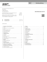
3. General informa on and func onal descrip on
The switching unit ELMON relay 39-726 is used for evalua ng safety contact mats and for safeguarding loca ons
where there is a risk of crushing and cu ng through the use of safety contact edges and safety bumpers.
Two separate ASO sensors can be connected to the switching unit. Monitoring of the standby current is made
possible by an integrated termina ng resistor in the sensors. According to the con gura on, the monitoring
state of the sensors is indicated by the outputs as combined func on or as separated func on.
Two safety outputs with non-isolated semiconductor outputs are available. If the idle state is detected at
the safety edges and if there are no faults present in the device, a voltage is output at the respec ve safety
outputs (corresponds to the supply voltage).
Two auxiliary outputs with poten al-free switching contacts are available. Actua on of the sensors triggers
a reac on by the auxiliary output according to the DIP switch con gura on. The auxiliary outputs must not
perform any safety func ons. They are not one-fault safe and do not undergo a test.
The switching unit is designed and type-approved in accordance with EN ISO 13849-1 „Safety-related parts
of control systems“ for category 3 Performance Level d. For Category 3 compliance, the safety outputs units
have a redundant and diverse design with two independent switching elements; of these, the semiconductor
switch‘s ability to turn o is constantly tested.
The monitoring state of the sensors and the auxiliary outputs, as well as the applied opera ng voltage are
indicated by LEDs.
If an error is present, all the safety outputs are not ac ve.
Reset
Mode
Manual
Reset
S11
+U2
R
ELMON relay 39-726
+U1
S12
Z1
Z2
SIG
CH1
X1
X2
SIG
CH2
Y1
Y2
Reset
Mode
AUX mode
OUT mode
Redundant
Logic
+24V
0V
14
31
32
24
41
42
OUT
CH1
OUT
AUX1
OUT
CH2
OUT
AUX2
+U1
+U2
R
S11
+U2
R
ELMON relay 39-726
+U1
S12
Z1
Z2
X1
X2
Y1
Y2
Reset
Mode
AUX mode
OUT mode
Redundant
Logic
+24V
0V
14
31
32
24
41
42
+U1
+U2
R

18
4. Proper use
The switching unit can only ful l its safety-related task if used properly.
The switching unit is intended to be used as protec on in combina on with safety contact mats, safety bumpers
and safety contact edges with 8.2 kΩ resistor for standby-current monitoring.
Any uses above and beyond these uses cons tute improper use. The manufacturer assumes no liability for
damages arising from improper use.
The device may only be used in special applica ons with the manufacturer’s express consent.
5. Applica on examples
Circuit diagram in zero-poten al state. Sensor not actuated.
The auxiliary relay output is used for visualising the switching state of the safety contact edge.
5.1 Example of use for separated func on
5.2 Example of use for combined func on
English
Safety Relay
24 32 4214S12S110V
+24V X1 X2 Y2 Y2 31 41
K1
K2
0V
+24V
8k2 8k2
S1 S2
K1
K2
Closed:
Opened:
Closed:
Opened:
Switch S2 open
Switch S2 closed
Switch S1 open
Switch S1 closed
ELMON relay 39-726
Separated func on
Opera on
mode:
auto reset
24
32
42
14
S12
S11
0V
+24V
X1
X2
Y2
Y2
31
41
K1
K2
0V
+24V
8k2
8k2
S1
S2
K1
K2
Closed:
Opened:
Closed:
Opened:
Switch S2 open
Switch S2 closed
Switch S1 open
Switch S1 closed
ELMON relay 39-726
Separated func on
Opera on
mode:
auto reset
24 32 4214S12S110V
+24V X1 X2 Y2 Y2 31 41
K1
K2
0V
+24V
8k2 8k2
S1 S2
K1
K2
Closed:
Opened:
Closed:
Opened:
Switch S1 and S2 open
Switch S1 or S2 closed
Switch S1 and S2 open
Switch S1 or S2 closed
ELMON relay 39-726
Shared func on
Opera on
mode:
auto reset
24
32
42
14
S12
S11
0V
+24V
X1
X2
Y2
Y2
31
41
K1
K2
0V
+24V
8k2
8k2
S1
S2
K1
K2
Closed:
Opened:
Closed:
Opened:
Switch S1 and S2 open
Switch S1 or S2 closed
Switch S1 and S2 open
Switch S1 or S2 closed
ELMON relay 39-726
Shared func on
Opera on
mode:
auto reset

18
19
ELMON relay 39-726
Safety Relay
English
6. Device overview
6.1 Versions
Housing, 22.5 mm wide, made of polyamide
for 35 mm DIN rail moun ng acc. to EN 60715.
6.2 Signal indicators
LED Power green
opera ng state (on)
error message (pulse output)
LED CH 1 red
sensor actuated (on)
sensor circuit interrupted ( ashes fast)
error lock ( ashes slowly)
LED CH 2 red
sensor actuated (on)
sensor circuit interrupted ( ashes fast)
error lock ( ashes slowly)
LED AUX 1 yellow
Auxiliary output switched
LED AUX 2 yellow
Auxiliary output switched
If no error is present, then LED Power shows the opera ng state (on). During the output of an error message,
the number of output pulses indicates the error:
Pulse Error message
1 Voltage supply outside of the valid value range
2 Tes ng sensor input faulty
3 Output control CH1 faulty
4 Output control CH2 faulty
5 Data transmission between microcontrollers faulty
6.3 Connec on terminals
+24V 0V Supply voltage 24 V DC, ± 10%
X1 X2 Connec on sensor 1
Y1 Y2 Connec on sensor 2
14 Relay switching contact 1
24 Relay switching contact 2
31 32 Switching contact auxiliary output 1
41 42 Switching contact auxiliary output 2
Z1 Z2 Connec on - manual reset/restart (bu on NO; op onal)
S11 S12 Coding inputs mode

20
6.4 DIP switches for seng the operang mode
Located on the right side of the housing are six DIP switches.
S1 «ON» safety output - combined funcon (OUT1, OUT2: CH1 + CH2)
«OFF» safety output - separated funcon (OUT1: CH1; OUT2: CH2) (factory seng)
S2 «ON» auxiliary output - combined funcon (AUX1, AUX2: CH1 + CH2)
«OFF» auxiliary output - separated funcon (AUX1: CH1; AUX2: CH2) (factory seng)
S3 «ON» Mode auxiliary output AUX1: RL
«OFF» Mode auxiliary output AUX1: RLU (factory seng)
S4 «ON» Mode auxiliary output AUX2: RL
«OFF» Mode auxiliary output AUX2: RLU (factory seng)
S5 «ON» auxiliary output AUX1 and AUX2 ash on RLU
«OFF» auxiliary output AUX1 and AUX2 do not ash on RLU (factory seng)
S6 «ON» Auxiliary output AUX1 and AUX2 are acve in the idle state on RLU
«OFF» Auxiliary output AUX1 and AUX2 are inacve in the idle state on RLU (factory seng)
7. Operang modes
7.1 Automac reset
(S11 S12 bridged)
Following reccaon of a fault in a sensor circuit or aer a power failure, the switching unit automacally
re-enables the output.
7.2 Error lock - manual rese
(S11 S12 not connected)
Following reccaon of a fault in a sensor circuit or aer a power failure, the switching unit does not re-
lease the output(s) unl contacts Z1 and Z2, 500 ms aer the eliminaon of the disrupon, are closed with
a buon. An automac restart is thereby rendered impossible. Permanent bridging of contacts Z1 Z2 does
not result in an automac reset.
7.3 Auxiliary output undelayed (RLU)
(S3 = «OFF» or S4 = «OFF»; S5 = «OFF»)
In this operang mode, the corresponding auxiliary output is acvated without delay if any error is signalled
on the respecve channel. The auxiliary output can be toggled between normally closed contact and normal-
ly open contact with S6 („ON“ = normally closed contact), whereby the output is always inacve while the
switching unit is in a power-free state.
English
Output
Aux. Relay
Safety output (symbolic)
Auxiliary output (symbolic)
Safety Relay

20 21
7.4 Auxiliary output undelayed ashing (RLU)
(S3 = «OFF» or S4 = «OFF»; S5 = «ON»)
With this DIP switch, ashing of the auxiliary output AUX1 and AUX2 can be acvated on mode RLU.
1,5 s 1,5 s
7.5 Auxiliary output delayed (RL)
(S3 = «ON» or S4 = «ON»)
In this operang mode, the respecve auxiliary output is acvated with a delay of approx. 0.5 second and
then remains acve for max. 3 seconds if an error is signalled.
0,5 s 3 s
8. Mechanical mounng
The switching unit must be professionally mounted:
- In a dust- and moisture-protected switching cabinet or housing.
- Installaon in a Polluon Degree 2 environment.
- With a protecon class of at least IP54.
- On a 35 mm DIN mounng rail acc. to EN 50 022.
The switching unit must not be mounted in the immediate vicinity of strong sources of heat.
The switching unit may be mounted in any orientaon.
ELMON relay 39-726
Safety Relay
English
Output
Aux. Relay
Safety output (symbolic)
Auxiliary output (symbolic)
Output
Aux. Relay
Safety output (symbolic)
Auxiliary output (symbolic)

22
9. Electrical connecon
The switching unit facilitates operaon with a supply voltage of 24 V DC ± 10%.
All applied voltages must comply with the requirements for Safety Low Voltage (SELV). The outputs are not
galvanically isolated from the supply voltage.
- Connecng to the wrong terminals can destroy the switching unit.
-
Cables installed outdoors or outside of the switching cabinet must be protected appropriately.
The signal cable must not be placed parallel to the motor cable or other power cables.
9.1 Connecng the supply voltage
Connect 24 V DC supply voltage to terminals +24 V 0 V.
The supply voltage used must comply with the requirements for safety low voltage (SELV).
The supply line to the switching unit must be protected with an appropriate fuse.
9.2 Connecng the sensor
Connect sensor to terminals X1 X2 or Y1 Y2.
If a channel is not used, it must be connected to an 8.2 kΩ resistor.
9.3 Connecng mulple sensors per sensor circuit
ASO-sensors must not be connected in parallel.
One or more sensors can be connected to sensor input. For this purpose, the individual sensors are connected
in series according to gure 1.
Safety edges SENTIR edge:
Up to ve SENTIR edge may be connected in series. The maximum total length o the SENTIR edge shall not
exceed 100 m.
The length of one SENTIR edge may be up to 25 m.
The total cable length o the in series connected SENTIR edge must not exceed 25 m.
Safety bumper SENTIR bumper:
Up to ve SENTIR bumper may be connected in series. The maximum total length o the SENTIR bumper
shall not exceed 15 m.
The length of one SENTIR bumper may be up to 3 m.
The total cable length o the in series connected SENTIR bumper must not exceed 25 m.
Safety contact mat SENTIR mat:
Up to ten SENTIR mat may be connected in series. The maximum total area shall not exceed 10 m
2
.
The maximum size of an SENTIR mat is 1350 x 2350 mm.
The total cable length o the in series connected SENTIR mat must not exceed 25 m.
Before connecng the sensors that are connected in series, it is recommended that the resistance value of
the arrangement is to be measured. The resistance must be 8.2 kΩ ± 500 Ω when the sensor is inacve and
must not exceed 500 Ω when it is acve.
Figure 1: Wiring of mulple sensors; in this example: safety contact edge
Sensor „n“
Sensor 2
Sensor 1
X1
X2
English
Safety Relay
2
222

22 23
ELMON relay 39-726
Safety Relay
English
9.4 Connecng the control circuits
Connect the control circuit that is to be monitored to terminals 14 or 24 respecvely. The cables are to be laid
so that it is impossible to bridge the safety contacts, e.g. by a short circuit between the two connecon wires.
The connecon for the control circuits is permied only for switching low voltages. The control circuits are
dependent on the rated current to protect with an appropriate fuse or the rated current to the control circuits
must be limited by other measures to the maximum value.
9.5 Special features of the safety-related semiconductor outputs (OSSD)
The output‘s ability to turn o is also constantly tested while the safety outputs are acvated. For this
purpose, the semiconductor output switch is switched o several mes per second for less than 1 ms and
the response at the output observed.
These interrupons must not be evaluated by the higher-order controller as safety requests.
If the voltage does not return to 0 V, the device is permanently deacvated and can only be reset by switching
o and on the voltage supply.
This permanent deacvaon also occurs if, depending on the type of acvaon, the voltage cannot break
down (e.g. by means of capacive elements).
A primary controller should only evaluate the states of the output signal if the level is sustained for 5 ms. This
prevents pulses generated during a self-test while in the switched-on state and the tesng of the switch-on
procedure from erroneously being processed as control informaon.
9.6 Reset terminal
For automac reset / restart terminals S11 S12 are to be bridged (factory seng: manual reset, S11 S12
unbridged) and reset push-buon is to be connected to terminals Z1 Z2.
9.7 Auxiliary terminal
The auxiliary terminals serve only as auxiliary terminals (signalling, display, etc.) and must not perform any
safety funcons.
10. Commissioning and funconal test
The plant / machine must be tested for proper funcon aer all of the electrical connecons have been
established and the supply voltage has been turned on.
Upon successful commissioning, a voltage is output at the safety outputs (corresponds to the supply voltage).
Actuaon of the sensor causes a reacon by the safety outputs and by the auxiliary outputs according to the
DIP switch conguraon.
The safety system must be professionally inspected at appropriate intervals. The inspecon must be
documented in such a way as to be comprehensible at all mes. The requirements of the plant/machine
manufacturer are to be taken into account and followed.

24
LED Error Error correcon
No LED
illuminates
The supply voltage is missing,
too low or has been connected
incorrectly
Check connecons and supply voltage:
- 24 V DC at terminals +24 V 0 V
- Correct polarity? +24 V at terminal +24 V
Tolerance range: ±10%
green LED
ashes cyclically
(pulse output)
Internal error is indicated by the
number of pulses.
See -> Signal indicators
red LED
is illuminated
(CH1 or CH2)
The corresponding safety sensor
detected as having been actuated.
- Check the connecons of the corresponding
sensors (squeezed or brile supply lines, etc.)
- Check sensors *
red LED
ashes fast
(CH1 or CH2)
sensor circuit interrupted , Sensor(s)
not connected,
connected incorrectly or faulty.
- Check the connecons of the corresponding
sensors (squeezed or brile supply lines, etc.)
- Check sensors *
red LED
ashes slowly
(CH1 or CH2)
error lock Perform manual reset
11. Error diagnosis
Only the green LED may illuminate if the supply voltage has been correctly connected. If one of the red LEDs
illuminate, there is an error in the system which can be pinpointed with the aid of the LED.
The yellow LEDs for the auxiliary outputs illuminate according to the DIP-switch sengs.
If the error is not in the wiring, the funcon of the electronics can be tested by connecng an 8.2 kΩ resistor
to the sensor input on the switching unit. If the electronics work perfectly aer performing the test, the
sensor must be checked using an ohmmeter. To do this, the connecon of the sensor to the switching unit
must be disconnected and connected to an ohmmeter. The resistance must be 8.2 kΩ ±500 Ω when the
sensor is inacve and must not exceed 500 Ω when the sensor is acve.
*
12. Taking out of service and disposal
The products manufactured by ASO are intended solely for commercial use (B2B). At the end of use, the
products are to be disposed of according to all local, regional and naonal regulaons. Products can also be
returned to ASO, which will then dispose of them properly.
English
Safety Relay

24
25
ELMON relay 39-726
Safety Relay
English
13. Technical speci ca ons
Supply voltage
Extra Low voltage: U
E
24 V DC ±10 % (SELV)
Power consump on P
E_max
< 1 W (24 V DC)
Termina ng resistor – sensor
Nominal value R
nom
= 8,2 kΩ
Upper switching point R
AO
> 12,0 kΩ
Lower switching point R
AU
< 5,0 kΩ
Safety outputs (OSSD)
max. switching voltage U
O_max
26,4 V DC
max. switching current I
O_max
2 A DC (output per)
Electrical life- me >10
5
actua ons
U liza on category DC-13 (30 V; 2 A; 1000000 Op.)
Switching mes - safety output
Switching o delay <= 4ms
(Response me)
Switching on delay 500ms (Power on 700ms)
Auxiliary output
Max. switching voltage 50 V AC/DC
Max. switching current 2 A AC/DC
Mechanical life- me > 5 x 10
6
actua ons
Switching mes - auxillary output
RL-func on:
Switching on delay 0,5 s ±0,2 s
Switching o delay 3 s ±1 s
With the RLU func on, the auxiliary relay switches in synch with sensor actua on.
Enclosure
Polyamide PA 6.6
Self-ex nguishing acc. to UL 94-V2
Dimensions (HxWxD) 99 x 22,5 x 114 mm
Degree of protec on IP20
Pollu on Degree 2
Weight approx. 160 g
Temperature range -20 °C to +55 °C
Connec on cable cross-sec on
single- or ne-stranded cable 0,75-1,5 mm2
Temperature class copper conductors 60/75°C
Cer ca ons EN ISO 13849-1:2008 category 3 PL e
(MTTFd 182 years, DC 94,67 %)
EN 62061:2013 SILCL 3
(PFHd 1,13E-08 1/h = PFHd1+ PHFd2)
Electronics MTTFd 351 years, DC 99 %
PFHd1 = 3,79E-09 1/h
Electromechanics B10d 2000000
MTTFd 380 years, DC 90% (Nop 52560)
PFHd2 = 7,51E-09 1/h
114
22,5
99

26
Safety Relay
ELMON relay 39-726 ELMON relay 39-726ELMON relay 39-726

38
Relais de sécurité
Français
ELMON relay 39-726 ELMON relay 39-726ELMON relay 39-726

40
11.DB.16.001 Betriebsanleitung Rev 06
Technische Änderungen vorbehalten.
Für Irrtümer und Druckfehler kann keine Haung übernommen werden.
Diese Betriebsanleitung ist für folgende Versionsstände gülg: V 1.0 bis V 3.4
11.DB.16.001 Operang Manual Rev 06
Subject to technical modicaons.
No liability can be assumed for errors or misprints.
This operang manual is valid for the following versions: V 1.0 to V 3.4
Deutsch
English
11.DB.16.001 Manuel d’ulisaon Rév 06
Sous réserve de modicaons techniques.
Nous déclinons toute responsabilité en cas d'erreurs et de fautes d'impression.
Ce mode d’emploi n’est valable que pour les versions suivantes: V 1.0 à V 3.4
Français
Sicherheitsschaltgerät / Safety Relay / Relais de sécurité
Antriebs- und Steuerungstechnik
Hansastraße 52 • D-59557 Lippstadt
Tel.: +49 2941 9793-0 • Fax: +49 2941 9793-299
www.asosafety.de • e-mail: aso-eu@asosafety.com
/