Page is loading ...

1
2
3
4
5
6
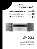
Fig. 1
ECONOMY SMART
DC 24 V / RELAY
Elektronischer Schutzschalter
Electronic Circuit Breaker
Disjoncteur électronique
BLOCK Transformatoren-Elektronik GmbH
Max-Planck-Straße 36-46 . 27283 Verden, Germany
info@block.eu . block.eu
#005-0220 / Rev. a 08.10.2021
Funktionsschaltbild
Function diagram
Schéma fonctionnel
Der elektronische Schutzschalter teilt den Laststrom auf mehrere 24-V-Abzweige auf
und überwacht sie zuverlässig auf Überlast und Kurzschluss. Kurzfristige Strom-
spitzen, z.B. durch einen hohen Einschaltstrom, lässt die Elektronik zu, Abzweige mit
längerer Überlast schaltet sie stromlos.
Der Auslösestrom eines jeden Ausgangs kann individuell in 6 Stufen einge-
stellt werden. Die Ausgänge werden zeitversetzt und lastabhängig eingeschaltet,
um Spitzeneinschaltströme zu verringern. Bei Überschreitung des Nennstromes
wird der Ausgang nach einer definierten Auslösezeit automatisch abgeschaltet und
kann nach einer kurzen Wartezeit (thermische Entspannung) mittels Taster oder per
Signalkontakt wieder eingeschaltet werden. Der Taster dient ebenfalls zum manuellen
Abschalten des jeweiligen Ausgangs. Über eine mehrfarbige LED wird der Status des
jeweiligen Ausgangs angezeigt.
Funktionsbeschreibung
Bitte lesen Sie diese Warnungen und Sicherhinweise sorgfältig durch, bevor Sie das
Gerät in Betrieb nehmen. Das Gerät darf nur durch fachkundiges und qualifiziertes
Personal installiert werden. Bei Funktionsstörungen oder Beschädigungen schal-
ten Sie sofort die Versorgungsspannung ab und senden das Gerät zur Überprüfung
ins Werk. Das Gerät beinhaltet keine Servicebauteile. Bei Auslösen einer internen
Sicherung liegt höchstwahrscheinlich ein interner Defekt am Gerät vor. Die angege-
benen Daten dienen allein der Produktbeschreibung und sind nicht als zugesicherte
Eigenschaften im Rechtssinne aufzufassen.
Bestimmungsgemäßer Gebrauch
Dieses Gerät ist für den Einbau in ein Gehäuse konzipiert und zur Verwendung für allge-
meine elektronische Geräte, wie z.B. Industriesteuerungen, Bürogeräte, Kommunikati-
onsgeräte oder Messgeräte geeignet. Benutzen Sie dieses Gerät nicht in Steuerungs-
anlagen von Flugzeugen, Zügen oder nuklearen Einrichtungen, in denen eine Funktions-
störung zu schweren Verletzungen führen oder Lebensgefahr bedeuten kann.
Installation
Die Installation ist entsprechend den örtlichen Gegebenheiten, einschlägigen Vor-
schriften, nationalen Unfallverhütungsvorschriften und den anerkannten Regeln der
Technik durchzuführen. Dieses elektrische Betriebsmittel ist eine Komponente, die
zum Einbau in elektrische Anlagen oder Maschinen bestimmt ist und erfüllt die Anfor-
derungen der Niederspannungsrichtlinie (2014/35/EU). Der geforderte Mindestab-
stand zu benachbarten Teilen ist einzuhalten, um die Kühlung nicht zu behindern!
Vor Inbetriebnahme lesen
The electronic circuit breaker distributes and monitors the load current over several
current circuits. Overloads and short circuits on an output are reliably recognized. The
electronics permit brief current peaks and switch longer overloads off.
The rated current for each output can be individually set in 6 steps. The outputs
are time-delay and load-depend activated to avoid overload current. If the rated
current is exceeded for a certain time, the output will be switched off automatically
and can be switched on after a waiting time (thermal relaxation) using the pushbutton
or the remote signal-input S1. The pushbutton can also be used to switch the output
manually. The state of each output is also indicated with a multi-colored LED.
Product Description
Le disjoncteur électronique distribue et supervise le courant sur plusieurs circuits
24VDC, détectant de manière fiable les surcharges et courts-circuits. Le disjoncteur
autorise de brefs pics d‘intensité, par exemple un courant d‘appel élevé, et déclenche
une voie ayant une surcharge plus longue.
Le courant de déclenchement de chacune des sorties peut être paramétré
individuellement, 6 seuils sont disponibles. Les voies sont enclenchées de manière
séquentielle et dépendante de la charge, de manière à réduire le courant d‘appel. Si
le seuil de déclenchement est dépassé pendant un certain temps, la voie de sortie
se déclenche. La voie de sortie peut être réenclenchée après un court délai (détente
thermique) en utilisant le bouton en façade ou à distance par l‘entrée S1. Le bouton en
façade peut aussi permettre un déclenchement manuel de chaque voie. Le statut de
chacune des voies est indiqué en façade par un voyant multicolore.
Fonctionnement général
Before operating this unit please read the manual thoroughly. This device may only be
installed and put into operation by qualified personnel. If damage or malfunction should
occur during operation, immediately turn power off and send unit to the factory for
inspection. The unit does not contain serviceable parts. The tripping of an internal fuse
is caused by an internal defect.
The information presented in this document is believed to be accurate and reliable and
may change without notice.
Intendend Use
This device is designed for installation in an enclosure and is intended for general use
such as in industrial control, office, communication, and instrumentation equipment.
Do not use this device in aircraft, trains and nuclear equipment where malfunction may
cause severe personal injury or threaten human life
Installation
Installation must be carried out according to the prevailing local conditions and safety
regulations, national accident prevention regulations and the generally accepted rules
of technology. This equipment is a component designed for installation into electrical
systems and machines, and fulfills the requirements of the low voltage guidelines
(2014/35/EU). The required minimum spacing to neighboring components must be
observed to guarantee the required cooling!
Read this first
Veuillez lire soigneusement ces avertissements et consignes de sécurité avant de
met tre l’appareil en service. L’appareil ne doit être installé que par du personnel
compétent et qualifié. En cas de dysfonctionnement, couper immédiatement la tension
d’alimentation et retourner l’appareil à l’usine pour vérification. L’appareil ne contient
pas de pièces échangeables. En cas de déclenchement d’un fusible interne, l’appareil
présente vraisemblablement un défaut. Les données indiquées sont à but descriptif.
Elles ne doivent pas être interprétées comme des caractéristiques assurées au sens
juridique du terme.
Usage conforme
Cet appareil est conçu pour être installé en armoire et convient à une utilisation sur
des installations électriques générales telles que des commandes industrielles, des
appareils de bureau, de communication ou de mesure. Ne pas utiliser cet appareil à
bord des commandes d’avions, de trains, ou installations nucléaires, dans lesquelles un
dysfonctionnement peut entrainer des blessures graves ou signifier un risque mortel
Installation
L’installation doit être réalisée conformément aux recommandations locales, aux
directives nationales relatives à la prévention des accidents ainsi que les normes
techniques reconnues. Cet équipement est un composant destiné à un montage
sur des systèmes et des machines électriques. Il est conforme aux conditions de la
Directive Basse tension (2014/35/EU). La distance minimale requise avec les modules
avoisinants doit être respectée afin de ne pas entraver le refroidissement .
A lire avant la mise en service
Bedienelemente
Fig. 1
1
2
3
4
5
Plombierbare Abdeckung der Stromwahlschalter
Eingang (+24 V und 0 V) Der Anschluss 0V dient nur der Eigenversorgung des
Schutzschalters.
Ausgänge zum Anschluss der Verbraucherkreise. Die 0 V der Verbraucher sind
über getrennte Leitungen direkt zur Stromversorgung zu führen.
Taster An/Aus/Reset mit integrierter LED
Signal- und Steuerkontakte S1/13/14
S1 = Reset-Eingang (Wiedereinschalten von ausgelösten Ausgängen)
13/14 = potentialfreier Meldekontakt (Schließerkontakt geöffnet,
wenn mindestens ein Ausgang ausgelöst oder manuell ausgeschaltet ist)
1
2
3
4
5
Sealed cover of the current-selector-switches
DC input (+24 V and 0 V) The 0 V connection of the device merely serves to supply
the internal electronic circuits.
Outputs for connecting the load circuits. The 0 V of the loads must be supplied
directly to the power supply by means of separate lines.
Pushbuttons On/Of f/Reset with integrated LED
Signal- and control contacts S1/13/14
S1 = Reset-input (reset of tripped outputs)
13/14 = potential-free signal output (opened, if minimum one output is tripped
or switched off manually)
User elements
Fig. 1
1
2
3
4
5
Capot de protection des sélecteurs
Entrée DC (+24 V et 0 V).
La connexion du 0 V est utilisée uniquement pour l‘alimentation du disjoncteur
Sorties pour le raccordement des charges. Le 0 V des charges doit être raccordé
directement à l‘alimentation électrique par des câbles séparés.
Bouton marche/ arrêt / réinitialisation avec LED intégrée
Contacts de signal et de contrôle S1/13/14
S1 = Entrée réinitialisation (réinitialisation des sorties déclenchées)
13/14 = Contact de signalisation sans potentiel (ouvert si au moins une sortie
est déclenchée ou désactivée manuellement)
Eléments de commande
Fig. 1
Betriebszustände,
Signalisierung, Reaktionen
Operating states,
Signaling, Reactions
Etats de fonctionnement,
signalisation, réactions
1) Nach Abschluss der Modulinitialisierung werden die Ausgänge lastabhängig eingeschaltet.
2) Der Ausgang wird gemäß Auslösekennlinie automatisch abgeschaltet. Bei Abschaltung Übergang nach
Betriebszustand Z4.
3) Der Zustand jedes Ausgangs wird beim Ausschalten des Gerätes gespeichert.
4) Nach einer Wartezeit (thermische Entspannung) Übergang nach Betriebszustand Z5. Beim Ausschalten
des Gerätes wird die restliche Wartezeit gespeichert und beim Wiedereinschalten abgewartet. Dadurch
wird auch bei sofortigem Wiedereinschalten des Gerätes eine Überlastung der Schaltelemente zuverlässig
verhindert.
5) Der betroffene Ausgang kann durch zweimaligen Tastendruck oder über einen Impuls (> 0,5s) an
Signaleingang S1 wiedereingeschaltet werden, Übergang nach Betriebszustand Z1.
1) After the initialization of the device the outputs are switched on (load dependent).
2) The output is automatically deactivated in accordance with tripping-curves-characteristics.
3) The state is saved at power-off of all outputs.
4) After a specific time interval (Thermal relief) change to operational condition Z5. If the unit is switched off
the remaining time is saved and will resume with the next switch on. This reliably prevents overloading if the
unit is immediately switched back on.
5) The affected output can be reset by pressing the push button twice or through an impulse (>0,5s) on signal
input S1. Change to operational condition Z1.
1) Une fois le module initialisé, les sorties seront activées dépendamment de la charge.
2) La sortie est désactivée automatiquement conformément à la caractéristique de déclenchement
3) L’ét at de f onctionnemen t de chaque sortie est enregist ré à la coupure de l’appareil.
4) Après un délai d’attente (détente thermique), la sortie peut être réactivée. Le temps d’attente restant est
enregistré lor s de la coupure de l’appareil e t son expiration se fera au r edémarrage.
5) La sortie concernée peut être réinitialisée en pressant 2 X sur le bouton ou via une impulsion (>0.5s) sur la
l‘entrée de commande S1 , passage à l‘état Z1.
Betriebszustand /
Beschreibung Ausgang LED Meldekontakt 13/14
(Summensignal)
Taster wird gedrückt
=> Übergang nach...
Steuereingang S1
=> Übergang nach ...
Z 0 Modulinitialisierung 1) aus aus offen --- ---
Z 1 Ausgang eingeschaltet,
Funktion OK
ein grün geschlossen Z 3 ---
Z 2 Ausgangsstrom >
Nennstrom 2)
ein grün
blinkend
geschlossen Z 3 ---
Z 3 Ausgang ist manuell
abgeschaltet 3)
aus rot offen Z 1 ---
Z 4
Ausgang ist aufgrund
eines Überstroms ab-
geschaltet, thermische
Entspannung aktiv 4)
aus rot
blinkend
offen --- ---
Z 5
Ausgang ist aufgrund
eines Überstroms
abgeschaltet, thermi-
sche Entspannung ist
beendet 5)
aus orange
blinkend
offen Z 3 Z 1 (mittels Impuls > 0,5s)
Z 6 Gerätefehler (defekte
Sicherung detektiert)
aus rot schnell
blinkend
offen Z 6 ---
State / Description Output LED Signal output 13/14
(Group alarm)
Pushbutton pressed
=> go to...
Signal input S1
=> go to...
Z 0 Initialization 1) off off opened --- ---
Z 1 Output on, function OK on green closed Z 3 ---
Z 2 Output current > rated
current 2)
on green
flashing
closed Z 3 ---
Z 3 Output was switched off
manually 3)
off red opened Z 1 ---
Z 4
Output was switched
off automatically (over
current), thermal
relaxation active 4)
off red
flashing
opened --- ---
Z 5
Output was switched
off automatically (over
current), thermal
relaxation finished 5)
off orange
flashing
opened Z 3 Z 1 (through impulse > 0,5 s)
Z 6 Output malfunction
(internal fuse blown)
off red flasing
fast
opened Z 6 ---
Etat de fonctionnement /
Description Sortie LED
Contact de signalisa-
tion 13/14
(Signal collectif)
Bouton est actionné
=> aller à...
Entrée de commande S1
=> aller à...
Z 0 Initialisation de module 1) arrêt arrêt Ouvert --- ---
Z 1 Sortie activée, Fonction OK marche vert Fermé Z 3 ---
Z 2 Courant de sortie > Courant
nominal 2)
arrêt clignote
vert
Fermé Z 3 ---
Z 3 La sortie est déactivée
manuellement 3)
arrêt rouge Ouvert Z 1 ---
Z 4
La sortie est désactivée en raison
d‘un courant de surcharge,
détente thermique active 4)
arrêt clignote
rouge
Ouvert --- ---
Z 5
La sortie es t désactivée en raison
d‘un courant de surcharge,
la détente thermique est terminée 5)
arrêt clignote-
orange
Ouvert Z 3 Z 1 (par impulsion
>0,5 s)
Z 6
Erreur de l‘appareil (fusible interne
défectueux détecté)
arrêt clignote
rapidement
rouge
Ouvert Z 6 ---
CONTROL UNIT
LOAD 1 LOAD 8
S1
OUT 1(+)
IN 4 (–) IN 2 (+)IN 3 (–) IN 1 (+)
OUT 8(+)
+
13
–
14
AC
DC
DC 24 V
LOAD 2
OUT 2(+)
...
français / english / deutsch
deutsch english français

Sicherungskennlinie
Tripping characteristic
Caractéristique du disjoncteur
Fig. 4a
I
II
III
IV
V
Fig. 4b
II
I
deutsch english français
Der elektronische Schutzschalter ist
mit drei Signal- bzw. Steuerkontakten
ausgestattet.
Über den Steuereingang S1 ist der
Reset von allen ausgelösten Ausgängen
möglich, sofern für mindestens 0,5
Sekunden 24 V an den Steuereingang S1
eingespeist wird.
Der potentialfreie Meldekontakt 13/14
signalisiert das Auslösen mindestens
eines Kanals aufgrund eines Überstroms
sowie das Abschalten mindestens eines
Kanals.
The electronic circuit breaker is equipped
with three signal contacts.
The signal input S1 provides the
possibility to reset each tripped outputs
by placing a defined signal at the input.
The potential-free contact 13/14 works
as group alarm message. If minimum one
output is tripped or minimum one output
is switched off manually, the group alarm
contact is opened.
Le disjoncteur électronique dispose de
trois contacts de signal et de commande.
L‘entrée de commande S1 permet la
réinitialisation de toutes les sorties
déclenchées dès lors qu‘une tension de
24V est appliquée pendant au moins 0,5
seconde sur l‘entrée S1.
Le contact de signalisation sans potentiel
13/14 signale le déclenchement
d‘au moins un canal en raison
d‘une surintensité de courant et la
désactivation manuelle d‘au moins un
canal.
Signalisierungs- und Steuer-
kontakte S1/13/14
Signal- and control
contacts S1/13/14
Contacts de signal et de
contrôle S1/13/14 T
Hinweis:
Eine detaillierte Beschreibung finden Sie im
Handbuch des Schutzschalters, das auf der
Produktseite unter www.block.eu kostenlos zum
Download bereitsteht.
Notice:
You can download the complete manual with
detailed description from our product site under
www.block.eu.
Indication:
Vous trouverez une description détaillée dans
le manuel du disjonc teur de protec tion que vous
pouvez télécharger gratuitement sur la page
produit à l‘adresse www.block.eu
Mounting
Fig. 4a
AUF TRAGSCHIENE AUFRASTEN
I) Gerätevorderseite leicht nach oben
drehen
II) Auf Hutschiene aufsetzen
III) Bis zum Anschlag nach unten
schieben
IV) Unten gegen die Befestigungsebene
drücken (klick)
V) Leicht am Gerät rütteln, um Verrie-
gelung zu prüfen
Fig. 4b
DEMONTAGE VON TRAGSCHIENE
I) Verriegelungslasche mit Schrauben-
dreher nach unten ziehen und öffnen.
II) Gerät aus Tragschiene aushängen.
Montage
Fig. 4a
SNAP ON SUPPORT RAIL
I) Tilt the unit slightly rearwards
II) Fit the unit over top hat rail
III) Slide it downward until it hits the stop
IV) Press against the bottom front side
for locking (click)
V) Shake the unit slightly to check the
locking action
Fig. 4b
REMOVAL FROM DIN RAIL
I) Locking tab with a screwdriver and
pull down to open.
II) Unhook the device from DIN rail.
Montage
Fig. 4a
POUR FIXER LE MODULE SUR LE RAIL
I) Pencher légèrement le module vers
l‘arrière
II) Placer le module sur le bord supérieur
du rail.
III) Encliqueter le module vers le bas
jusqu‘à l‘arrêt.
IV) Afin de verrouiller le module, pousser
sur la partie inférieure (clic)
V) Vérifier l‘enclenchement en secouant
légerement le module.
Fig. 4b
DEMONTAGE DU RAIL
I) Tirer le dispositif de verrouillage à
l‘aide d‘un tournevis vers le bas
pour ouvrir.
I I ) D é c r o c h e r l ‘ a p p a r e i l d u r a i l D I N .
110
10
100
1000
10000
100000
100
Auslösezeit (ms)
Tripping time (ms)
Temps de déclenchement (ms)
ü
Ausgangsstrom (A)
Output current (A)
Courant de sortie (A)
ü
2 A 3 A 4 A 6 A
8 A
10 A
PM-0724-400-2 PC-0724-800-2
Eingangsdaten Input data Entrée
Output: 2 - 10 A / channel
Eingangsnennspannung Nominal input voltage
Tension nominale d‘entr ée
DC 24 V
Eingangsspannungsbereich Input voltage range
Plage de tension d‘entrée
18 - 30 Vdc
Maximale Restwelligkeit/Rippel der
speisenden Eingangsspannung
Maximal residual ripple of supplied
input voltage
Ondulation résiduelle maximale/
ondulation de la tension d‘entrée
d‘alimentation
3%
Erforderliche Eingangsspannung zum
Einschalten der Ausgänge
Required input voltage for turning on
of outputs
Tension d‘entrée requise pour
l‘activation des sorties
20 V
Max. Dauerstrom des Moduls Max. total input current Courant permanent max. du module
40 A 70 A
Max. Dauerstrom pro Klemmenpol Max. input current for each pole of
terminal
Courant permanent max. par pôle
de borne 40 A
Überspannungsschutz
Suppressordiode
Over voltage protection
Suppressor diode
Protection contre les surtensions
Diode transil 33 V
Ruhestrom im Leerlauf @ 24 V Stand-by current @ 24 V Courant de repos à vide @ 24V 35 mA 55 mA
Ver lust leis tung im Leerlauf @ 24 V Power losses in stand-by mode
@ 24 V
Pertes en puissance à vide @ 24V 0,84 W 1,32 W
Anschlüsse Eingang Terminals input Raccordement entrée Push-In, max. 6 mm² (2 x „+“) see Tab. 1
Push-In, max. 2,5 mm² (2 x „-“) see Tab. 1
Ausgangsdaten Output data Sortie
Ausgangsnennspannung Nominal output voltage Tension nominale de sortie DC 24 V
Ausgangsnennströme
einstellbar
Nominal output current
adjustable
Courants nominaux réglable des
sorties 4 x (2, 3, 4, 6, 8, 10 A)
8 x (2, 3, 4, 6, 8, 10 A)
Maximaler Spannungsabfall zwischen
Ein- und Ausgang
Maximum voltage drop between input
and output
Chute de tension maximale entre
entrée et sortie 200 mV @ 4 x 10 A
200 mV @ 8 x 10 A
Modulinitialisierungszeit Initialization time Temps d‘initialisation de module 250 ms
Zuschaltverzögerung der Kanäle
lastabhängig
Turn-on delay of outputs
load dependent
Retard d‘activation des canaux
selon la charge min. 50 ms / max. 5 s
Wartezeit nach Abschaltung eines
Ausgangs (Thermische Entspannung)
Kurzschluss (A) ... Überlast (B)
Waiting periode after switch-off of an
output (thermal relaxation)
short circuit (A) ... overload (B)
Temps d‘attente après mise hors ser-
vice d‘une sortie (détente thermique)
court-circuit (A) ... surcharge (B)
500 ms (A) … 20 s (B)
Maximale Verlustleistung Maximum power losses Pertes en puissance maximales 10 W @ 4 x 10 A
20 W @ 8 x 10 A
Wirkungsgrad Efficiency Rendement 99%
Maximale Lastkapazität pro Ausgang Maximum turn-on capacity for each
output
Charge capacitive maximale par
sortie min. 63 mF @ 24 Vdc / 2,5 mm² / 2,5 m
Integrierte Ausgangssicherungen
pro Ausgang
Internal out put fuse for each out pu t Fusibles de sor tie int er ne par sor tie 15 A
Rückspeisefestigkeit Resistance to reverse feed max. Tension de retour max. 35 V
Parallelschaltung von Ausgängen Parallel use of outputs Montage en parallèle de sorties -
Serienschaltung von Ausgängen Serial use of outputs Montage en série de sorties -
Anschlüsse Ausgänge Terminals outputs Raccordement sorties Push-In, max 2,5 mm² (4 x „+“) see Tab. 1
Push-In, max 2,5 mm² (8x
„+“)
see Tab. 1
Signalisierung Signaling Signalisation
Statusanzeige (pro Ausgang)
LED (rot, grün, orange)
Status display (for each output)
LED (red, green, orange)
Indication du st atut (par sor tie)
LED (rouge, verte, orange)
Signaleingang S1
(Reset)
Signal input S1
(Reset)
Entrée de commande S1
(Réinitialisation)
DC 24 V
Level high = min. 15 V, max . 30 V
Level low = min. 0 V, max. 5 V
Potentialfreier Signalausgang 13/14
(Sammelmeldeausgang)
Potential-free signal output 13/14
(group alarm)
Sortie de signal sans potentiel 13/14
(message collectif)
13/14 = closed: Status OK
13/14= opened: minimum one channel is tripped or switched off
max. 58 VDC / 40 VAC, 100 mA, < 16 Þ
Anschlüsse Signalisierung Terminals signaling Raccordement signalisation Push-In, max. 2,5 mm² (S1, 13, 14) see Tab. 1
Umwelt Environment
Environnement
Lagertemperatur Storage temperature Température de stockage -25 °C ... +85 °C
Umgebungstemperatur Operational temperature Température ambiante -25 °C ... +70 °C
Konvektionskühlung Convection cooling Refroidissement par convection √ o
Luftfeuchtigkeit, keine Betauung Humidity, no condensation Humidité de l‘air , absence de con-
densation 5 … 96 %
Einsatz in Bereichen mit
Verschmutzungsgrad 2
For installation in Pollution
Degree 2 environment
Pour installation dans un
environnement de pollution 2
√ o
Zum Anschluss Kupferkabel mit min.
75 °C verwenden
Use Copper Conductors only, rated
75 °C
Utiliser uniquement des câbles de
connexion en cuivre supportant des
plages de températures 75 °C
o
Derating Derating Derating Max. output current per channel: 10 A
total current (all channels togehther):
max. 40 A @ 40 °C
max. 35 A @ 50 °C
max. 25 A @ 60 °C
max. 20 A @ 70 °C
Max. output current per
channel: 10A
total current (all channels
together):
max. 50 A @ 60 °C
max. 40 A @ 70 °C
Erforderlicher Mindestabstand
(seitlich)
Required minimum spacing (left/
right)
Distance minimale requise (latérale) -
Erforderlicher Mindestabstand
(oben/unten)
Required minimum spacing (over/
under)
Distance minimale requise (en haut/
en bas) 40 mm
Allgemeine Daten General data Données générales
Schutzart nach IEC 60529 Degree of protection acc. to IEC
60529
Type de pr otection selon EN 60529 IP 20
Schutzklasse nach EN 61140 Pr otection class acc . to EN 61140 Classe de protection selon EN 61140 III
Normen Safety standards Normes
Sicherheit Safety Sécurité EN 50178, EN/IEC 60204-1
EMV EMC CEM EN 61000-6-2, EN 61000-6-3
Schutzkleinspannung (SELV/PELV) Safety extra-low voltage (SELV/PELV) Très basse tension de sécurité
(TBTS/TBTP) IEC 60364-4-41 (DIN VDE 0100-410)
CE gemäß 2014/30/EU (EMV-
Richtlinie)
CE acc . t o 2014/30/ EU (EMC-
Directive)
Conforme à la directive 2014/30/
EU (CEM) o
Prüfzeichen
Markings Approbation
UL 2367 UL 2367 UL 2367 Special-purpose Solid-state overcurrent protectors,
Component Recognition, UL Category QVRQ2, E-File: E356250
UL 508 UL 508 UL 508 Listed for the use as Industrial Control Equipment,
U.S.A. (UL 508) and Canada (C22.2 No.14-10), E-File: E219022
DNV GL DNV GL
DNV GL
DNV GL classified: Temperature class D, Humidity class B
Vibration class A, EMC class A, Enclosure class A (IP 20)
Mechanische Daten Measures and weights Caractéristiques mécaniques
Befestigung auf Normprofilschiene
DIN EN 60715-TH35-15/7,5
Mounting on standard rail
DIN EN 60715-TH35-15/7,5
Montage sur rail
DIN EN 60715-TH35-15/7,5 o
Gewicht Weight Poids 0,14 kg 0,4 kg
Maße (B x H x T)
Tiefe inklusive TH35-7,5
Dimensions (W x H x D)
depth inc. TH35-7,5
Dimensions (L x H x P)
avec rail TH35 45 x 90 x 97,5 mm 42 x 127 x 124 mm
Bestellnummern Order numbers Références produit
Bestellnummer Order number Référence produit PM-0724-200-2 PM-0724-400-2 PC-0724-800-2
Technische Daten Technical data Données techniques
block.eu
Technische Änderungen vorbehalten.
Subject to change.
BLOCK Transformatoren-Elektronik GmbH
Max-Planck-Straße 36-46 . 27283 Verden, Germany
[email protected] . block.eu
Konformität
Conformity
Conformité
/