
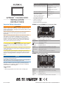
GPSMAP
®
7X3/9X3/12X3
INSTALLATION
INSTRUCTIONS
Important Safety Information
WARNING
Failure to follow these warnings, cautions, and notices could
result in personal injury, damage to the vessel or device, or poor
product performance.
See the Important Safety and Product Information guide in the
product box for product warnings and other important
information.
When connecting the power cable, do not remove the in-line
fuse holder. To prevent the possibility of injury or product
damage caused by fire or overheating, the appropriate fuse
must be in place as indicated in the product specifications. In
addition, connecting the power cable without the appropriate
fuse in place voids the product warranty.
CAUTION
To avoid possible personal injury, always wear safety goggles,
ear protection, and a dust mask when drilling, cutting, or
sanding.
To avoid possible personal injury or damage to the device and
vessel, disconnect the vessel's power supply before beginning
to install the device.
To avoid possible personal injury or damage to the device or
vessel, before applying power to the device, make sure that it
has been properly grounded, following the instructions in the
guide.
NOTICE
For the best possible performance, the device must be installed
according to these instructions.
When drilling or cutting, always check what is on the opposite
side of the surface to avoid damaging the vessel.
Read all installation instructions before proceeding with the
installation. If you experience difficulty during the installation,
contact Garmin
®
Product Support.
Tools Needed
• Drill
• Drill bits appropriate for the device and mounting style
Mounting style Drill bit sizes
Bail with included wood screws 3 mm (
1
/
8
in.)
Flush for the corner of the cutout GPSMAP 7x3: 6.5 mm (
1
/
4
in.)
GPSMAP 9x3: 7.4 mm
(
5
/
16
in.)
GPSMAP 12x3: 13.5 mm
(
9
/
16
in.)
Flush with included wood screws 3.5 mm (
9
/
64
in.)
Flush with included machine
screws and nut plates
3.5 mm (
9
/
64
in.)
3 mm (
1
/
8
in.)
Flush with included machine
screws and tapped holes
M3 tap
• #2 Phillips screwdriver
• Jigsaw or rotary tool
• File and sandpaper
• Marine sealant (recommended)
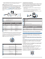
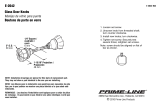
GPSMAP 7x3 and GPSMAP 9x3 Connector View
POWER Power and NMEA
®
0183 network
NETWORK Garmin Marine Network
J1939 J1939 engine network
Ground screw
CVBS IN Composite video in
SONAR 12-pin transducer (Not available on all models)
USB Micro-USB for compatible Garmin card reader
NMEA 2000 NMEA 2000
®
network
2 microSD
®
memory card slots, 32 GB max.
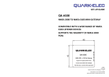
GPSMAP 12x3 Connector View
POWER Power and NMEA 0183 network
SONAR 12-pin transducer (Not available on all models)
HDMI HDMI
®
video out
CVBS IN Composite video in
USB Micro-USB for compatible Garmin card reader
GUID-BF2FF273-008A-482A-A96F-362ADA8996BA v1October 2020

Ground screw
NETWORK Garmin Marine Network
NMEA 2000 NMEA 2000 network
J1939 Engine or J1939 network
2 microSD memory card slots, 32 GB max.
Contacting Garmin Support
• Go to support.garmin.com for help and information, such as
product manuals, frequently asked questions, videos, and
customer support.
• In the USA, call 913-397-8200 or 1-800-800-1020.
• In the UK, call 0808 238 0000.
• In Europe, call +44 (0) 870 850 1241.
Software Update
You may need to update the chartplotter software after
installation. For the instructions on how to update the software,
see the owner's manual at garmin.com/manuals/GPSMAP7x3
-9x3-12x3.
Mounting Considerations
NOTICE
This device should be mounted in a location that is not exposed
to extreme temperatures or conditions. The temperature range
for this device is listed in the product specifications. Extended
exposure to temperatures exceeding the specified temperature
range, in storage or operating conditions, may cause device
failure. Extreme-temperature-induced damage and related
consequences are not covered by the warranty.
When selecting a mounting location, you should observe these
considerations.
• The location should provide optimal viewing as you operate
your boat.
• The location should allow for easy access to all device
interfaces, such as the keypad, touchscreen, and card
reader, if applicable.
• The location must be strong enough to support the weight of
the device and protect it from excessive vibration or shock.
• To avoid interference with a magnetic compass, the device
should not be installed closer to a compass than the
compass-safe distance value listed in the product
specifications.
• The location must allow room for the routing and connection
of all cables.
• The location must not be a flat, horizontal surface. The
location should be in a vertical angle.
The location and viewing angle should be tested before you
install the device. High viewing angles from above and below
the display may result in a poor image.
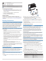
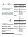
Bail Mounting the Device
NOTICE
If you are mounting the bracket on fiberglass with screws, it is
recommended to use a countersink bit to drill a clearance
counterbore through only the top gel-coat layer. This will help to
avoid cracking in the gel-coat layer when the screws are
tightened.
You can use the bracket to bail mount the device on a flat
surface.
1
Using the bail-mount bracket as a template, mark the pilot
holes .
2
Using a 3 mm (
1
/
8
in.) drill bit, drill the pilot holes.
3
Secure the bail-mount bracket to the surface using the
included washers and wood screws .
4
Install the bail-mount knobs on the sides of the device.
5
Place the device in the bail-mount bracket, and tighten the
bail-mount knobs.
6
Install the trim caps by snapping them in place around the
edges of the device.
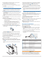
Flush Mounting the Device
NOTICE
Be careful when cutting the hole to flush mount the device.
There is only a small amount of clearance between the case and
the mounting holes, and cutting the hole too large could
compromise the stability of the device after it is mounted.
Use only the included hardware when mounting this device.
Using mounting hardware not provided with the device may
damage the device.
To avoid potential damage to the powder coating, use only the
included screws to mount the device. Using screws other than
the ones included will void your warranty.
Do not use the device as a template when drilling the mounting
holes because this may damage the glass display and void the
warranty. You must only use the included template to correctly
drill the mounting holes.
If you will not have access to the back of the device and the
microSD memory card slots after installations, you should install
the microSD memory card prior to installation.
The included template and hardware can be used to flush mount
the device in your dashboard. There are three options for
hardware based on the mounting surface material.
• You can drill pilot holes and use the included wood screws.
• You can drill holes and use the included nut plates and
machine screws. The nut plates can add stability to a thinner
surface.
• You can punch and tap holes, and use the included machine
screws.
1
Trim the template, and make sure it fits in the location where
you want to mount the device.
2
Secure the template to the mounting location.
3
Using a drill bit according to the list below, drill one or more of
the holes inside the corners of the solid line on the template
to prepare the mounting surface for cutting.
Device Drill bit size
GPSMAP 7x3 6.5 mm (
1
/
4
in.)
GPSMAP 9x3 7.4 mm (
5
/
16
in.)
GPSMAP 12x3 13.5 mm (
9
/
16
in.)
2

4
Using a jigsaw or a rotary tool, cut the mounting surface
along the inside line on the template.
5
Place the device in the cutout to test the fit.
6
If necessary, use a file and sandpaper to refine the size of
the cutout.
7
If necessary, remove the trim caps.
NOTICE
Use a plastic pry tool when possible. Using a metal pry tool,
such as a screwdriver, can damage the trim caps and the
device.
8
After the device fits correctly in the cutout, ensure the
mounting holes on the device line up with the hole locations
on the template.
NOTE: GPSMAP 12x3 models have six mounting holes.
GPSMAP 9x3 and GPSMAP 7x3 models have four mounting
holes.
9
If the mounting holes on the device do not line up, mark the
new hole locations.
10
Based on your mounting method, drill or punch and tap the
outer holes on the template:
• For the included wood screws, drill 3.5 mm (
9
/
64
in.) holes,
and skip to step 18.
• For the included nut plate and machine screws, drill
3.5 mm (
9
/
64
in.) holes in the outer hole locations.
• For the included machine screws without the nut plate,
punch and tap M3 holes, and skip to step 18.
11
If you are using a nut plate, starting in one corner of the
template, place a nut plate over the hole drilled in the
previous step.
The other hole on the nut plate should line up with the
inner hole on the template.
12
If the inner hole on the nut plate does not line up with the
inner hole on the template, mark the new hole location.
13
If you are using a nut plate, using a 3 mm (
1
/
8
in.) drill bit, drill
a hole in the inner hole location.
14
Repeat to verify placement of the remaining nut plates and
holes on the template.
15
Remove the template from the mounting surface.
16
Starting in one corner of the mounting location, place a nut
plate on the back of the mounting surface, lining up the
holes.
The raised portion of the nut plate should fit into the inner
hole.
17
Secure the nut plates to the mounting surface by fastening
the pan head machine screws through the inner holes.
18
Install the foam gasket on the back of the device.
The pieces of the foam gasket have adhesive on the back.
Make sure you remove the protective liner before installing
them on the device.
19
If you will not have access to the back of the device after you
mount it, connect all necessary cables and install microSD
cards in the back of the device before placing it into the
cutout.
NOTICE
To prevent corrosion of the metal contacts, cover unused
connectors with the attached weather caps.
20
Apply marine sealant between the mounting surface and the
device to properly seal and prevent leakage behind the
dashboard.
21
If you will have access to the back of the device, apply
marine sealant around the cutout.
22
Place the device into the cutout.
23
Secure the device to the mounting surface using the flat head
machine screws or the included wood screws.
24
Wipe away all excess marine sealant.
25
Install the trim caps by snapping them in place around the
edges of the device.
Connection Considerations
After connecting the cables to the device, tighten the locking
rings to secure each cable.
Power/NMEA 0183 Cable
• The wiring harness connects the device to power, NMEA
0183 devices, and a lamp or a horn for visible or audible
alerts.
• If it is necessary to extend the NMEA 0183 or alarm wires,
you must use 22 AWG (.33 mm²) wire.
• This cable provides one differential NMEA 0183 input and
output port.
Item Wire Color Wire Function
Red Power
Black Ground (power and NMEA 0183)
Blue NMEA 0183 TxA (Out +)
Gray NMEA 0183 TxB (Out -)
Brown NMEA 0183 RxA (In +)
Violet NMEA 0183 RxB (In -)
Orange Accessory on
Yellow Alarm low
Connecting the Wiring Harness to Power
WARNING
When connecting the power cable, do not remove the in-line
fuse holder. To prevent the possibility of injury or product
damage caused by fire or overheating, the appropriate fuse
must be in place as indicated in the product specifications. In
3

addition, connecting the power cable without the appropriate
fuse in place voids the product warranty.
1
Route the wiring harness to the power source and to the
device.
2
Connect the red wire to the positive (+) battery terminal, and
connect the black wire to the negative (-) battery terminal.
3
If necessary, install the locking ring and O-ring on the end of
the wiring harness.
4
Insert the cable into the POWER connector on the back of
the device, pushing firmly.
5
Turn the locking ring clockwise to attach the cable to the
device.
Additional Grounding Consideration
This device should not need additional chassis grounding in
most installation situations. If you experience interference, the
grounding screw on the housing can be used to connect the
device to the water ground of the boat to help avoid the
interference.
Garmin Marine Network Considerations
NOTICE
A Garmin Marine Network PoE Isolation Coupler
(010-10580-10) must be used when connecting any third-party
device, such as a FLIR
®
camera, to a Garmin Marine Network.
Connecting a Power over Ethernet (PoE) device directly to a
Garmin Marine Network chartplotter damages the Garmin
chartplotter and may damage the PoE device. Connecting any
third-party device directly to a Garmin Marine Network
chartplotter will cause abnormal behavior on the Garmin
devices, including the devices not properly turning off or the
software becoming inoperable.
This device can connect to additional Garmin Marine Network
devices to share data such as radar, sonar, and detailed
mapping. When connecting Garmin Marine Network devices to
this device, observe these considerations.
• All devices connected to the Garmin Marine Network must be
connected to the same ground. If multiple power sources are
used for Garmin Marine Network devices, you must tie all
ground connections from all power supplies together using a
low resistance connection or tie them to a common ground
bus bar, if available.
• A Garmin Marine Network cable must be used for all Garmin
Marine Network connections.
◦ Third-party CAT5 cable and RJ45 connectors must not be
used for Garmin Marine Network connections.
◦ Additional Garmin Marine Network cables and connectors
are available from your Garmin dealer.
• The NETWORK ports on the device each act as a network
switch. Any compatible device can be connected to any
NETWORK port to share data with all devices on the boat
connected by a Garmin Marine Network cable.
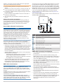
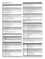
NMEA 2000 Considerations
NOTICE
If you are connecting to an existing NMEA 2000 network,
identify the NMEA 2000 power cable. Only one NMEA 2000
power cable is required for the NMEA 2000 network to operate
properly.
A NMEA 2000 Power Isolator (010-11580-00) should be used in
installations where the existing NMEA 2000 network
manufacturer is unknown.
If you are installing a NMEA 2000 power cable, you must
connect it to the boat ignition switch or through another in-line
switch. NMEA 2000 devices will drain your battery if the NMEA
2000 power cable is connected to the battery directly.
This device can connect to a NMEA 2000 network on your boat
to share data from NMEA 2000 compatible devices such as a
GPS antenna or a VHF radio. The included NMEA 2000 cables
and connectors allow you to connect the device to your existing
NMEA 2000 network. If you do not have an existing NMEA 2000
network you can create a basic one using cables from Garmin.
If you are unfamiliar with NMEA 2000, you should read the
Technical Reference for NMEA 2000 Products at garmin.com
/manuals/nmea_2000.
The port labeled NMEA 2000 is used to connect the device to a
standard NMEA 2000 network.
Item Description
NMEA 2000 compatible Garmin device
GPS antenna
Ignition or in-line switch
NMEA 2000 power cable
NMEA 2000 drop cable
12 Vdc power source
NMEA 2000 terminator or backbone cable
NMEA 2000 T-connector
NMEA 2000 terminator or backbone cable
NMEA 0183 Connection Considerations
• The chartplotter provides one Tx (transmit) port and one Rx
(receive) port.
• Each port has 2 wires, labeled A and B according to the
NMEA 0183 convention. The corresponding A and B wires of
each internal port should be connected to the A (+) and B (-)
wires of the NMEA 0183 device.
• You can connect one NMEA 0183 device to the Rx port to
input data to this chartplotter, and you can connect up to
three NMEA 0183 devices in parallel to the Tx port to receive
data output by this chartplotter.
• See the NMEA 0183 device installation instructions to identify
the transmit (Tx) and receive (Rx) wires.
• You must use 28 AWG, shielded, twisted-pair wiring for
extended runs of wire. Solder all connections and seal them
with heat-shrink tubing.
• Do not connect the NMEA 0183 data wires from this device
to power ground.
• The power cable from the chartplotter and the NMEA 0183
devices must be connected to a common power ground.
• The internal NMEA 0183 ports and communication protocols
are configured on the chartplotter. See the NMEA 0183
section of the chartplotter owner's manual for more
information.
4

• See the chartplotter owner's manual for a list of the approved
NMEA 0183 sentences that the chartplotter supports.
NMEA 0183 Device Connections
This diagram illustrates two-way connections for both sending
and receiving data. You can also use this diagram for one-way
communication. To receive information from a NMEA 0183
device, refer to items , , , and when connecting the
Garmin device. To transmit information to a NMEA 0183 device,
refer to items , , , and when connecting the Garmin
device.
Item Description
Power source
Power/NMEA 0183 cable
NMEA 0183 device
Item Garmin Wire Function Garmin Wire
Color
NMEA 0183 Device
Wire Function
Power Red Power
Power ground Black Power ground
Data ground Black Data ground
Rx/A (In +) Brown Tx/A (Out +)
Rx/B (In -) Violet Tx/B (Out -)
Tx/A (Out +) Blue Rx/A (In +)
Tx/B (Out -) Gray Rx/B (In -)
If the NMEA 0183 device has only one input (receive, Rx) wire
(no A, B, +, or -), you must leave the gray wire unconnected.
If the NMEA 0183 device has only one output (transmit, Tx) wire
(no A, B, +, or -), you must connect the violet wire to ground.
NMEA 0183 and Power Cable Pinout
Pin Number Wire Function Wire Color
NMEA 0183 Tx/A (Out
+)
Blue
NMEA 0183 Rx/A (In
+)
Brown
NMEA 0183 Tx/B (Out
-)
Gray
NMEA 0183 Rx/B (In
-)
Violet
Alarm Yellow
Accessory on Orange
Ground (shield) Black
VIN Red
Lamp and Horn Connections
The device can be used with a lamp, a horn, or both, to sound or
flash an alert when the chartplotter displays a message. This is
optional, and the alarm wire is not necessary for the device to
function normally. When connecting the device to a lamp or
horn, observe these considerations.
• The alarm circuit switches to a low-voltage state when the
alarm sounds.
• The maximum current is 100 mA, and a relay is needed to
limit the current from the chartplotter to 100 mA.
• To manually toggle visual and audible alerts, you can install
single-pole, single-throw switches.
Item Description
Power source
Power cable
Horn
Lamp
Relay (100 mA coil current)
Toggle switches to enable and disable lamp or horn alerts
Item Wire Color Wire Function
Red Power
Black Ground
Yellow Alarm
J1939 Engine Network Connection Considerations
NOTICE
You must use a Garmin GPSMAP J1939 accessory cable when
connecting the chartplotter to the J1939 engine network to
prevent corrosion due to moisture. Using a different cable voids
your warranty.
If you have an existing engine network on your boat, it should
already be connected to power. Do not add any additional power
supply.
This chartplotter can connect to an engine network on your boat
to read data from compatible devices such as certain engines.
The engine network follows a standard and uses proprietary
messages.
You should connect only one chartplotter to one engine network.
Connecting more than one chartplotter to one engine network
may result in unexpected behavior.
The port labeled J1939 is used to connect the device to the
existing engine network. You must route the cable within 6 m
(20 ft.) of the engine network backbone.
The Garmin GPSMAP J1939 accessory cable requires
connection to a power source and proper termination. For more
information on connecting to your engine network, see the
manufacturer's engine documentation.
5

Pin Wire Color Description
Bare Shield
Red Power, positive
Black Power, negative
White CAN High
Blue CAN Low
Composite Video Considerations
This chartplotter allows video input from composite video
sources using the port labeled CVBS IN. When connecting
composite video, you should observe these considerations.
• The CVBS IN port uses a BNC connector. You can use a
BNC to RCA adapter to connect a composite-video source
with RCA connectors to the CVBS IN port.
• Video is shared across the Garmin Marine Network, but it is
not shared across the NMEA 2000 network.
HDMI Out Video Considerations
NOTICE
To prevent corrosion due to moisture, you must use Garmin
GPSMAP accessory cables when connecting the chartplotter to
the video display. Using different cables voids your warranty.
The GPSMAP 12x3 chartplotter has HDMI out capability to
duplicate the chartplotter screen on another device, such as a
television or monitor.
The Garmin GPSMAP HDMI accessory cable is 4.5 m (15 ft.)
long. If you need a longer cable, you should use an active HDMI
cable only. You need an HDMI coupler to connect the two HDMI
cables.
You must make all cable connections in a dry environment.
Item Description
GPSMAP 12x3 chartplotter
GPSMAP HDMI cable (HDMI)
Display with an HDMI In port, such as a computer or television
Dry environment, protected from moisture
Installing the Ferrite Beads on the Cables
To comply with regulations and to reduce noise, you can install
the included ferrite beads on the specified cables.
GPSMAP 12x3 Power cable and transducer cable
GPSMAP 7x3/9x3 Power cable, transducer cable,
and USB cable
Securely snap one ferrite bead around each of the specified
cables, as close to the connectors as possible.
Specifications
All Models
Temperature range From -15° to 55°C (from 5° to 131°F)
Material Polycarbonate plastic and die-cast
aluminum
Water rating IEC 60529 IPX7
1
Input voltage From 10 to 32 Vdc
Fuse 6 A, 125 V fast-acting
NMEA 2000 LEN @ 9 Vdc 2
NMEA 2000 draw 75 mA max.
USB connector Micro-USB for compatible Garmin card
reader
2
Wireless frequency 2.4 GHz @ 18.3 dBm maximum
Memory card 2 microSD card slots; 32 GB max. card size
GPSMAP 7x3
Dimensions (W × H × D) 192.3 × 140.3 × 74.1 mm (7
9
/
16
× 5
1
/
2
× 2
15
/
16
in.)
Clearance to next obstruction 27.8 mm (2 in.)
Display size (W × H) 154.6 × 91.0 mm (6
1
/
16
× 3
9
/
16
in.)
17.8 cm (7.0 in.) diagonal
Display resolution WSVGA, 1024 × 600 pixels
Weight 1.3 kg (2.8 lb.)
Compass-safe distance 35 cm (13.78 in.)
Max. power usage at 10 Vdc Non-sonar models: 17.6 W
Sonar models: 35.9 W
Typical current draw at 12 Vdc Non-sonar models: 1.08 A
Sonar models: 1.18 A
Max. current draw at 12 Vdc Non-sonar models: 1.45 A
Sonar models: 2.96 A
GPSMAP 9x3
Dimensions (W × H × D) 233.0 × 162.3 × 75.8 mm (9
3
/
16
× 6
3
/
8
× 3 in.)
Clearance to next obstruction 33.2 mm (1
5
/
8
in.)
Display size (W × H) 198.7 × 111.8 mm (7
13
/
16
× 4
3
/
8
in.)
22.9 cm (9.0 in.) diagonal
Display resolution WXGA, 1280 ×720 pixels
Weight 1.6 kg (3.6 lb.)
Compass-safe distance 30 cm (11.81 in.)
Max. power usage at 10 Vdc Non-sonar models: 22.0 W
Sonar models: 40.2 W
Typical current draw at 12 Vdc Non-sonar models: 1.34 A
Sonar models: 1.37 A
Max. current draw at 12 Vdc Non-sonar models: 1.78 A
Sonar models: 3.20 A
GPSMAP 12x3
Dimensions (W × H × D) 308.3 × 227.6 × 81.8 mm (12
1
/
8
×
8
15
/
16
× 3
1
/
4
in.)
Clearance to next obstruction 18.7 mm (
3
/
4
in.)
Display size (W × H) 262.1 × 164.2 mm (10
15
/
16
× 6
7
/
16
in.)
30.7 cm (12.1 in.) diagonal
Display resolution WXGA, 1280 × 800 pixels
Weight 3.0 kg (6.6 lb.)
Compass-safe distance 45 cm (17.72 in.)
Max. power usage at 10 Vdc Non-sonar models: 26.5 W
Sonar models: 43.0 W
Typical current draw at 12 Vdc Non-sonar models: 1.67 A
Sonar models: 1.68 A
Max. current draw at 12 Vdc Non-sonar models: 2.15 A
Sonar models: 3.56 A
1
The device withstands incidental exposure to water of up to 1 m for up to 30 min.
For more information, go to www.garmin.com/waterrating.
2
Only compatible Garmin card readers recommended. Third-party card readers
are not guaranteed to be fully compatible.
6

NMEA 2000 PGN Information
Transmit and Receive
PGN Description
059392 ISO acknowledgment
059904 ISO request
060160 ISO transport protocol: Data transfer
060416 ISO transport protocol: Connection management
060928 ISO address claimed
065240 Commanded address
126208 Request group function
126996 Product information
126998 Configuration information
127237 Heading/track control
127245 Rudder
127250 Vessel heading
127258 Magnetic variance
127488 Engine parameters: Rapid update
127489 Engine parameters: Dynamic
127493 Transmission parameters: Dynamic
127505 Fluid level
127508 Battery status
128259 Speed: Water referenced
128267 Water depth
129025 Position: Rapid update
129026 COG and SOG: Rapid update
129029 GNSS position data
129283 Cross track error
129284 Navigation data
129539 GNSS DOPs
129540 GNSS satellites in view
130060 Label
130306 Wind data
130310 Environmental parameters (obsolete)
130311 Environmental parameters (obsolete)
130312 Temperature (obsolete)
Transmit
PGN Description
126464 Transmit and receive PGN list group function
126984 Alert Response
127497 Trip parameters: Engine
Receive
PGN Description
065030 Generator average basic AC quantities (GAAC)
126983 Alert
126985 Alert text
126987 Alert threshold
126988 Alert value
126992 System time
127251 Rate of turn
127257 Attitude
127498 Engine parameters: Static
127503 AC input status (obsolete)
127504 AC output status (obsolete)
127506 DC detailed status
127507 Charger status
127509 Inverter status
128000 Nautical leeway angle
PGN Description
128275 Distance log
129038 AIS class A position report
129039 AIS class B position report
129040 AIS class B extended position report
129044 Datum
129285 Navigation: Route, waypoint information
129794 AIS class A static and voyage related data
129798 AIS SAR aircraft position report
129799 Radio frequency/mode/power
129802 AIS safety-related broadcast message
129808 DSC call Information
129809 AIS class B "CS" static data report, part A
129810 AIS class B "CS" static data report, part B
130313 Humidity
130314 Actual pressure
130316 Temperature: Extended range
130576 Trim tab status
130577 Direction data
NMEA 0183 Information
Transmit
Sentence Description
GPAPB APB: Heading or track controller (autopilot) sentence "B"
GPBOD BOD: Bearing (origin to destination)
GPBWC BWC: Bearing and distance to waypoint
GPGGA GGA: Global positioning system fix data
GPGLL GLL: Geographic position (latitude and longitude)
GPGSA GSA: GNSS DOP and active satellites
GPGSV GSV: GNSS satellites in view
GPRMB RMB: Recommended minimum navigation information
GPRMC RMC: Recommended minimum specific GNSS data
GPRTE RTE: Routes
GPVTG VTG: Course over ground and ground speed
GPWPL WPL: Waypoint location
GPXTE XTE: Cross track error
PGRME E: Estimated error
PGRMM M: Map datum
PGRMZ Z: Altitude
SDDBT DBT: Depth below transducer
SDDPT DPT: Depth
SDMTW MTW: Water temperature
SDVHW VHW: Water speed and heading
Receive
Sentence Description
DPT Depth
DBT Depth below transducer
MTW Water temperature
VHW Water speed and heading
WPL Waypoint location
DSC Digital selective calling information
DSE Expanded digital selective calling
HDG Heading, deviation, and variation
HDM Heading, magnetic
MWD Wind direction and speed
MDA Meteorological composite
MWV Wind speed and angle
VDM AIS VHF data-link message
7

You can purchase complete information about National Marine
Electronics Association (NMEA) format and sentences from
www.nmea.org.
J1939 Information
The chartplotter can receive J1939 sentences. The chartplotter
cannot transmit over the J1939 network.
Description PGN SPN
Engine percent load at current speed 61443 92
Engine speed 61444 190
Engine manifold exhaust gas temperature - right manifold 65031 2433
Engine manifold exhaust gas temperature - left manifold 65031 2434
Engine auxiliary coolant 65172
Active diagnostic trouble codes 65226
Vehicle distance 65248
Water in fuel indicator 65279
Engine wait to start lamp 65252 1081
Engine over speed test 65252 2812
Engine air shutoff command status 65252 2813
Engine alarm output command status 65252 2814
Engine total hours of operation 65253 247
Navigation-based vehicle speed 65256 517
Engine fuel temperature 1 65262 174
Engine oil temperature 1 65262 175
Engine fuel delivery pressure 65263 94
Engine oil pressure 65263 100
Engine coolant pressure 65263 109
Engine coolant temperature 65263 110
Engine coolant level 65263 111
Engine fuel rate 65266 183
Engine average fuel economy 65266 185
Engine intake manifold #1 pressure 65270 102
Battery potential / power input 1 65271 168
Transmission oil temperature 65272 177
Transmission oil pressure 65272 127
Fuel level 65276 96
Engine oil filter differential pressure 65276 969
物質宣言
部件名称 有毒有害物质或元素
铅 汞 镉 六价铬 多溴联苯 多溴二苯醚
印刷电路板组件 X O O O O O
屏幕/背光 X O O O O O
金属零件 X O O O O O
电缆 电缆组件 连接器 X O O O O O
本表格依据 SJ/T11364 的规定编制。
O: 代表此种部件的所有均质材料中所含的该种有害物质均低于
(GB/T26572) 规定的限量
X: 代表此种部件所用的均质材料中, 至少有一类材料其所含的有害
物质高于
(GB/T26572) 规定的限量
*該產品說明書應提供在環保使用期限和特殊標記的部分詳細講解
產品的擔保使用條件。
產
品
中国微功率无线电发射设备合规
一 ) 工作于 2.4 GHz 频段的 ANT 技术无线遥控设备 , 使用频率 :
2.4 GHz, 发射功率限值 : <10 mW (e.i.r.p.)(e.i.r.p), 频率容限 :
<170 kHz
二) 不得擅自改变使用场景或使用条件、扩大发射频率范围、加
大发射功率(包括额外加装射频功率放大器),不得擅自更改发
射天线;
三) 不得对其他合法的无线电台(站)产生有害干扰,也不得提
出免受有害干扰保护;
四) 应当承受辐射射频能量的工业、科学及医疗( ISM )应用设
备的干扰或其他合法的无线电台(站)干扰;
五) 如对其他合法的无线电台(站)产生有害干扰时,应立即停
止使用,并采取措施消除干扰后方可继续使用;
六) 在航空器内和依据法律法规、国家有关规定、标准划设的射
电天文台、气象雷达站、卫星地球站(含测控、测距、接收、导
航站)等军民用无线电台(站)、机场等的电磁环境保护 区域内
使用微功率设备,应当遵守电磁环境保护及相关行业主管部门的
规定;
八) 微功率设备使用时温度 -15–55℃ 和电压 10–32 Vdc 。
低功率電波輻射電機管理宣告
本產品謹遵循中華民國國家通訊傳播委員會所頒布電信管理法,
並經驗證通過合格,請使用者遵循相關電信法規以避免違反規定
受罰。若使用者欲攜帶本機至其他國家應用,也請遵循該地區或
國家之相關法令限制。根據國家通訊傳播委員會低功率射頻器材
技術規範規定
3.8.2 章節:
取得審驗證明之低功率射頻器材,非經核准,公司、商號或使用
者均不得擅自變更頻率、加大功率或變更原設計之特性及功能。
低功率射頻器材之使用不得影響飛航安全及干擾合法通信;經發
現有干擾現象時,應立即停用,並改善至無干擾時方得繼續使
用。
前項合法通信,指依電信法規定作業之無線電通信。低功率射頻
器材須忍受合法通信或工業、科學及醫療用電波輻射性電機設備
之干擾。
連絡地址
製造銷售:台灣國際航電股份有限公司
聯絡地址:新北市汐止區樟樹二路 68 號
電 話:(02)2642-8999
客服專線:(02)2642-9199
© 2020 Garmin Ltd. or its subsidiaries
Garmin
®
, the Garmin logo, and GPSMAP
®
are trademarks of Garmin Ltd. or its
subsidiaries, registered in the USA and other countries. These trademarks may not be
used without the express permission of Garmin.
NMEA
®
, NMEA 2000
®
, and the NMEA 2000 logo are registered trademarks of the
National Marine Electronics Association.
HDMI
®
is a registered trademark of HDMI
Licensing, LLC. The SDHC logo is a trademark of SD-3C, LLC. Wi‑Fi
®
is a registered
trademark of Wi-Fi Alliance Corporation.
GPSMAP 1223/1243/1253/1223xsv/1243xsv/1253xsv, GPSMAP 723/743/753/723xsv/
743xsv/753xsv, GPSMAP 923/943/953/923xsv/943xsv/953xsvn
M/N: A0387, B03873, A03875 FCC: IPH-03873, IPH-03875 IC: 1792A-03873,
1792A-03875 Garmin Corporation
© 2020 Garmin Ltd. or its subsidiaries
support.garmin.com
-
 1
1
-
 2
2
-
 3
3
-
 4
4
-
 5
5
-
 6
6
-
 7
7
-
 8
8


Garmin GPS Map 7x3 Installation guide
- Type
- Installation guide
- This manual is also suitable for
Ask a question and I''ll find the answer in the document
Finding information in a document is now easier with AI
Related papers
-
Garmin GPSMAP 1242 Touch Owner's manual
-
Garmin GPSMAP 722xs Plus bundel Owner's manual
-
Garmin GPSMAP® 7616xsv Owner's manual
-
Garmin GPSMAP® 8424 MFD Owner's manual
-
Garmin GPSMAP 10X2/12X2 Series Owner's manual
-
Garmin GPSMAP User manual
-
Garmin GPSMAP® 7412 Installation guide
-
Garmin GPSMAP® 1022 Owner's manual
-
Garmin GPSMAP® 942 Owner's manual
-
Garmin GPSMAP 722xs og GMR 18 HD+-pakke Owner's manual
Other documents
-
Standard Horizon Wiring Garmin GPSMap 640 Owner's manual
-
Yamaha CL7 Installation guide
-
Wet Sounds WS-NMEA-TR Owner's manual
-
 Prime-Line E 2642 Installation guide
-
GME G-combo G142CFD User manual
-
Humminbird Dual NMEA Y-CABLE Installation guide
-
 Quark-Elec QK-AS00 Installation guide
-
FLIR M-Series Owner's manual
-
 veratron LINK UP 2-in-1 User manual
-
VDO AcquaLink Nav Box Installation guide


