Toro E-Z Vac Complete Twin Bagger, TITAN Zero-Turn-Radius Riding Mower User manual

Category
Lawnmowers
Type
User manual
FormNo.3436-949RevA
E-ZVac
CompleteTwinBagger
TITAN
®
Zero-Turn-RadiusRidingMower
ModelNo.79346—SerialNo.400000000andUp
Registeratwww.Toro.com.
OriginalInstructions(EN)
*3436-949*A
WARNING
CALIFORNIA
Proposition65Warning
Useofthisproductmaycauseexposure
tochemicalsknowntotheStateof
Californiatocausecancer,birthdefects,
orotherreproductiveharm.
Introduction
Readthisinformationcarefullytolearnhowtooperate
andmaintainyourproductproperlyandtoavoid
injuryandproductdamage.Youareresponsiblefor
operatingtheproductproperlyandsafely.
Visitwww.Toro.comforproductsafetyandoperation
trainingmaterials,accessoryinformation,helpnding
adealer,ortoregisteryourproduct.
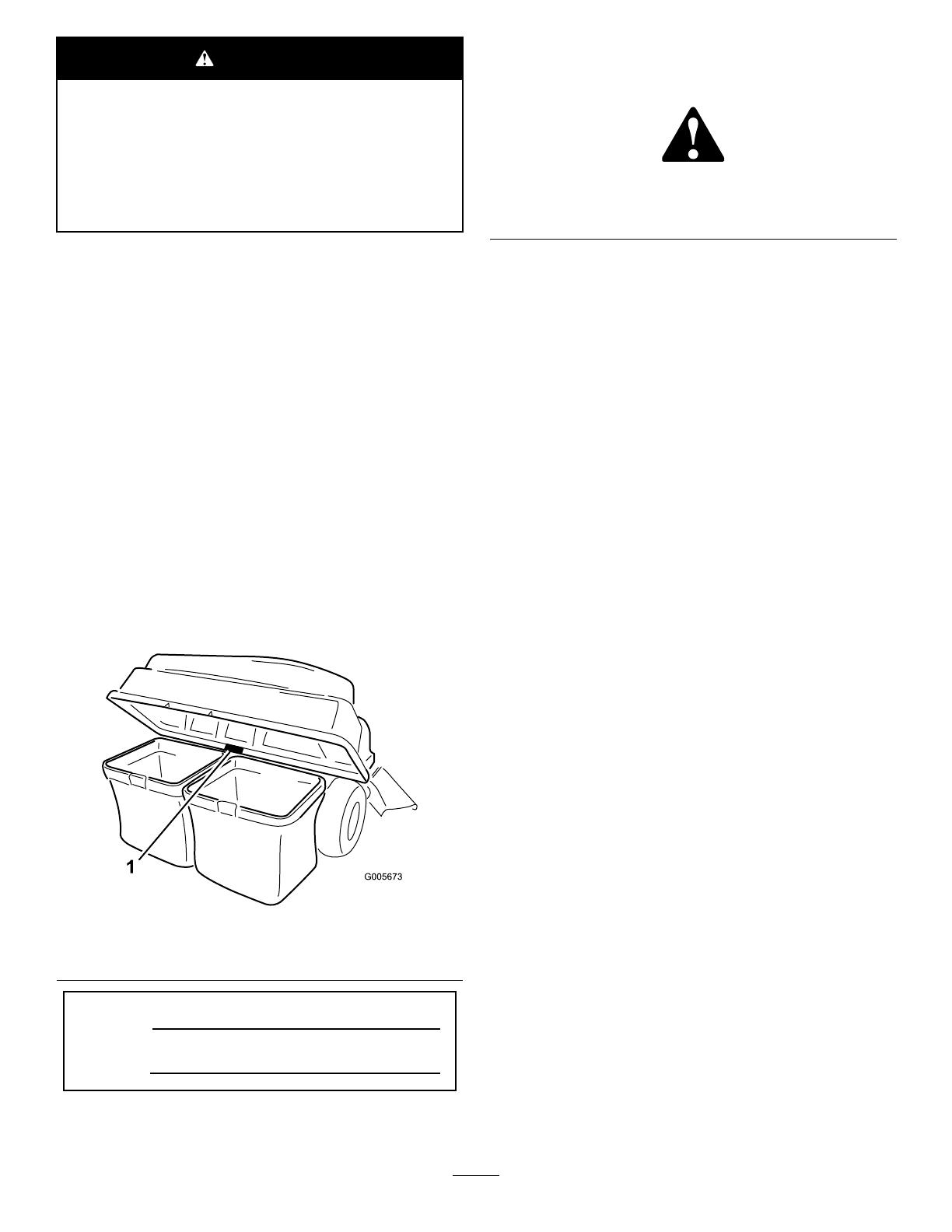
Wheneveryouneedservice,genuineT oroparts,or
additionalinformation,contactanAuthorizedService
DealerorT oroCustomerServiceandhavethemodel
andserialnumbersofyourproductready.Figure1
identiesthelocationofthemodelandserialnumbers
ontheproduct.Writethenumbersinthespace
provided.
g005673
Figure1
1.Modelandserialnumberlocation
ModelNo.
SerialNo.
Thismanualidentiespotentialhazardsandhas
safetymessagesidentiedbythesafety-alertsymbol
(Figure2),whichsignalsahazardthatmaycause
seriousinjuryordeathifyoudonotfollowthe
recommendedprecautions.
g000502
Figure2
1.Safety-alertsymbol
Thismanualuses2wordstohighlightinformation.
Importantcallsattentiontospecialmechanical
informationandNoteemphasizesgeneralinformation
worthyofspecialattention.
Contents
Safety.......................................................................3
TowingSafety.....................................................3
SafetyandInstructionalDecals..........................4
Setup........................................................................5
1PreparingtheMachine.....................................6
2InstallingtheWeight.........................................6
3RemovingtheGrassDeectorandBelt
Cover..............................................................7
4InstallingtheBafeandBlower
Support...........................................................8
5InstallingthePulleyAssembly,BeltCover,
andShoulderBolt..........................................10
6InstallingtheAttachmentMount.....................10
7InstallingtheLatchRod..................................12
8AssemblingtheBaggerTop...........................13
9InstallingtheBaggerT op................................14
10InstallingtheBlowerAssembly.....................14
11InstallingtheBlowerBeltandPowered
BaggerCover................................................16
12InstallingtheDischargeTubes.....................17
Operation................................................................19
EmptyingtheGrassBags.................................20
ClearingObstructionsfromtheBagger.............21
RemovingtheBagger.......................................21
OperatingTips.................................................22
Maintenance...........................................................23
RecommendedMaintenanceSchedule(s)...........23
PreparingforMaintenance...............................23
CleaningtheHoodScreen................................23
CleaningtheBaggerandBags.........................24
InspectingtheBlowerBelt................................24
ReplacingtheBlowerBelt.................................24
InspectingtheBagger.......................................24
InspectingtheMowerBlades............................24
Storage...................................................................25
StoringtheBaggerAttachment.........................25
Troubleshooting......................................................26
©2019—TheToro®Company
8111LyndaleAvenueSouth
Bloomington,MN55420
2
Contactusatwww.Toro.com.
PrintedintheUSA
AllRightsReserved
Safety
Becomefamiliarwiththesafeoperationofthe
equipment,withtheoperatorcontrols,andsafety
signs.
Useextracarewithgrasscatchersorother
attachments.Thesecanchangetheoperating
characteristicsandthestabilityofthemachine.
Followthemanufacturer'srecommendations
foraddingorremovingwheelweightsor
counterweightstoimprovestability.
Donotuseagrasscatcheronsteepslopes.A
heavygrasscatchercouldcauselossofcontrol
oroverturnthemachine.
Slowdownanduseextracareonhillsides.Be
suretotravelintherecommendeddirectionon
hillsides.Turfconditionscanaffectthestabilityof
themachine.Useextremecautionwhileoperating
neardrop-offs.
Keepallmovementonslopesslowandgradual.
Donotmakesuddenchangesinspeed,direction,
orturning.
Thegrasscatchercanobstructtheviewtothe
rear.Useextracarewhenoperatinginreverse.
Usecarewhenloadingorunloadingthemachine
intoatrailerortruck.
Neveroperatewiththedischargedeectorraised,
removedoraltered,unlessusingagrasscatcher.
Keephandsandfeetawayfrommovingparts.Do
notmakeadjustmentswiththeenginerunning.
Parkthemachineonlevelground,disengage
thedrives,chockthewheels,andshutoffthe
enginebeforeleavingtheoperator'spositionfor
anyreasonincludingemptyingthegrasscatcher
oruncloggingthechute.
Ifyouremovethegrasscatcher,besuretoinstall
anydischargedeectororguardthatmighthave
beenremovedtoinstallthegrasscatcher.Donot
operatethemowerwithouteithertheentiregrass
catcherorthegrassdeectorinplace.
Shutofftheenginebeforeremovingthegrass
catcheroruncloggingthechute.
Donotleavegrassinthegrasscatcherfor
extendedperiodsoftime.
Grasscatchercomponentsaresubjecttowear,
damageanddeterioration,whichcouldexpose
youtomovingpartsorallowobjectstobethrown.
Frequentlycheckcomponentsandreplacewith
themanufacturer'srecommendedparts,when
necessary.
TowingSafety
Donotattachtowedequipmentexceptatthehitch
point.
Followtheattachmentmanufacturer's
recommendationforweightlimitsfortowed
equipmentandtowingonslopes.
Neverallowchildrenorothersinorontowed
equipment.
Onslopes,theweightofthetowedequipmentmay
causelossoftractionandlossofcontrol.Reduce
towedweightandslowdown.
Stoppingdistanceincreaseswiththeweightofthe
towedload.Travelslowlyandallowextradistance
tostop.
Makewideturnstokeeptheattachmentclearof
themachine.
Donottowaloadthatweighsmorethanthe
towingmachine.
3
SafetyandInstructionalDecals
Safetydecalsandinstructionsareeasilyvisibletotheoperatorandarelocatednearanyarea
ofpotentialdanger.Replaceanydecalthatisdamagedormissing.
decal136-4164
136-4164
1.Warning—readtheOperatorsManual.4.Cutting/dismembermenthazard,impeller—keepawayfrom
movingparts;keepallguardsandcoversinplace.
2.Warning—hearingprotectionmustbeworn.
5.Cutting/dismembermenthazard,impeller—disengagethe
PTO,removethekey,andwaitforallmovingpartstostop.
3.Thrownobjecthazard—donotoperatetheblowerwithoutthe
entiresysteminstalledandlatched.
6.Warning;lossoftraction—donotoperatewithonly
counterbalanceweightsinstalled;donotoperatewithonly
E-ZVacinstalled;operateonlywithbothE-ZVacand
counterbalanceweightsinstalled.
decal109-6809
109-6809
1.Crushinghazardofhand—donotremovethewholebaggerfromthemachine;openthebaggertopandthenremovethebag(s)
fromthebagger.Donotremovethebaggertopwhenitisclosed;openthebaggertopandthenremoveit.
decal133-8061
133-8061
4
Setup
LooseParts
Usethechartbelowtoverifythatallpartshavebeenshipped.
ProcedureDescription
Qty.
Use
1
Nopartsrequired
Preparethemachine.
Weighttray1
Leftweight-traymount
1
Rightweight-traymount1
Suitcaseweight—16kg(35lb)
1
Retainingrod1
Bolt(3/8x1-1/4inches)
2
Flangenut(3/8inch)
4
Carriagebolt(3/8x1inch)
2
2
Self-tappingbolt(5/16x3/4inch)
2
Installtheweight.
3
Nopartsrequired
Removethegrassdeectorandbelt
cover.
Blowersupport1
Hexwasher-headscrew(3/8x3/4inch)
2
Bafe
1
Carriagebolt(5/16x3/4inch)
4
4
Flangenut(5/16inch)
4
Installthebafeandblowersupport.
Pulleyassembly1
5
Beltcover1
Installthepulleyassemblyandbelt
cover.
Stabilizerbracket
1
Carriagebolt(5/16x3/4inch)
2
Locknut(5/16inch)
4
Self-tappingscrew(5/16x3/4inch)
2
Bolt(5/16x1inch)
2
Pivotframe
1
Hairpincotter2
Rod2
6
Washer2
Installtheattachmentmount.
Latchrod1
7
Hairpincotter1
Installthelatchrod.
Baggertop1
Baggerscreen1
8
Hairpincotter2
Assemblethebaggertop.
9
GrassBag
2Installthebaggertop.
10
Blowerassembly1Installtheblowerassembly.
Poweredbaggercover1
11
Blowerbelt1
Installtheblowerbeltandpowered
baggercover.
Uppertube1
Screw(1/4x3/4inches)
2
Washer(1/4inch)
2
Locknut(1/4inch)
2
12
Lowertube1
Installthedischargetubes.
5
Determinetheleftandrightsidesofthemachinefromthenormaloperatingposition.
1
PreparingtheMachine
NoPartsRequired
Procedure
Performthefollowingproceduretopreparethe
machineforattachingtheblowerandnishingkit.
1.Parkthemachineonalevelsurface.
2.Disengagetheblade-controlswitch,engage
theparkingbrake,andmovethemotion-control
leversoutwardtotheNEUTRAL-LOCKposition.
3.Shutofftheengineandremovethekey.
4.Ensurethatthemachineissecurefrom
movementbeforeyoubegintoworkonit.
5.Repairallbentordamagedareasofmachine
deckandreplaceanymissingparts.
6.Cleanthemachineofanydebrisonthemachine
deckorrearpartofthemachinetoease
installation.
2
InstallingtheWeight
Partsneededforthisprocedure:
1Weighttray
1
Leftweight-traymount
1Rightweight-traymount
1
Suitcaseweight—16kg(35lb)
1Retainingrod
2
Bolt(3/8x1-1/4inches)
4
Flangenut(3/8inch)
2
Carriagebolt(3/8x1inch)
2
Self-tappingbolt(5/16x3/4inch)
Procedure
CAUTION
Thebaggerchangestheweightdistributionof
themachine.Operatingthemachinewithout
thefrontweightsmaycauseanunstable
condition,whichcouldresultinalossof
control.
Ensurethatthefrontweightsareproperly
installedbeforeoperatingthemachinewith
thebaggerattachment.
1.Removetheexistingboltandnutfromtheleft
andrightsideoftheplatformwhereyouwill
installtheweight-traymounts.
2.Usethe2self-tappingbolts(5/16x3/4inch),2
bolts(3/8x1-1/4inches),andangenuts(3/8
inch)tosecuretheleftandrightweight-tray
mountstothemachine(Figure3).
6
g196533
Figure3
Cutawayview
1.Weight-traymounts
3.Flangenut(3/8inch)
2.Bolt(3/8x1-1/4inches)4.Self-tappingbolt(5/16x
3/4inch)
3.Usethe2carriagebolts(3/8x1inch)andange
nutstosecuretheweighttraytothemounts
(Figure4).
g196549
Figure4
1.Carriagebolt(3/8x1inch)
3.Weighttray
2.Weight-traymount
4.Flangenut(3/8inch)
4.Insertthesuitcaseweightintotheweighttray
withthegroovesidefacingtowardthefrontof
themachine(Figure5).
g196560
Figure5
1.Retainingrod
3.Suitcaseweight
2.Weighttray
5.Inserttheretainingrodintothetrayandrotateit
intothelockedposition(Figure5).
Important:Removethesuitcaseweightwhenever
youremovethebaggerattachment.
3
RemovingtheGrass
DeectorandBeltCover
NoPartsRequired
Procedure
WARNING
Anuncovereddischargeopeningcouldallow
themachinetothrowobjectstowardyouor
bystandersandresultinseriousinjury.Also,
contactwiththebladecouldoccur.
Neveroperatethelawnmowerunlessyou
installamulchplate,dischargedeector,or
grass-collectionsystem.
Inspectthegrassdeectorfordamagebeforeeach
use.Replaceanydamagedpartsbeforeuse.
1.Disengagethespringfromthenotchinthe
deectorbracketandremovethecotterpin(CE
modelsonly),slidetherodoutofthewelded
deckbrackets,spring,anddischargedeector
(Figure6).
7
Note:Yourchutemaylookdifferentthanthe
onepictured.
g190642
Figure6
1.Rod
4.Spring
2.Cotterpin(CEmodels
only)
5.Deckbrackets
3.Deector6.Springinstalledoverthe
rod
2.Removethedeector(Figure6).
3.Removethe4screws(1/4x1/2inch)securing
therightbeltcover,andremovethebeltcover
(Figure7).
Note:Retainthe4screws(1/4x1/2inch)for
installationinProcedure5InstallingthePulley
Assembly,BeltCover,andShoulderBolt(page
10).
g200974
Figure7
1.Screw(1/4x1/2inch)
2.Beltcover
4
InstallingtheBafeand
BlowerSupport
Partsneededforthisprocedure:
1Blowersupport
2
Hexwasher-headscrew(3/8x3/4inch)
1
Bafe
4
Carriagebolt(5/16x3/4inch)
4
Flangenut(5/16inch)
Procedure
1.Installtheblowersupporttothemowerdeck
using2hexwasher-headscrews(3/8x3/4inch)
asshowninFigure8.
g201299
Figure8
1.Hexwasher-headscrew
(3/8x3/4inch)
2.Blowersupport
8
2.Removetheexistingboltandnutfromthe
mowerdeck(Figure9).
Important:For48-inchand60-inchmower
decks,thereisonlyoneboltandnutthatyou
canremove.
For54-inchmowerdeck,removetheboltand
nutasshowninFigure9.
g206498
Figure9
1.Existingbolt2.Existingnut
3.Installtheleftsideofthebafeusingacarriage
bolt(5/16x3/4inch)andangenut(5/16inch)
asshowninFigure10.
4.Loosenthe2carriagebolts(5/16x3/4inch)in
thebafeslots,andslidethebafeuntilthehole
alignswiththeholeinthemowerdeck(Figure
10).
5.InstallbafeasshowninFigure10.
Important:Ensurethatyouusethecorrect
holeforthebafe;refertoFigure10.
6.Tightenthe2carriagebolts(5/16x3/4inch)in
thebafeslots(Figure10).
g206496
Figure10
54-inchmowerdeckshown
1.Innerbafe
6.Installthiscarriagebolt
(5/16x3/4inch)and
angenut(5/16inch)after
slidingthebafe.
2.Holefor48-inchand
60-inchmowerdeck
installation.
7.Slotsinthebafe
3.Holefor54-inchmower
deckinstallation.
8.Loosenthese2carriage
bolts(5/16x3/4inch)and
2angenut(5/16inch).
4.Rightblade9.Installthiscarriagebolt
(5/16x3/4inch)and
angenut(5/16inch)rst.
5.Outerbafe
9
5
InstallingthePulley
Assembly,BeltCover,
andShoulderBolt
Partsneededforthisprocedure:
1Pulleyassembly
1Beltcover
Procedure
1.Removethenutandwasherfromtheright
mowerdeckpulley.
2.Installthepulleyassemblytotherightmower
deckpulleywiththepreviouslyremovednutand
washer(Figure11).
Important:For48-inchmowerdecks,use
thesmallblowerpulley.
For54-inchand60-inchmowerdecks,use
thelargeblowerpulley.
3.Torquethenutto136to149N∙m(100to110
ft-lb).
g201880
Figure11
54-inchmowerdeckshown
1.Existingpulleynut
4.Existingdeck(spindle)
pulley
2.Existingwasher
5.Spindle
3.Blowerpulley
4.Installthenewbeltcoveroverthepulley
assemblyusingthe4previouslyremoved
screws(1/4x1/2inch)asshowninFigure12.
g201435
Figure12
1.Beltcover
2.Screw(1/4x1/2inch)
6
InstallingtheAttachment
Mount
Partsneededforthisprocedure:
1
Stabilizerbracket
2
Carriagebolt(5/16x3/4inch)
4
Locknut(5/16inch)
2
Self-tappingscrew(5/16x3/4inch)
2
Bolt(5/16x1inch)
1
Pivotframe
2Hairpincotter
2Rod
2Washer
Procedure
1.Removetheexisting2bolts,2nuts,andhitch
bracketfromthebottomoftheengineguard
(Figure13).
10
g308798
Figure13
1.Nut3.Bolt
2.Existinghitchbracket
2.Installthestabilizerbrackettotheengineguard
using2carriagebolts(5/16x3/4inch)and2
locknuts(5/16inch)asshowninFigure14.
g308799
Figure14
1.Locknut(5/16inch)2.Carriagebolt(5/16x3/4
inch)
3.Removetheexisting2self-tappingscrewsfrom
thebottomofthemachineframe(Figure16).
4.Looselyinstallthepivotframetothemachine
frameusing2bolts(5/16x1inch)and2locknuts
(5/16inch)asshowninFigure15.
g302477
Figure15
1.Locknut(5/16inch)2.Bolt(5/16x1inch)
5.Positionthepivotframeupward,andsecurethe
pivotframetothebottomofthemachineframe
using2self-tappingscrews(5/16x3/4inch)as
showninFigure16.
g308797
Figure16
1.Self-tappingscrew(5/16x
3/4inch)
2.Pivotframe
6.Tightenthe2bolts(5/16x1inch)and2locknuts
(5/16inch)asshowninFigure15.
7.Installthebent,aredendofarodintothekeyed
slotintheleftsideofthemachineframe,and
movetherodrearwardtoseatitintheframe
(Figure17).
Note:Repeatthisstepfortherightsideofthe
machine.
11
g308335
Figure17
Leftsideshown
8.Insertthebentendsoftherodsintothe
attachmentmountasshowninFigure17and
securetheendofeachrodwithawasherand
hairpincotter.
7
InstallingtheLatchRod
Partsneededforthisprocedure:
1Latchrod
1Hairpincotter
Procedure
Installthelatchrodwithahairpincotter(Figure18).
g201213
Figure18
1.Hairpincotter2.Latchrod
12
8
AssemblingtheBaggerTop
Partsneededforthisprocedure:
1Baggertop
1Baggerscreen
2Hairpincotter
Procedure
1.Turnthebaggertopover.
2.InstallthescreenasshowninFigure19and
ensurethatitslopesdowntowardthecollection
bags.
Note:Makesurethatthescreenssnapinto
placeandthetabsengagethebaggertop.
g201881
Figure19
1.Baggertop
4.Slotinbaggertop
2.Screen
5.Hairpincotter
3.Screentab
13
9
InstallingtheBaggerTop
Partsneededforthisprocedure:
2
GrassBag
Procedure
1.Installthebaggertoptothebaggerframe.
Note:Yourbaggermaylookdifferentthanthe
oneshown.
2.Slidethebracketsoverthepostsinthebagger
frameandinstallthecircularcotterpinintothe
holeintherighthandpost(Figure20).
3.Rotatethebaggerhooddowntotheoperating
position.
Note:Toremovethecircularcotterpin,
continuetorotateitinthesamedirectionas
installed.
g016265
Figure20
1.Baggerhood
4.Circularcotterpin
2.Baggerframe
5.Post
3.Bracket,baggerhood
4.Liftthebaggertopandinstallthebagsbysliding
thebagframehooksontotheretainingbrackets
(Figure21).
g300378
Figure21
5.Lowerthebaggertopontothebags(Figure22).
g033030
Figure22
6.Securethehoodwiththelatch(Figure22).
14
10
InstallingtheBlower
Assembly
Partsneededforthisprocedure:
1Blowerassembly
Procedure
WARNING
Anuncovereddischargeopeningallowsthe
lawnmowertothrowobjectstowardyouor
bystanders,resultinginseriousinjury.Also,
contactwiththebladecouldoccur.
Neveroperatethelawnmowerwithouta
coverplate,amulchplate,oragrasschute
andcatcher.
Makesurethatthegrassdeectoris
installedwhenyouremovethegrasschute
andcatcher.
Important:Installtheside-dischargechutewhen
youremovethebaggerandblower.
Important:Saveallthehardwareandthe
side-dischargechute.
1.Ifnecessary,installthebeltontotheblower
pulley(Figure25).
2.Inserttheblowerpivotpinintotheblower
supportandrotatetheblowerassemblyinward
towardthemachine(Figure23).
Note:Theblowerassemblyshould
automaticallylatchasshowninFigure24.
g201514
Figure23
1.Blowerassembly3.Blowersupport
2.Blowerpivotpin
g201893
Figure24
1.Blowerlatch
15
11
InstallingtheBlowerBelt
andPoweredBaggerCover
Partsneededforthisprocedure:
1Poweredbaggercover
1Blowerbelt
Procedure
1.Installthebeltaroundtheblowerpulley(Figure
25andFigure26);referto10Installingthe
BlowerAssembly(page14).
Usethefollowingbeltbasedonthemower
decksize:
48-inchMower
Deck
54-inchMower
Deck
60-inchMower
Deck
ToroPartNo.
127-0074
ToroPartNo.
127-0075
ToroPartNo.
127-0076
g201516
Figure25
BlowerBeltRouting
1.Idler/tensionpulley
3.Blowerbelt
2.Blowerpulley4.Drivepulley
g201513
Figure26
1.Blowerpulley5.Idlerarm
2.Blowerinposition(housing
portionremovedfor
illustrativepurposes)
6.Drivepulley
3.Spring7.Idler/tensionpulley
4.Idler-pulleypost8.Blowerbelt
2.Ensurethatthebeltremainsalignedtothe
blowerpulleywhileyouareinstallingtheblower
assembly.
3.Pullthespringloadedidlerpulleyawayfromthe
xedspringpost,androutethebeltaroundthe
mowerdeckpulley(Figure26).
Note:Ensurethatthebeltisroutedaroundthe
blowerpulleycorrectly.
4.Routethebeltaroundthedrivepulleyas
illustratedinFigure25andFigure26.
5.Installthepoweredbaggercoveroverthebelt
cover,andsecureitbytighteningtheknob
(Figure27).
16
g201515
Figure27
1.Knob3.Beltcover
2.Poweredbaggercover
12
InstallingtheDischarge
Tubes
Partsneededforthisprocedure:
1Uppertube
2
Screw(1/4x3/4inches)
2
Washer(1/4inch)
2
Locknut(1/4inch)
1Lowertube
Procedure
Important:Makesurethatthemowerdeckisin
thelowestheight-of-cutpositionbeforeinstalling
thedischargetubes.
Note:Remembertoinstallthegrassdeectorwhen
youremovethebaggerfromthemower.
1.DisengagethePTOandengagetheparking
brake.
2.Shutofftheengineandremovethekey.
3.Lowerthemowerdecktothelowestheight-of-cut
position.
4.Removethebagsforviewingthetubeunder
thehood.
5.Lowerandlatchthehood.
6.Usebothlatchestoattachthelowertubetothe
blowerassembly(Figure28).
Note:Ensurethatthenotchinthelowertubeis
atthebottomwheninstalled(Figure30).
g018444
Figure28
LowerDischargeTubeLatch
1.Blowerassembly3.Latch
2.Upperlatch
7.Makenoteofwherethe2boltsintheuppertube
areinstalled.
Note:Theholenearthemoldedarrowheads
willnotbeused.
8.Removethe2boltsinthelowerendoftheupper
tube.
9.Usethe2holesasatemplateforthelowertube.
Note:Retainthehardware.
10.Inserttheupperend(noholes)oftheuppertube
throughthetubesealinthehoodbypushing
thetubeinuntilthetubecontactstheinsideof
thehood.
11.Pulltheuppertubeoutslightlysothattheseal
extendsoutwardandoverthelowertube(Figure
29).
17
g018440
Figure29
1.Uppertube3.Baggerhood
2.Rubbersealprotrudingout
12.Aligntheuppertubeholestomatchthedimples
onthesurfaceofthelowertube.
Note:Ensurethatthesideproleappearsas
showninFigure30.
Note:Donotusetheopenholenearthe
moldedarrowheads.
g020776
Figure30
1.Uppertube
3.Notchatthebottomofthe
tubewheninstalled
2.Existinghole(bolt
removed)
4.Lowertube
13.Usingtheexistingholesintheuppertubeas
atemplate,drill2holes,6.5mm(1/4inch)
diameter,throughthedimplesonthelowertube
(Figure31).
g018439
Figure31
DrillingLowerDischargeTube
1.Dimples4.Uppertube
2.Lowertube
5.Installscrew(1/4x3/4
inch),washer(1/4inch),
andlocknut(1/4inch)
here.
3.Drill6.5mm(1/4inch)
diameterhole
6.Uppertube—existing
holes
14.Removetheupperandlowertubesfromthe
machine.
15.Slidethetubestogetherandaligntheholes.
16.Installthewashers(1/4inch)ontothebolts
(Figure31).
17.Usingahexkeytool,installthescrews(1/4x
3/4inch)andwashers(1/4inch)fromtheinside
ofthelowertubeandthroughtheexistingholes
intheuppertube(Figure31).
18
18.Securethetubestogetherwiththenuts(1/4
inch)asshowninFigure31.
19.Inserttheupperdischargetubethroughthetube
sealinthehood.
20.Pulltheuppertubeoutslightlysothattheseal
extendsoutwardandovertheblowerassembly
(Figure29).
21.Usebothlatchestoattachthelowertubetothe
blowerassembly(Figure28).
Operation
WARNING
Toavoidpersonalinjury,followthese
procedures:
Becomefamiliarwithalloperatingand
safetyinstructionsintheOperator's
Manualforthemowerbeforeusingthis
attachment.
Neverremovethedischargetube,bags,
baggertop,orthechutewhiletheengine
isrunning.
Alwaysshuttheengineoffandwaitforall
movingpartstostopbeforeclearingan
obstructionfromthebaggingsystem.
Neverperformmaintenanceormake
repairswhiletheengineisrunning.
WARNING
Withoutthegrassdeector,baggertubesor
completebaggerassemblymountedinplace,
youandothersareexposedtobladecontact
andthrowndebris.Contactwiththerotating
mowerblade(s)andthrowndebriswillcause
injuryordeath.
Alwaysinstallthegrassdeectorwhen
removingthebaggerandchangingtoside
dischargemode.
Ifthegrassdeectoriseverdamaged,
replaceitimmediately.Thegrassdeector
routesmaterialdowntowardtheturf.
Neverputyourhandsorfeetunderthe
mower.
Nevertrytoclearthedischargeareaor
mowerbladesunlessyoumovethepower
takeoff(PTO)tooffandrotatetheignition
keytooff.Alsoremovethekeyandpull
thewireoffofthesparkplug(s).
Turnofftheenginebeforeuncloggingthe
dischargechute.
19
EmptyingtheGrassBags
DANGER
Debris,suchasleaves,grass,orbrushcan
catchre.Areintheengineareacancause
personalinjuryandpropertydamage.
Keeptheengineandmuferareafreeof
debrisaccumulation.
Takecarewhenopeningthebaggercover
tokeepdebrisfromfallingontotheengine
andmuferarea.
Allowthemachinetocoolbeforestoringit.
Becarefulwhenliftingorhandlingagrassbagthatis
full.T oemptythegrassbags:
1.Parkthemachineonalevelsurfaceand
disengagethebladecontrolswitch.
2.Movethemotioncontrolleversoutwardto
theneutrallockposition,shutofftheengine,
removethekey,settheparkingbrakeandwait
forallmovingpartstostopbeforeleavingthe
operatingposition.
3.Open(raise)thebaggertop(Figure32).
g005758
Figure32
4.Compressdebrisintothebags.Withboth
hands,liftuponthebagandunhookitfromthe
retainingbracket.Emptythebag.Repeatthe
procedurefortheotherbag.
g300218
Figure33
g300217
Figure34
5.Installthebagsbyslidingthebagframehooks
ontotheretainingbrackets.
6.Lowerthebaggertopontothebags.
20
1 / 1

Toro E-Z Vac Complete Twin Bagger, TITAN Zero-Turn-Radius Riding Mower User manual

Category
Lawnmowers
Type
User manual

Ask a question and I''ll find the answer in the document

Finding information in a document is now easier with AI

Ask the document