V9360-6 and V9360-12 Series of Panoramic IP Cameras Quick Guide
This Quick Guide is for fast installation and connection of the V9360-6 and V9360-12 series of Panoramic IP Cameras.
For more details, please refer to the User’s Manual for the camera on the Vicon website, www.vicon-security.com.
Caution: Risk of Explosion if battery is replace by incorrect type. Dispose of used batteries according to the instructions.
The unit and all interconnected equipment must be installed indoors within the same building, including all PoE-powered network
connections, as described by Environment A of the IEEE 802.3af standard.
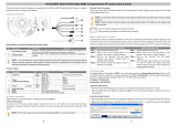
Camera’s Connectors (Indoor Only)
For network and PoE connections
Insert the microSD card into the card slot to store videos and snapshots. Do
not remove the microSD card when the camera is powered on.
Two-way audio transmission
Press the button with a proper tool for at least 20 seconds to restore the
system.
* Do NOT connect external power supply to the alarm I/O connector of the camera.
NOTE: It is not recommended to record with the microSD card for 24/7 continuously, as it may not be able to
support long term continuous data read/write. Please contact the manufacturer of the microSD card for
information regarding the reliability and the life expectancy.
NOTE: To purchase power adaptor, please contact the camera manufacturer for further information.
Camera Cabling
Please follow the instructions below for cable connections.
Power Connection
Please use a 12 VDC power adaptor and plug it to the camera and the power outlet. Alternatively, users can use an
Ethernet cable and connect it to the RJ-45 connector of the camera and a Power Sourcing Equipment (PSE) switch.
NOTE: If PoE is used, make sure PSE is in use in the network.
Ethernet Cable Connection
Connect one end of the Ethernet cable to the RJ-45 connector of the camera and plug the other end of the cable to
the network switch or PC.
NOTE: In some cases, Ethernet crossover cable might be needed when connecting the camera directly to the PC.
NOTE: Check the status of the link indicator and activity indicator LEDs. If the LEDs are unlit, please check
the LAN connection.
Green Link Light indicates good network connection.
Orange Activity Light flashes for network activity indication.
NOTE: The camera is to be connected only to PoE networks without routing to the outside plant or equivalent
location.
Function Cable (Outdoor Only)
Two-way audio transmission
Power (12 VDC)
(2-Pin Terminal
Block)
Alarm I/O
(4-Pin Terminal
Block)
For network and PoE connections
Refer to microSD Card Slot in Camera’s Connectors (Indoor Only)
section.
Refer to Default Button in Camera’s Connectors (Indoor Only) section.
Before Login to the Camera
For initial access, search for the camera using the Discovery Tool (DeviceSearch.exe), which can be found on Vicon’s
website, www.vicon-security.com on the Software Downloads page. A client program will be automatically installed to
the PC when connecting to the camera. Before logging in to the camera, ensure downloading the ActiveX control is
allowed by either changing the ActiveX controls and plug-ins or setting Internet’s security level to default. For further
details, please refer to the User’s manual on Vicon’s website, www.vicon-security.com, Documentation.
ActiveX Controls and Plug-ins Settings
Step 1: Start the Internet Explorer (IE).
Step 2: Select <Tools> from the main menu of the
browser. Then click on <Internet Options>.
Step 3: Click on the <Security> tab and select
<Internet>, and click on <Custom level> to
change ActiveX settings.
Step 4: Set “ActiveX controls and plug-ins” items to
<Prompt> or <Enable>.
Step 1: Start the Internet Explorer (IE).
Step 2: Select <Tools> from the main menu of the
browser. Then click on <Internet Options>.
Step 3: Click on the <Security> tab and select
<Internet>.
Step 4: Down the page, click <Default Level> and click
on <OK> to confirm the setting. Close the
browser window; open a new one later for
accessing the IP camera.