Page is loading ...

Instruction Manual
http://www.hannainst.com
These Instruments are in
Compliance with the CE Directives
A
L
A
R
M
L
I
N
E
S
E
T
E
C
S
E
T
p
H
pH
0
SE
C
O
N
D
S
m
S
2
.0 0
TIM
E
R
M
IN
U
TE
S
90
P
R
O
P
O
R
TIO
N
A
L S
ET
T
IN
G
S
4
0
S
E
C
O
N
D
S
pH
2.0
0
T
IM
E
R
M
IN
U
T
ES
90
P
R
O
P
O
R
T
IO
N
A
L S
E
TT
IN
G
S
1
S
LO
P
E C
A
L
A
LA
R
M
ON
OFF
0.5 1.5
S
E
T
F
E
R
T
m
S
O
FF
S
ET
S
L
O
P
E
A
LA
R
M
ON
OFF
0.5 1.5
S
E
T
AC
ID
ALA
HI 991
1
10
2
.5
5
7.5
1
10
2.5
5
7.5
ALA
p
H
5
EC
m
S
F
E
F
EE
2
3
AC
ID
A
LK
pH
0
1
2
0
1
2
m
S
A
L
A
R
M
Z
E
R
O
C
A
L
HI 9913 - HI 9923
HI 9935
Wall Mounted Dual
Conductivity/TDS &
pH Controllers

2
ISO 9000 Certified
Company since 1992
TABLE OF CONTENTSTABLE OF CONTENTS
TABLE OF CONTENTSTABLE OF CONTENTS
TABLE OF CONTENTS
Dear Customer,
Thank you for choosing a Hanna Product.
Please read this instruction manual carefully before using the instru-
ment. This manual will provide you with the necessary information for
a correct use of the instrument, as well as a more precise idea of its
versatility. If you need more technical information, do not hesitate to
e-mail us at [email protected].
These instruments are in compliance with the
directives
EN 50081-1, 50082-1 and 61010-1.
PRELIMINARY EXAMINATION........................................................3
GENERAL DESCRIPTION ................................................................3
MECHANICAL LAYOUTS.................................................................4
FUNCTIONAL DIAGRAM HI 9913..................................................6
FUNCTIONAL DIAGRAM HI 9923..................................................9
FUNCTIONAL DIAGRAM HI 9935................................................ 12
CONNECTIONS & WIRING ..........................................................14
NORMAL OPERATION & MEASUREMENT .....................................19
pH CALIBRATION.......................................................................20
CONDUCTIVITY/TDS CALIBRATION................................................ 21
ADJUSTMENT OF SETPOINT(S) ................................................... 23
PROPORTIONAL CONTROL.......................................................... 24
CONDUCTIVITY DEAD BAND (HI 9923)........................................ 26
OVERDOSAGE TIMERS ................................................................ 26
pH VALUES AT VARIOUS TEMPERATURES...................................27
pH ELECTRODE CONDITIONING & MAINTENANCE.........................28
CONDUCTIVITY/TDS PROBE CLEANING & MAINTENANCE............... 29
SUGGESTED INSTALLATIONS FOR pH ELECTRODE ........................30
SUGGESTED INSTALLATIONS FOR EC/TDS PROBE ........................31
ACCESSORIES .............................................................................33
WARRANTY ................................................................................34
CE DECLARATION OF CONFORMITY.............................................. 35

3
PRELIMINARY EXAMINATIONPRELIMINARY EXAMINATION
PRELIMINARY EXAMINATIONPRELIMINARY EXAMINATION
PRELIMINARY EXAMINATION
GENERAL DESCRIPTIONGENERAL DESCRIPTION
GENERAL DESCRIPTIONGENERAL DESCRIPTION
GENERAL DESCRIPTION
Remove the instrument from the packing material and examine it
carefully to make sure that no damage has occurred during ship-
ping. If there is any noticeable damage, notify your Dealer.
Note: Save all packing materials until you are sure that the
instrument functions correctly. Any defective item must be
returned in the original packaging together with the supplied
accessories.
IMPORTANT:
1. Read the instructions before using the instrument.
2. The instrument should be connected to a mains socket.
3. Never install the controller outdoors, in a wet or humid area or
under direct sun light. Nor install the controller where liquids
may be sprayed or poured on it.
4. The instrument’s main power line as well as the dosage and
alarm terminals are protected by separate 2A fuses. Use only 2A
fuses for replacement.
Hanna's wall-mounted conductivity/TDS and pH controllers
are
designed to meet a variety of process control requirements, especially
those in horticultural, hydroponics and agricultural applications on
the one hand and boilers and cooling towers on the other.
All controllers provide for two separate relays, one for pH and another
for Conductivity/TDS. HI 9913 and HI 9935 also come with propor-
tional control to save on use of chemicals and fertilizers.
All models operate with the optional Hanna 4-ring probes to provide
a linear and repeatable measurement. The conductivity/TDS probes
can be installed quickly and easily. Simply plug the DIN connector
into the socket and tighten the retainer ring.
The EC/TDS probes incorporate a temperature sensor and the control-
lers will automatically compensate for the temperature effect. Accurate
measurements are displayed on a large LCD.
Similarly, the pH electrode can be installed quickly and easily. Simply
plug the universal BNC connector into the socket and twist it into a
secured position. In order to avoid electrical noise and interference,
the pH circuitry also provides for a ground probe (differential input).

4
pH
0
1
2
0
1
2
mS
ALARM
pH
0
SECONDS
mS
2.0 0
TIMER
MINUTES
90
PROPORTIONAL SETTINGS
47
0
SECONDS
pH
2.0
0
TIMER
MINUTES
90
PROPORTIONAL SETTINGS
14
SLOPE CAL
ALARM
ON
OFF
0.5 1.5
SET
FERT
mS
OFFSET SLOPE
ALARM
ON
OFF
0.5 1.5
SET
ACID
ALARM
HI 9913
1
10
2.5
5
7.5
1
10
2.5
5
7.5
ALARM
pH
5
6
EC
mS
FEED
FEED
2
3
SET pH
SET EC
ALARM
LINE
ACID
ALK
LCD DISPLAY
CALIBRATION
TRIMMERS
CONTROL KNOBS
AND SWICHES
DOSING TERMINALS
POWER SUPPLY
TERMINALS
ALARM CONTACTS
MATCHING PIN
ZERO CAL
Fig. 2
Figure 2 illustrates the controls and terminals.
MECHANICAL LAYOUTSMECHANICAL LAYOUTS
MECHANICAL LAYOUTSMECHANICAL LAYOUTS
MECHANICAL LAYOUTS
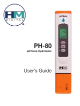
BNC CONNECTOR
MATCHING PIN FOR GROUND PROBE
DIN CONNECTOR
WIRING ACCESS
PORTS
Fig. 1
The controllers come equipped with relays operating at a maximum of
2A (240V).
They incorporate a triple contact alarm system. When activated, the
alarm contacts will open or close, triggering the mechanism of your
choice, whether a buzzer, light or any other electrical device.
The controllers are housed in a rugged, modular, fiber-reinforced ABS
housing.
All models can be wired to work with 110/115V or 220/240V at
50/60 Hz power supplies.
Figure 1 illustrates the connector for pH electrode, matching pin
connection, conductivity/TDS probe and the wiring access ports.

5
3.8“
96.9 mm
25 mm
1“
75 mm
3“
Fig. 3
227.8 mm
9“
188.6 mm
7.4“
221.8 mm
8.7“
174.8 mm
6.9“
Fig. 4
Figure 3 is a dimensioned, bottom view of the wall mounted
controller. The modular design isolates the control circuitry from the
contacts making it possible to make the connections and then close
the compartment. Adjustments can then be made only in the control
area, without having to open the contacts compartment.
Figure 4 is a dimensioned front view of the wall mounted controller.
The molded, mounting holes in the corners provide for quick and
secure installation. No additional hardware is needed for mounting.
All electrical connections and controls are located on the front of the
instrument so that adjustment can be made without having to
remove the unit.

6
FUNCTIONAL DIAGRAM HI 9913FUNCTIONAL DIAGRAM HI 9913
FUNCTIONAL DIAGRAM HI 9913FUNCTIONAL DIAGRAM HI 9913
FUNCTIONAL DIAGRAM HI 9913
pH
0
1
2
0
1
2
mS
ALARM
pH
0
SECONDS
mS
2.0 0
TIMER
MINUTES
90
PROPORTIONAL SETTINGS
47
0
SECONDS
pH
2.0
0
TIMER
MINUTES
90
PROPORTIONAL SETTINGS
14
SLOPE CAL
ALARM
ON
OFF
0.5 1.5
SET
FERT
mS
OFFSET SLOPE
ALARM
ON
OFF
0.5 1.5
SET
ACID
ALARM
HI 9913
1
10
2.5
5
7.5
1
10
2.5
5
7.5
ALARM
pH
5
6
EC
mS
FEED
FEED
2
3
SET pH
SET EC
ALARM
LINE
ACID
ALK
1
3
4
5
6
7
8
9
10
11
13
17
18
19
20
21
23
2
2
9
25
12
14
16
22
24
ZERO CAL
FRONT PANEL
Left panel
1. Alarm LED signal for pH
2. Liquid Crystal Display for pH and Conductivity (EC)
3. Acid feed LED and dial to adjust the pH setpoint
4. Selection switch for Acid or Alkaline dosage
5. Alarm disable switch for pH
6. Slope calibration trimmer for pH
7. Offset calibration trimmer for pH
8. Proportional pH band and time cycle settings
9. Two independent overdosage timers
10. Alarm LED signal for Conductivity (EC)
11. Fertilizer feed LED and dial to adjust the Conductivity setpoint
12. Zero calibration trimmer for Conductivity (EC)
13. Slope calibration trimmer for Conductivity (EC)
14. Proportional Conductivity band and time cycle settings
16. Alarm disable switch for Conductivity (EC)
Right panel
17. pH alarm setting from 0.0 to 2.0 pH
18. Short the terminals if a pH ground probe is not in use, or
connect the ground probe wire to the Matching Pin terminal
19. Conductivity alarm setting from 0 to 2.0 mS/cm (EC)

7
Unplug the instrument from the power supply before
wiring or replacing the fuses.
26
27
28
20. Triple contact alarm in a Normally Closed (NC) or a Normally
Open (NO) position.
21. Powered dosage terminals (Relay) for pH correction
22. Powered dosage terminals (Relay) for EC correction
23. 110/115V or 220/240V power configuration
24. Incoming power terminals
25. Fuses
BOTTOM VIEW
26. Female BNC connector for a combination pH electrode
27. 4-mm Banana socket for the pH ground probe
28. Female DIN connector for Conductivity probe

8
Specifications HI 9913
RANGE 0.00 to 14.00 pH and 0.00 to 10.00 mS/cm (EC)
RESOLUTION 0.01 pH and 0.01 mS/cm
ACCURACY ±0.02 pH and ±2% F. S.
(@20°C/68°F)
TYPICAL EMC ±0.1 pH and ±2% F. S.
DEVIATION
CALIBRATION
WEIGHT 1.6 Kg (3.5 lb.)
ENCLOSURE 181 x 221 x 142mm (7.1 x 8.7 x 5.6")
CASE MATERIAL Fiber-reinforced, self-extinguishing ABS
SETPOINT RANGE From 4.0 to 7.0 pH and 1.0 to 4.0 mS/cm (EC)
PROPORTIONAL
CONTROL
ALARM
CONTACT
POWER SUPPLY 220/240V or 110/115V at 50/60Hz
DOSING
TERMINALS
ENVIRONMENT -10 to 50°C (14 to 122°F)
max. 95% RH non-condensing
Through "OFFSET" and "SLOPE" trimmers for pH, and
“ZERO CAL” and “SLOPE CAL” for Conductivity (EC)
Two independent controls: pH from 0.0 to 2.0 and
Conductivity (EC) from 0.0 to 2.0 mS/cm with two
separate time cycles from 0 to 90 seconds
Terminals can be configured as normally open or
normally closed (isolated output Max. 2A, Max. 240V,
resistive load, 1,000,000 strokes). The alarm is
activated if pH falls below the setpoint by the user-
selectable interval (0.0 to 2.0 pH), or conductivity
exceeds the setpoint by more than the user-selectable
interval (0 to 2.0 mS/cm) or due to overdosage
Two sets of independent terminals (115 to 240V,
Max.2A, 1,000,000 strokes) are activated whenever
pH exceeds the pH setpoint and/or conductivity falls
below the EC setpoint
PROBE
Any combination pH electrode with a universal BNC
connector and Hanna Conductivity 4-ring
potentiometric probe with built-in temperature sensor
and DIN connector (optional)

9
FUNCTIONAL DIAGRAM HI 9923FUNCTIONAL DIAGRAM HI 9923
FUNCTIONAL DIAGRAM HI 9923FUNCTIONAL DIAGRAM HI 9923
FUNCTIONAL DIAGRAM HI 9923
pH
0
mS
0.50
m TIMER
S
MINUTES
510
pH
TIMER
MINUTES
1
6
SLOPE CAL
AUTO
MANUAL
SET
mS
OFFSET SLOPE
AUTO
MANUAL
SET
ALK
ALARM
HI 9923
1
90
45
1
90
45
ALARM
pH
mS
DEAD BAND
FEED
7.5
2
4
BLEED
3
5
SET pH
SET EC
ALARM
LINE
1
3
5
6
7
9
10
11
15
18
17
19
20
21
2
9
25
12
13
16
ZERO CAL
pH
0
1
2
0
1
2
mS
ALARM
22
23
24
FRONT PANEL
Left panel
1. Alarm LED signal for pH
2. Liquid Crystal Display for pH and Conductivity
3. Alkaline feed LED and dial to adjust the pH setpoint
5. Alarm disable switch for pH
6. Slope calibration trimmer for pH
7. Offset calibration trimmer for pH
9. Two independent overdosage timers
10. Alarm LED signal for Conductivity
11. Bleed LED and dial to adjust the Conductivity setpoint
12. Zero calibration trimmer for Conductivity
13. Slope calibration trimmer for Conductivity
15. Conductivity Dead Band setting
16. Alarm disable switch for Conductivity
Right panel
17. pH alarm setting from 0.0 to 2.0 pH
18. Short the terminals if a pH ground probe is not in use, or
connect the ground probe wire to the Matching Pin terminal
19. Conductivity alarm setting from 0 to 2.0 mS/cm
20. Triple contact alarm in a Normally Closed (NC) or a Normally
Open (NO) position.
21. Powered dosage terminals (Relay) for pH correction
22. Powered dosage terminals (Relay) for Conductivity correction

10
26
27
28
23. 110/115V or 220/240V power configuration
24. Incoming power terminals
25. Fuses
BOTTOM VIEW
26. Female BNC connector for a combination pH electrode
27. 4-mm Banana socket for the pH ground probe
28. Female DIN connector for conductivity probe
Unplug the instrument from the power supply before
wiring or replacing the fuses.

11
Specifications HI 9923
RANGE 0.00 to 14.00 pH and 0.00 to 10.00 mS/cm (mmho/cm)
RESOLUTION 0.01 pH and 0.01 mS/cm (mmho/cm)
ACCURACY ±0.02 pH and ±2% F. S.
(@20°C/68°F)
TYPICAL EMC ±0.1 pH and ±2% F. S.
DEVIATION
CALIBRATION
WEIGHT 1.6 Kg (3.5 lb.)
ENCLOSURE 181 x 221 x 142mm (7.1 x 8.7 x 5.6")
CASE MATERIAL Fiber-reinforced, self-extinguishing ABS
SETPOINT RANGE From 5.0 to 10.0 pH & 1.00 to 6.00 mS/cm (mmho/cm)
ALARM
CONTACT
POWER SUPPLY 220/240V or 110/115V at 50/60Hz
DOSING
TERMINALS
ENVIRONMENT -10 to 50°C (14 to 122°F)
max. 95% RH non-condensing
Through "OFFSET" and "SLOPE" trimmers for pH, and
“ZERO CAL” and “SLOPE CAL” for Conductivity
DEAD BAND From 0.0 to 0.5 mS/cm (mmho/cm)
Terminals can be configured as normally open or
normally closed (isolated output Max. 2A, Max. 240V,
resistive load, 1,000,000 strokes). The alarm is activated
if pH exceeds the setpoint by the user-selectable interval
(0 to 2 pH), or Conductivity falls below the setpoint by
more than the user-selectable interval (0 to 2.0 mS/
cm) or due to overdosage
Two sets of independent terminals (115 to 240V, Max.
2A, 1,000,000 strokes) are activated whenever pH falls
below the pH setpoint or the conductivity exceeds the
“BLEED” setpoint
PROBE
Any combination pH electrode with a universal BNC
connector and Hanna Conductivity 4-ring
potentiometric probe with built-in temperature sensor
and DIN connector (optional)

12
pH
0
SECONDS
ppm
400 0
TIMER
MINUTES
90
PROPORTIONAL SETTINGS
47
0
SECONDS
pH
2.0
0
TIMER
MINUTES
90
PROPORTIONAL SETTINGS
900 1800
SLOPE CAL
ALARM
ON
OFF
100 300
SET
FERT
ppm
OFFSET SLOPE
ALARM
ON
OFF
0.5 1.5
SET
ACID
ALARM
HI 9935
1
10
2.5
5
7.5
1
10
2.5
5
7.5
ALARM
pH
5
6
ppm
FEED
FEED
1200
1500
pH
0
1
2
0
200
400
ppm
ALARM
SET pH
SET EC
ALARM
LINE
ZERO CAL
1
3
5
6
7
8
9
10
11
13
17
18
19
20
21
23
2
2
9
25
12
14
16
22
24
TDS
FUNCTIONAL DIAGRAM HI 9935FUNCTIONAL DIAGRAM HI 9935
FUNCTIONAL DIAGRAM HI 9935FUNCTIONAL DIAGRAM HI 9935
FUNCTIONAL DIAGRAM HI 9935
FRONT PANEL
Left panel
1. Alarm LED signal for pH
2. Liquid Crystal Display for pH and TDS (ppm or mg/L)
3. Acid feed LED and dial to adjust the pH setpoint
5. Alarm disable switch for pH
6. Slope calibration trimmer for pH
7. Offset calibration trimmer for pH
8. Proportional pH band and time cycle settings
9. Two independent overdosage timers
10. Alarm LED signal for TDS
11. Fertilizer feed LED and dial to adjust the TDS setpoint
12. Zero calibration trimmer for TDS
13. Slope calibration trimmer for TDS
14. Proportional TDS band and time cycle settings
16. Alarm disable switch for TDS
Right panel
17. pH alarm setting from 0.0 to 2.0 pH
18. Short the terminals if a pH ground probe is not in use, or
connect the ground probe wire to the Matching Pin terminal
19. TDS alarm setting from 0 to 400 ppm (mg/L)
20. Triple contact alarm in a Normally Closed (NC) or a Normally
Open (NO) position.

13
21. Powered dosage terminals (Relay) for pH correction
22. Powered dosage terminals (Relay) for TDS correction
23. 110/115V or 220/240V power configuration
24. Incoming power terminals
25. Fuses
26
27
28
BOTTOM VEW
26. Female BNC connector for a combination pH electrode
27. 4-mm Banana socket for the pH ground probe
28. Female DIN connector for TDS probe
Unplug the instrument from the power supply before
wiring or replacing the fuses.

14
CONNECTIONS & WIRINGCONNECTIONS & WIRING
CONNECTIONS & WIRINGCONNECTIONS & WIRING
CONNECTIONS & WIRING
Specifications HI 9935
RANGE 0.00 to 14.00 pH and 0.00 to 1999 ppm (mg/L)
RESOLUTION 0.01 pH and 1 ppm (mg/L)
ACCURACY ±0.02 pH and ±2% F. S.
(@20°C/68°F)
TYPICAL EMC ±0.1 pH and ±2% F. S.
DEVIATION
CALIBRATION
WEIGHT 1.6 Kg (3.5 lb.)
ENCLOSURE 181 x 221 x 142mm (7.1 x 8.7 x 5.6")
CASE MATERIAL Fiber-reinforced, self-extinguishing ABS
SETPOINT RANGE From 4.0 to 7.0 pH and 900 to 1800 ppm (mg/L)
PROPORTIONAL
CONTROL
ALARM
CONTACT
POWER SUPPLY 220/240V or 110/115V at 50/60Hz
DOSING
TERMINALS
ENVIRONMENT -10 to 50°C (14 to 122°F)
max. 95% RH non-condensing
Through "OFFSET" and "SLOPE" trimmers for pH, and
“ZERO CAL” and “SLOPE CAL” for TDS
Two independent controls: pH from 0.0 to 2.0 and
TDS from 0.0 to 400 ppm (mg/L) with two separate
time cycles from 0 to 90 seconds
Terminals can be configured as normally open or
normally closed (isolated output Max. 2A, Max. 240V,
resistive load, 1,000,000 strokes). The alarm is
activated if pH falls below the setpoint by the user-
selectable interval (0 to 2 pH),or TDS exceeds the
setpoint by more than the user-selectable interval (0
to 400 ppm) or due to overdosage
TDS RATIO 0.65 ppm (mg/L) = 1 µS/cm
Two sets of independent terminals (115 to 240V, Max.
2A, 1,000,000 strokes) are activated whenever pH
exceeds the pH setpoint and for the TDS falls below
the TDS setpoint
PROBE
Any combination pH electrode with a universal BNC
connector and Hanna TDS 4-ring potentiometric probe
with built-in temperature sensor and DIN connector
(optional)
GENERAL POINTS
• The
relay terminals relay terminals
relay terminals relay terminals
relay terminals of the controller are
poweredpowered
poweredpowered
powered. This
means that you can simply hook up your pump or electrovalve
directly to the controller and do not need additional power
supply.

15
• Unscrew the 4 screws on the right hand panel and remove the
cover and the gasket. Thread the wires through the access ports
on the right hand side of the controllers.
•
BeforeBefore
BeforeBefore
Before
connecting the controller to the mains, wire connecting the controller to the mains, wire
connecting the controller to the mains, wire connecting the controller to the mains, wire
connecting the controller to the mains, wire
the controller completelythe controller completely
the controller completelythe controller completely
the controller completely and make all the connections for
pumps, valves, alarm, probe, set the alarm threshold and adjust
the settings. Upon completion
replace the coverreplace the cover
replace the coverreplace the cover
replace the cover. Only then
connect the controller to the power supply.
pH ELECTRODE & GROUND PROBE CONNECTIONS
• Simply attach any combination pH electrode with a male BNC
connector (such as HI 1002/3) to the female BNC socket located
on the bottom of the casing and twist it into a secure position.
• All controllers provide for a Ground Probe (differential input) to
reduce electrical noise and interference. The controller is shipped
with the Matching Pin and Reference terminals shorted (see 18 -
Functional Diagram). If you are not using a matching pin
(ground probe),
leave the terminals shortedleave the terminals shorted
leave the terminals shortedleave the terminals shorted
leave the terminals shorted
and skip the next two paragraphs.
• It is recommended that only electrodes that
incorporate a matching pin (such as HI 1003/3) are utilized. In
this case simply
attach the 4-mm banana connector ofattach the 4-mm banana connector of
attach the 4-mm banana connector ofattach the 4-mm banana connector of
attach the 4-mm banana connector of
the matchingthe matching
the matchingthe matching
the matching
pin to the socket pin to the socket
pin to the socket pin to the socket
pin to the socket located next to the BNC
connector on the outer casing (see 27 and 18 - Functional
Diagram) and
remove the jumpersremove the jumpers
remove the jumpersremove the jumpers
remove the jumpers shorting the matching
pin terminals.
• When using a separate probe for grounding purposes, wire it to
the Matching Pin terminals on the right hand panel and remove
the jumpers (see 18 - Functional Diagram).
BNC CONNECTOR
MATCHING PIN FOR GROUND PROBE
DIN CONNECTOR
WIRING ACCESS
PORTS
NOTE:
NEVER leave the jumper in when
using an electrode with a matching
pin. This can shorten the life of the
electrode (reference) drastically.
REMOVE WHEN
USING MATCHING PIN

16
CONDUCTIVITY/TDS PROBE CONNECTION
• Attach the conductivity/TDS probe (HI 3002, HI 3001D or
HI 7638) to the DIN socket located on the bottom of the casing.
Align the guide on the connector with the socket, push the
connector in and tighten the retainer ring. (HI 3002 is more
suitable for direct immersion in the tank, vat or pipes. HI 3001D
can be mounted directly into a pipe and HI 7638 is recom-
mended for high temperature and pressure applications).
• The probes incorporate a temperature sensor and the controller’s
circuitry automatically compensates for the temperature effect.
RELAY CONNECTIONS
• The controllers provide for two separate relays, one for pH and
another for Conductivity (or TDS).
• Wire the external devices (pumps or electrovalves) directly to the
relay terminal strips of the controller (see 21 and 22 - Functional
Diagram). The
terminals are poweredterminals are powered
terminals are poweredterminals are powered
terminals are powered and hence you
do do
do do
do
not need an external power supplynot need an external power supply
not need an external power supplynot need an external power supply
not need an external power supply for the pumps or
electrovalves.
• The relay for the pH is activated when pH exceeds the setpoint
(HI 9913 and HI 9935) or falls below the setpoint (HI 9923).
The relay for conductivity/TDS instead acts in the opposite direc-
tion, i.e. it is
activated when
the conductivity
(or TDS) falls be-
low the setpoint
(HI 9913 and
HI 9935) or ex-
ceeds the setpoint
(HI 9923).
ALARM CONNECTIONS
• The operator can select an alarm threshold of 0.0 to 2.0 pH by
turning the alarm knob (see 17 - Functional Diagram). If the pH
measurements fall below the setpoint (HI 9913 and HI 9935) or
are above the setpoint (HI 9923) by a margin greater than the
user-selectable alarm threshold, the alarm terminal is activated.
pH
0
1
2
0
1
2
mS
ALARM
pH
0
SECONDS
mS
2.0 0
TIMER
MINUTES
90
PROPORTIONAL SETTINGS
47
0
SECONDS
pH
2.0
0
TIMER
MINUTES
90
PROPORTIONAL SETTINGS
14
SLOPE CAL
ALARM
ON
OFF
0.5 1.5
SET
FERT
mS
OFFSET SLOPE
ALARM
ON
OFF
0.5 1.5
SET
ACID
ALARM
HI 9913
1
10
2.5
5
7.5
1
10
2.5
5
7.5
ALARM
pH
5
6
EC
mS
FEED
FEED
2
3
SET pH
SET EC
ALARM
LINE
ACID
ALK
ZERO CAL
BL DOSING
PUMPS

17
pH
0
1
2
0
1
2
mS
ALARM
pH
0
SECONDS
mS
2.0 0
TIMER
MINUTES
90
PROPORTIONAL SETTINGS
47
0
SECONDS
pH
2.0
0
TIMER
MINUTES
90
PROPORTIONAL SETTINGS
14
SLOPE CAL
ALARM
ON
OFF
0.5 1.5
SET
FERT
mS
OFFSET SLOPE
ALARM
ON
OFF
0.5 1.5
SET
ACID
ALARM
HI 9913
1
10
2.5
5
7.5
1
10
2.5
5
7.5
ALARM
pH
5
6
EC
mS
FEED
FEED
2
3
SET pH
SET EC
ALARM
LINE
ACID
ALK
ZERO CAL
EXTERNAL ELECTRICAL
DEVICE ACTIVATED BY
AN ALARM CONDITION
AUTO
MANUAL
pH
0
1
2
0
1
2
mS
ALARM
pH
0
1
2
0
200
400
ppm
ALARM
• The operator can similarly select an
alarm threshold of 0.0 to 2.0 mS/cm
(HI 9913 and HI 9923) or 0 to 400
ppm (HI 9935) by turning the alarm
knob (see 19 - Functional Diagram). If
the conductivity/TDS measurements ex-
ceed the setpoint (HI 9913 and HI
9935) or the conductivity falls below
the setpoint (HI 9923) by a margin greater than the user-
selectable alarm threshold, the alarm terminal is activated.
• The alarm can be selected as normally closed ("NC") by connecting
the external device to the C and NC terminals or normally open
("NO") by connecting the external device to the C and NO
terminals.
• When activated, the alarm contacts will open or close, triggering
the mechanism of your choice. When the
alarm is activatedalarm is activated
alarm is activatedalarm is activated
alarm is activated
all other terminals all other terminals
all other terminals all other terminals
all other terminals (such as dosing relay etc.)
areare
areare
are
disactivateddisactivated
disactivateddisactivated
disactivated. The alarm LED lights also come on.
• The alarm AUTO/MANUAL switches are only to
disable thedisable the
disable thedisable the
disable the
alarm terminalalarm terminal
alarm terminalalarm terminal
alarm terminal (e.g. the buzzer will not sound). However, all
other functions such as disactivation of the dosing relay remains
unvaried, i.e. the pump or electrovalve will cease to operate until
the alarm condition is alleviated.
• If the pH AUTO/MANUAL switch is in the MANUAL
position, the buzzer/light will not come on if the
pH value is out. The alarm will be sounded for
Conductivity/TDS anomalies, unless likewise, the
Conductivity/TDS switch is also in the manual
position.
• The controller provides for
automatic fail-safeautomatic fail-safe
automatic fail-safeautomatic fail-safe
automatic fail-safe secruity by
activating the alarm if there is a power failure, regardless of
whether the NC or NO configurations were chosen.

18
• The alarm is also activated if one or both of the independent
maximum dosage times are exceeded. The
maximum time that the relay contacts remain
active continuously (max. dosage time) can be
set from 1 to 10 minutes for HI 9913 and
HI 9935 and 1 to 90 minutes for HI 9923.
• Once in an alarm condition, the contact remains activated until
the switch is put in the manual position or the measurements
return to normal values.
TEMPERATURE COMPENSATION
Temperature affects conductivity and TDS measurements considerably
(approx. 2% per degree Celsius). You however do not need to worry
about having to compensate for this or go through complicated
calculations since all three probes recommended in this manual
(HI 7638, HI 3002 and HI 3001D) compensate for the temperature
effect automatically.
MAIN POWER SUPPLY CONNECTION
•
BeforeBefore
BeforeBefore
Before
connecting the unit to the mains connecting the unit to the mains
connecting the unit to the mains connecting the unit to the mains
connecting the unit to the mains, make sure
that the
controller is completely wiredcontroller is completely wired
controller is completely wiredcontroller is completely wired
controller is completely wired and that all
connections for pump, alarm, probe, etc. have been made.
• For 220-240V, short the L1 and N1 termi-
nals. Then wire the external power supply
to the three terminals as shown.
• For 110-115V, short the L and L1 termi-
nals and the N1 and Neutral. Then wire
the external power supply to the three
terminals as shown.
• Replace the cover with the gasket and
screw it tight with the 4 screws provided. Only then connect the
controller to the mains.
ALARM DOSING TIME
MINUTES
1
10
2.5
5
7.5
Neutral
Line
POWER
SUPPLY
220 VAC
Configuration
L
L1
N1
Neutral
Line
POWER
SUPPLY
L
L1
N1
110 VAC
Configuration
110 VAC
Configuration

19
NORMAL OPERATION &NORMAL OPERATION &
NORMAL OPERATION &NORMAL OPERATION &
NORMAL OPERATION &
MEASUREMENTMEASUREMENT
MEASUREMENTMEASUREMENT
MEASUREMENT
Make sure that the controller has been properly calibrated before
commencing and that the pH and conductivity/TDS setpoints have
been adjusted (see following pages).
The pH electrode, conductivity/TDS probe and any ground probe
must be properly connected and wired to the controller (see preceding
pages).
The conductivity/TDS probe’s protective sleeve must not be removed
and the holes on the sleeve should be near the top (the cable end).
The probe must be immersed in the solution above the air-vent holes
on the external sleeve. The probe must be installed in such a way as
to minimize presence of air bubbles (see probe installation tips at the
end of the manual).
Remove the protective cap if it is still on the tip of the pH electrode
and ensure that the electrode is immersed in the solution (at least
4cm/1.5”). The electrode should be installed in such a away that it
permanently lies in the solution whether in a well, tank or on the
discharge pipe.
The controller provides for visual dosing status through two LED’s (see
3 and 11 - Functional Dia-
gram). The LED’s light up when
the controller is in the pH and/
or conductivity/TDS dosage
mode and the relays are acti-
vated.
The actual pH and conductivity or TDS values are displayed on the
two LCD’s in pH and mS/cm or ppm, respectively.
47
14
SET
FERT
SET
ACID
5
6
FEED
FEED
2
3
pH
5.80
mS
EC
1.60

20
pH pH
pH pH
pH
CALIBRATIONCALIBRATION
CALIBRATIONCALIBRATION
CALIBRATION
Make sure that the pH electrode and any ground probe have been
properly connected and wired to the controller (see preceding pages)
and that the meter is plugged to the mains.
Calibration should be performed at a temperature similar to that of
the liquid to be monitored.
Use a Checktemp (or an accurate thermometer)
as reference.
Remove the electrode cap if it is still on the
electrode.
During calibration, move the electrode and the
separate ground probe (if in use) together from
one buffer to the next.
If no separate ground probe is being used, make
sure that the Reference and the Matching Pin
terminals are shorted (see 18 - Functional Dia-
gram).
If the electrode (such as HI 1003/3) incorporates a ground probe
(matching pin) then remove the jumper.
OFFSET ADJUSTMENT:
• Rinse the tip of the electrode with pH 7.01
solution (HI 7007), then dip the bottom 4 cm
(1.5”) of the electrode (and ground probe) in
the pH 7.01 buffer.
• Place the Checktemp thermometer in the buffer solution.
• Wait for the measurement to stabilize and then adjust the
"OFFSET" trimmer (see 7 - Functional Diagram) to display 7.01
on the LCD if the temperature of the buffer solution is at 25°C
(77°F).
4cm
(1½")
HI 7007
4cm
(1½")
HI 7007
pH
OFFSET SLOPE
ALARM
ON
OFF
7.01
4cm
(1½")
HI 7007
/