
USER’S MANUAL
Revision 1.2a
®
SUPER
H8DGi
H8DGi-F
H8DG6
H8DG6-F

The information in this User’s Manual has been carefully reviewed and is believed to be accurate.
The vendor assumes no responsibility for any inaccuracies that may be contained in this document,
and makes no commitment to update or to keep current the information in this manual, or to notify
any person or organization of the updates. Please Note: For the most up-to-date version of this
manual, please see our web site at
www.supermicro.com.
Super Micro Computer, Inc. ("Supermicro") reserves the right to make changes to the product
described in this manual at any time and without notice. This product, including software and
documentation, is the property of Supermicro and/or its licensors, and is supplied only under a
license. Any use or reproduction of this product is not allowed, except as expressly permitted by
the terms of said license.
IN NO EVENT WILL Super Micro Computer, Inc. BE LIABLE FOR DIRECT, INDIRECT, SPECIAL,
INCIDENTAL, SPECULATIVE OR CONSEQUENTIAL DAMAGES ARISING FROM THE USE
OR INABILITY TO USE THIS PRODUCT OR DOCUMENTATION, EVEN IF ADVISED OF THE
POSSIBILITY OF SUCH DAMAGES. IN PARTICULAR, SUPER MICRO COMPUTER, INC. SHALL
NOT HAVE LIABILITY FOR ANY HARDWARE, SOFTWARE, OR DATA STORED OR USED
WITH THE PRODUCT, INCLUDING THE COSTS OF REPAIRING, REPLACING, INTEGRATING,
INSTALLING OR RECOVERING SUCH HARDWARE, SOFTWARE, OR DATA.
Any disputes arising between manufacturer and customer shall be governed by the laws of Santa
Clara County in the State of California, USA. The State of California, County of Santa Clara shall be
the exclusive venue for the resolution of any such disputes. Supermicro's total liability for all claims
will not exceed the price paid for the hardware product.
FCC Statement: Refer to Supermicro's web site for FCC Compliance Information.
California Best Management Practices Regulations for Perchlorate Materials: This Perchlorate
warning applies only to products containing CR (Manganese Dioxide) Lithium coin cells. “Perchlorate
Material-special handling may apply. See
www.dtsc.ca.gov/hazardouswaste/perchlorate”.
WARNING: Handling of lead solder materials used in this
product may expose you to lead, a chemical known to
the State of California to cause birth defects and other
reproductive harm.
Manual Revision 1.2a
Release Date: December 17, 2013
Unless you request and receive written permission from Super Micro Computer, Inc., you may not
copy any part of this document.
Information in this document is subject to change without notice. Other products and companies
referred to herein are trademarks or registered trademarks of their respective companies or mark
holders.
Copyright © 2013 by Super Micro Computer, Inc.
All rights reserved.
Printed in the United States of America

Preface
iii
Preface
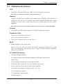
About This Manual
This manual is written for system integrators, PC technicians and knowledgeable
PC users. It provides information for the installation and use of the H8DG6/i(-F)
serverboard.
The H8DG6/i(-F) serverboard is based on the AMD® Dual SR5690 and one SP5100
chipset and supports two AMD Socket G34 type processor with up to 128 GB of
ECC/Non-ECC UDIMM or 512 GB of ECC RDIMM. This board series includes the
following serverboards and characteristics:
Serverboard Embeded IPMI Onboard SAS2
H8DG6 Yes
H8DGi
H8DG6-F Yes Yes
H8DGi-F Yes
Please refer to the motherboard specifi cations pages on our web site for updates on
supported processors (http://www.supermicro.com/aplus/). This product is intended
to be professionally installed.
Manual Organization
Chapter 1 includes a checklist of what should be included in your motherboard
box, describes the features, specifi cations and performance of the motherboard
and provides detailed information about the chipset.
Chapter 2 begins with instructions on handling static-sensitive devices. Read this
chapter when installing the processor(s) and memory modules and when installing
the motherboard in a chassis. Also refer to this chapter to connect the hard disk
drives, the various ports, and the power and reset buttons and the system LEDs.
If you encounter any problems, see Chapter 3, which describes troubleshooting
procedures for the video, the memory and the setup confi guration stored in CMOS.
For quick reference, a general FAQ (Frequently Asked Questions) section is
provided. Instructions are also included for contacting technical support. In addition,
you can visit our web site for more detailed information.
Chapter 4 includes an introduction to BIOS and provides detailed information on
running the CMOS Setup utility.
Appendix A provides BIOS Error Beep Code Messages.
Appendix B lists BIOS POST Checkpoint Codes.

iv
H8DG6/i(-F) SERVERBOARD USER'S MANUAL
Notes

v
Standardized Warning Statements
Standardized Warning Statements
About Standardized Warning Statements
The following statements are industry standard warnings, provided to warn the user
of situations which have the potential for bodily injury. Should you have questions
or experience diffi culty, Contact Supermicro's Technical Support department
for assistance. Only certifi ed technicians should attempt to install or confi gure
components.
Read this appendix in its entirety before installing or confi guring components in the
Supermicro chassis.
These warnings may also be found on our web site at http://www.supermicro.
com/about/policies/safety_information.cfm.
Battery Handling
Warning!
There is a danger of explosion if the battery is replaced incorrectly. Replace the
battery only with the same or equivalent type recommended by the manufacturer.
Dispose of used batteries according to the manufacturer's instructions
警告
电池更换不当会有爆炸危险。请只使用同类电池或制造商推荐的功能相当的电池更
换原有电池。请按制造商的说明处理废旧电池。
警告
電池更換不當會有爆炸危險。請使用製造商建議之相同或功能相當的電池更換原有
電池。請按照製造商的說明指示處理廢棄舊電池。
Warnung
Bei Einsetzen einer falschen Batterie besteht Explosionsgefahr. Ersetzen Sie die
Batterie nur durch den gleichen oder vom Hersteller empfohlenen Batterietyp.
Entsorgen Sie die benutzten Batterien nach den Anweisungen des Herstellers.

vi
H8DG6/i(-F) SERVERBOARD USER'S MANUAL
Attention
Danger d'explosion si la pile n'est pas remplacée correctement. Ne la remplacer
que par une pile de type semblable ou équivalent, recommandée par le fabricant.
Jeter les piles usagées conformément aux instructions du fabricant.
!הרהזא
תנכס תמייקץוציפ .הניקת אל ךרדב הפלחוהו הדימב הללוסה לש ףילחהל שי
גוסב הללוסה תא מ םאותה תרבחלמומ ןרציתצ.
תוללוסה קוליס תושמושמה עצבל שי .ןרציה תוארוה יפל
ﺮﻄﺧ ﻙﺎﻨﻫ ﻦﻣ ﻝﺍﺪﺒﺘﺳﺍ ﺔﻟﺎﺣ ﻲﻓ ﺭﺎﺠﻔﻧﺍ ﺔﻳﺭﺎﻄﺒﻟﺍ ﺔﺤﻴﺤﺻ ﺮﻴﻏ ﺔﻘﻳﺮﻄﺑ ﻚﻴﻠﻌﻓ
ﺔﻳﺭﺎﻄﺒﻟﺍ ﻝﺍﺪﺒﺘﺳﺍ
ﻂﻘﻓ ﻉﻮﻨﻟﺍ ﺲﻔﻨﺑ ﺎﻬﻟﺩﺎﻌﻳ ﺎﻣ ﻭﺃ ﺎﻤﻛﺖﺻﻭﺃ ﺔﻌﻨﺼﻤﻟﺍ ﺔﻛﺮﺸﻟﺍ ﻪﺑ
ﺕﺎﻳﺭﺎﻄﺒﻟﺍ ﻦﻣ ﺺﻠﺨﺗ ﻟ ﺎﻘﻓﻭ ﺔﻠﻤﻌﺘﺴﻤﻟﺍﺔﻌﻧﺎﺼﻟﺍ ﺔﻛﺮﺸﻟﺍ ﺕﺎﻤﻴﻠﻌﺘ
Waarschuwing
Er is ontploffi ngsgevaar indien de batterij verkeerd vervangen wordt. Vervang de
batterij slechts met hetzelfde of een equivalent type die door de fabrikant aanbevolen
wordt. Gebruikte batterijen dienen overeenkomstig fabrieksvoorschriften afgevoerd
te worden.
¡Advertencia!
Existe peligro de explosión si la batería se reemplaza de manera incorrecta.
Reemplazar la batería exclusivamente con el mismo tipo o el equivalente
recomendado por el fabricante. Desechar las baterías gastadas según las
instrucciones del fabricante.

Standardized Warning Statements
vii
Product Disposal
Warning!
Ultimate disposal of this product should be handled according to all national laws
and regulations.
警告
本产品的废弃处理应根据所有国家的法律和规章进行。
警告
本產品的廢棄處理應根據所有國家的法律和規章進行。
Warnung
Die Entsorgung dieses Produkts sollte gemäß allen Bestimmungen und Gesetzen
des Landes erfolgen.
¡Advertencia!
Al deshacerse por completo de este producto debe seguir todas las leyes y
reglamentos nacionales.
Attention
La mise au rebut ou le recyclage de ce produit sont généralement soumis à des
lois et/ou directives de respect de l'environnement. Renseignez-vous auprès de
l'organisme compétent.
רצומה קוליס
!הרהזא
ו תויחנהל םאתהב תויהל בייח הז רצומ לש יפוס קוליס.הנידמה יקוח
Waarschuwing
De uiteindelijke verwijdering van dit product dient te geschieden in overeenstemming
met alle nationale wetten en reglementen.
ﻲﺋﺎﻬﻨﻟﺍ ﺺﻠﺨﺘﻟﺍ ﻦﻣ ﺞﺘﻨﻤﻟﺍ ﺍﺬﻫ ﻪﻌﻣ ﻞﻣﺎﻌﺘﻟﺍ ﻲﻐﺒﻨﻳ ﻟ ﺎﻘﻓﻭ ﻊﻴﻤﺠﺔﻴﻨﻁﻮﻟﺍ ﺢﺋﺍﻮﻠﻟﺍﻭ ﻦﻴﻧﺍﻮﻘﻟﺍ ﺪﻨﻋ

viii
H8DG6/i(-F) SERVERBOARD USER'S MANUAL
Notes

ix
Table of Contents
Chapter 1 Introduction
1-1 Overview ......................................................................................................... 1-1
Checklist ..........................................................................................................1-1
1-2 Contacting Supermicro .................................................................................... 1-2
H8DG6/i(-F) Quick Reference ......................................................................... 1-5
1-3 Motherboard Features ..................................................................................... 1-7
1-4 Chipset Overview ..........................................................................................1-10
AMD SR5690/SP5100 Chipset .....................................................................1-10
HyperTransport Technology .......................................................................... 1-10
1-5 PC Health Monitoring .................................................................................... 1-10
1-6 Power Confi guration Settings.........................................................................1-11
1-7 Power Supply ................................................................................................1-12
1-8 Super I/O .......................................................................................................1-13
Chapter 2 Installation
2-1 Static-Sensitive Devices .................................................................................. 2-1
Precautions ..................................................................................................... 2-1
Unpacking ....................................................................................................... 2-1
2-2 Processor and Heatsink Installation................................................................ 2-2
2-3 Mounting the Motherboard into a Chassis ......................................................2-4
2-4 Installing Memory ............................................................................................2-4
DIMM Module Population Confi guration ....................................................2-6
2-5 PCI Expansion Cards ......................................................................................2-7
2-6 I/O Port and Control Panel Connections ........................................................ 2-8
Front Control Panel .........................................................................................2-8
2-7 Connector Defi nitions ..................................................................................... 2-9
2-8 Jumper Settings ............................................................................................2-16
Explanation of Jumpers ................................................................................ 2-16
2-9 Onboard Indicators ........................................................................................ 2-19
2-10 SAS and SATA Drive Connections ............................................................... 2-21
2-11 Enabling SATA RAID ..................................................................................... 2-22
Serial ATA (SATA)..........................................................................................2-22
Installing the OS/SATA Driver ....................................................................... 2-22
Building a Driver Diskette ......................................................................... 2-22
Enabling SATA RAID in the BIOS ................................................................. 2-23
Using the Adaptec RAID Utility .....................................................................2-24
Installing the RAID Driver During OS Installation .........................................2-24
Table of Contents

x
2-12 Installing Drivers ............................................................................................2-25
Supero Doctor III ...........................................................................................2-26
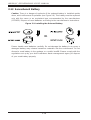
2-13 Serverboard Battery ...................................................................................... 2-28
Chapter 3 Troubleshooting
3-1 Troubleshooting Procedures ........................................................................... 3-1
Before Power On ............................................................................................ 3-1
No Power ........................................................................................................3-1
No Video .........................................................................................................3-2
Memory Errors ...............................................................................................3-2
Losing the System’s Setup Confi guration ....................................................... 3-2
3-2 Technical Support Procedures ........................................................................3-2
3-3 Frequently Asked Questions ........................................................................... 3-3
3-4 Returning Merchandise for Service................................................................. 3-4
Chapter 4 BIOS
4-1 Introduction ......................................................................................................4-1
4-2 Main Menu ...................................................................................................... 4-2
4-3 Advanced Settings Menu ................................................................................4-2
4-3 Security Menu ...............................................................................................4-15
4-4 Boot Menu ..................................................................................................... 4-16
4-5 Exit Menu ......................................................................................................4-17
Appendix A BIOS Error Beep Codes
Appendix B BIOS POST Checkpoint Codes
B-1 Uncompressed Initialization Codes .................................................................B-1
B-2 Bootblock Recovery Codes .............................................................................B-2
B-3 Uncompressed Initialization Codes .................................................................B-3
H8DG6/i(-F) SERVERBOARD USER'S MANUAL

Chapter 1: Introduction
1-1
Chapter 1
Introduction
1-1 Overview
Checklist
Congratulations on purchasing your computer motherboard from an acknowledged
leader in the industry. Supermicro boards are designed with the utmost attention to
detail to provide you with the highest standards in quality and performance.
Please check that the following items have all been included with your motherboard.
If anything listed here is damaged or missing, contact your retailer.
• One (1) H8DG6/i(-F) serverboard
• One (1) I/O shield (MCP-260-00027-0N)
• One (1) 9-pin serial port cable (CBL-0010L)
• One (1) 15.7-inch USB 2.0 2-Port with Key cable (CBL-0083L)
• Two (2) 50-cm I-Pass to four SATA PBF cables (CBL-0097L-02) (for H8DG6
and H8DG6-F only)
• Four (4) 2ft. Amphenol, SATA cable (CBL-0044L) (Six for H8DGi or H8DGi-F)
Note: For your system to work properly, please follow the links below to download
all necessary drivers/utilities and the user’s manual for your motherboard.
• Supermicro product manuals: http://www.supermicro.com/support/manuals/
• Product drivers and utilities: ftp://ftp.supermicro.com
• Product safety information:
http://super-dev/about/policies/safety_information.cfm
• If you have any questions, please contact our support team at:
support@supermicor.com

1-2
H8DG6/i(-F) SERVERBOARD USER'S MANUAL
1-2 Contacting Supermicro
Headquarters
Address: Super Micro Computer, Inc.
980 Rock Ave.
San Jose, CA 95131 U.S.A.
Tel: +1 (408) 503-8000
Fax: +1 (408) 503-8008
Email: [email protected] (General Information)
[email protected] (Technical Support)
Web Site:
www.supermicro.com
Europe
Address: Super Micro Computer B.V.
Het Sterrenbeeld 28, 5215 ML
's-Hertogenbosch, The Netherlands
Tel: +31 (0) 73-6400390
Fax: +31 (0) 73-6416525
Email: [email protected] (General Information)
[email protected] (Technical Support)
[email protected] (Customer Support)
Web Site:
www.supermicro.com
Asia-Pacifi c
Address: Super Micro Computer, Inc.
3F, No. 150, Jian 1st Rd.
Zhonghe Dist., New Taipei City 235
Taiwan (R.O.C)
Tel: +886-(2) 8226-3990
Fax: +886-(2) 8226-3992
Email: [email protected]
Tel: +886-(2)-8226-3990
Web Site:
www.supermicro.com.tw

Chapter 1: Introduction
1-3
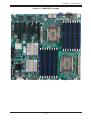
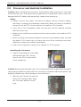
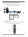
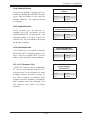
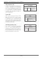
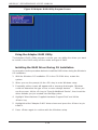
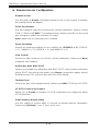
Figure 1-1. H8DG6/i(-F) Image

1-4
H8DG6/i(-F) SERVERBOARD USER'S MANUAL
Notes:
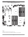
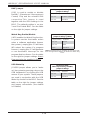
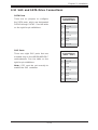
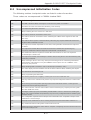
Jumpers not indicated are for test purposes only.
Not all ports, jumpers or LED Indicators are available on all serverboards.
Figure 1-2. H8DG6/i(-F) Motherboard Layout
(not drawn to scale)
LE1
BATTERY
JOH1
JI2C2
JI2C1
JPL1
JPG1
JWD1
JPS1
JPB1
DP3
LEDS1
DP1
JBT1
JIBTN1
T-SGPIO2T-SGPIO1
JWOL1
1
JSMB1
JTPM1
JWF1
JD1
JF1
FAN4
FAN3
FAN2
FAN5
FAN7/CPU1
FAN1
FAN6
FAN8/CPU2
JPI2C1
SAS 4~7
JPW1 JPW3 JPW2
BMC
Windbond
COM1
SLOT6 PCI-E 2.0 X16
SLOT5 PCI-E 2.0 X4 (IN X8)
COM2
USB7USB6
USB2/3
USB4/5
SATA0
SATA1
SATA2
SATA3
SATA4
SATA5
KB/MOUSE
USB0/1
IPMI_LAN
LAN1
LAN2
CPU1
CPU2
P2-DIMM1A
P2-DIMM1B
P2-DIMM2A
P2-DIMM2B
P2-DIMM3A
P2-DIMM3B
P2-DIMM4A
P2-DIMM4B
P1-DIMM4B
P1-DIMM4A
P1-DIMM3B
P1-DIMM3A
P1-DIMM2B
P1-DIMM2A
P1-DIMM1B
P1-DIMM1A
UID
SLOT2 PCI-E 2.0 X16
SLOT1 PCI-E 2.0 X4 (IN X8)
SLOT4 PCI-E 2.0 X16
SLOT3 PCI-E 2.0 X8
VGA
AMD
SP5100
AMD
SR5690
AMD
SR5690
LSI
2008
SAS2
INTEL
82576
SAS 0~3
JL1

Chapter 1: Introduction
1-5
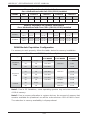
H8DG6/i(-F) Quick Reference
Jumper Description Default Setting
JBT1 CMOS Clear (See Section 2-7)
JI2C1/JI2C2 I2C to PCI-E Slot Enable/Disable Both Open (Disabled)
JPB1 BMC Enable/Disable Pins 1-2 (Enabled)
JPG1 VGA Enable/Disable Pins 1-2 (Enabled)
JPL1 LAN 1 Enable/Disable Pins 1-2 (Enabled)
JPS1 SAS Controller Enable/Disable Pins 1-2 (Enabled)
JWD1 Watch Dog Pins 1-2 (Reset)
LED Description
LAN Ports LEDs for the LAN Ethernet ports
Dedicated IPMI LAN LEDs for the dedicated IPMI LAN Ethernet port (H8DGi/6-F only)
DP1 LED for BMC Heartbeat
DP3 LED for Serverboard Power-On
LE1 LED for UID Button
LEDS1 SAS2008 Heartbeat LED

1-6
H8DG6/i(-F) SERVERBOARD USER'S MANUAL
Connector Description
COM1/COM2 COM1 Serial Port/Header
FAN 1-8 Chassis/CPU Fan Headers
IPMI LAN Dedicated IPMI LAN Port (H8DGi/6-F only)
JD1 Speaker Header
JF1 Front Panel Connector
JIBTN1 RAIDKey for RAID 5 SAS support (optional for H8DG6(-F) only)
JL1 Chassis Intruder Header
JOH1 Overheat Warning Header
JPI2C1 Power I
2
C Header
JPW1 24-pin Main ATX Power Connector
JPW2/3 +12V 8-pin CPU Power Connectors
JTPM1 Trusted Platform Module Header
JSMB1 System Management Bus Header (SMBus)
JWF1 SATA DOM (Disk_On_Module) PWR
JWOL1 Wake-On-LAN Header
LAN1/2 Gigabit Ethernet (RJ45) Ports
PS2 Mouse/Keyboard PS2 Mouse/Keyboard connectors
SAS0~3, SAS4~7 SAS Ports (H8DG6(-F) only)
SATA0 ~ SATA5 SATA Ports
T-SGPIO1/T-SGPIO2 Serial General Purpose Input/Output Header for SATA
USB0/1, USB2/3, USB4/5, USB6/7 Universal Serial Bus (USB) Ports, Headers and Type-A Ports
VGA VGA Connector

Chapter 1: Introduction
1-7
1-3 Motherboard Features
CPU
• Dual AMD Opteron 6000 series (AMD Socket G34 type) processor
Note: Refer to our web site for details on supported processors.
Memory
• Sixteen (16) four channel DIMM slots support up to 128 GB of ECC/Non-ECC
UDIMM or 512 GB of ECC RDIMM, with DDR3-1600/1333/1066 Mhz speed
SDRAM in 1 GB, 2 GB, 4 GB, 8 GB, 16 GB or 32 GB sizes of 1.5V or 1.35V
voltages.
Note: Refer to Section 2-4 before installing memory and our web site for recommended DIMMs.
Chipset
• Dual AMD SR5690 chipsets and one SP5100 Southbridge chipset
Expansion Slots
• Three (3) PCI-Express x16 Gen. 2
• One (1) PCI-Express x8 Gen. 2
• Two (2) PCI-Express x4 (in x8 slot) Gen. 2
BIOS
• 16 Mb AMIBIOS
®
SPI Flash ROM
• DMI 2.3, PCI 2.2, ACPI 1.0 (ACPI 2.0 is BIOS supported), SMBIOS 2.3, Real
Time Clock Wakeup, Plug and Play (PnP), BIOS resume hot keys, Hardware
BIOS Virus Protection
PC Health Monitoring
• Onboard voltage monitors
• Fan status monitor with fi rmware/software on/off and speed control
• Watch Dog
• Environmental temperature monitoring via BIOS
• Power-up mode control for recovery from AC power loss
• System resource alert (via included utility program)
• Auto-switching voltage regulator for the CPU core
• CPU thermal trip support
• I
2
C temperature sensing logic
• Chipkill Support

1-8
H8DG6/i(-F) SERVERBOARD USER'S MANUAL
ACPI Features
• Microsoft OnNow
• Slow blinking LED for suspend state indicator
• BIOS support for USB keyboard
• Wake-On-LAN (WOL)
Onboard I/O
• Six (6) SATA ports supported by an on-chip SATA controller (RAID 0, 1 and 10
supported)
• Eight (8) SAS ports supported by an SAS2008 SAS2 controller (RAID 0, 1 and 10
supported; Raid 5 Optional) (H8DG6 and H8DG6-F only)
• Eight (8) USB (Universal Serial Bus 2.0) ports (2x rear, 2x headers (USB 2/3
and USB 4/5), 2x type A)
• Two (2) LAN ports supported by one onboard Intel® 82576 Ethernet controllers
for 10/100/1000Base-T
• One (1) dedicated IPMI LAN port (H8DG6/i-F only)
• One (1) VGA port supported by an onboard Matrox
®
G200 graphics controller
(with 16 MB DDR2 memory)
• Two COM Ports (one external serial port, one Fast UART 16550 port)
Other
• Onboard power LED
• Chassis intrusion detection
CD Utilities
• BIOS fl ash upgrade utility
• Super Doctor III
• IPMI 1.5 / 2.0
Dimensions
• Extended-ATX form: (LxW) 12" x 13" (305 x 330 mm)

Chapter 1: Introduction
1-9
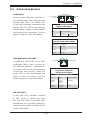
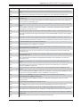
8x DIMM
LPC BUS
KEYBOARD/
MOUSE
8x DIMM
FWH
G34-SOCKET #2
LPC SIO
W83627DHG-P
AMD
SR5690#1
PCIE (X16)
PCIE (X8)
H/W_MONITOR
W83795
FAN
CONN. (8)
SATA PORT X6
SATA
SLOT#1
PCIE_(X4)
VRM
VRM
SLOT#6
PCIE_(X16)
HT Link
16/16-2.6GHz
SLOT#4
PCIE_(X16)
SLOT#3
PCIE_(X8)
HT Link
16 x16
b
it
s 6.4GHz
USB
USB PORT X8
LSI
SAS2 2008
PCIE (X8)
LAN
Intel 82576
PCIE (x4)
AMD
SP5100
Winbond
WPCM450
VGA
HT Link
AMD
SR5690#2
16/16-2.6GHz
DDR3
1600/1333/1066
PCIE (X4)
SLOT#5
PCIE_(X4)
G34-SOCKET #1
SLOT#2
PCIE_(X16)
DDR3
1600/1333/1066
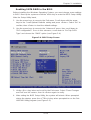
Figure 1-3. AMD Dual SR5690 and one SP5100 Chipset:
System Block Diagram
Note: This is a general block diagram and may not exactly represent
the features on your motherboard. See the previous pages for the
actual specifi cations of your motherboard.

1-10
H8DG6/i(-F) SERVERBOARD USER'S MANUAL
1-4 Chipset Overview
The H8DG6/i(-F) serverboard is based on the AMD Dual SR5690 and one SP5100
chipset. This chipset functions as a Media and Communications Processor (MCP).
Controllers for the system memory are integrated directly into AMD Opteron
processors.
AMD SR5690/SP5100 Chipset
The AMD Dual SR5690 and one SP5100 are each a single-chip, high-performance
HyperTransport peripheral controller. It includes a 42-lane PCI Express interface, an
AMD Opteron 16-bit Hyper Transport interface link, a six-port Serial ATA interface
and an eight-port USB 2.0 interface. This hub connects directly to the CPU.
HyperTransport Technology
HyperTransport technology is a high-speed, low latency point to point link that was
designed to increase the communication speed by a factor of up to 48x between
integrated circuits. This is done partly by reducing the number of buses in the
chipset to reduce bottlenecks and by enabling a more effi cient use of memory
in multi-processor systems. The end result is a signifi cant increase in bandwidth
within the chipset.
1-5 PC Health Monitoring
This section describes the PC health monitoring features of the H8DG6/i(-F)
serverboard. The serverboard has an onboard System Hardware Monitor chip that
supports PC health monitoring.
Onboard Voltage Monitors
The onboard voltage monitor will continuously scan crucial voltage levels. Once
a voltage becomes unstable, it will give a warning or send an error message to
the screen. Users can adjust the voltage thresholds to defi ne the sensitivity of the
voltage monitor. Real time readings of these voltage levels are all displayed in BIOS.
Fan Status Monitor with Firmware/Software Speed Control
The PC health monitor can check the RPM status of the cooling fans. The onboard
fans are controlled by thermal management via BIOS.
Page is loading ...
Page is loading ...
Page is loading ...
Page is loading ...
Page is loading ...
Page is loading ...
Page is loading ...
Page is loading ...
Page is loading ...
Page is loading ...
Page is loading ...
Page is loading ...
Page is loading ...
Page is loading ...
Page is loading ...
Page is loading ...
Page is loading ...
Page is loading ...
Page is loading ...
Page is loading ...
Page is loading ...
Page is loading ...
Page is loading ...
Page is loading ...
Page is loading ...
Page is loading ...
Page is loading ...
Page is loading ...
Page is loading ...
Page is loading ...
Page is loading ...
Page is loading ...
Page is loading ...
Page is loading ...
Page is loading ...
Page is loading ...
Page is loading ...
Page is loading ...
Page is loading ...
Page is loading ...
Page is loading ...
Page is loading ...
Page is loading ...
Page is loading ...
Page is loading ...
Page is loading ...
Page is loading ...
Page is loading ...
Page is loading ...
Page is loading ...
Page is loading ...
Page is loading ...
Page is loading ...
Page is loading ...
Page is loading ...
Page is loading ...
Page is loading ...
Page is loading ...
Page is loading ...
Page is loading ...
Page is loading ...
Page is loading ...
-
 1
1
-
 2
2
-
 3
3
-
 4
4
-
 5
5
-
 6
6
-
 7
7
-
 8
8
-
 9
9
-
 10
10
-
 11
11
-
 12
12
-
 13
13
-
 14
14
-
 15
15
-
 16
16
-
 17
17
-
 18
18
-
 19
19
-
 20
20
-
 21
21
-
 22
22
-
 23
23
-
 24
24
-
 25
25
-
 26
26
-
 27
27
-
 28
28
-
 29
29
-
 30
30
-
 31
31
-
 32
32
-
 33
33
-
 34
34
-
 35
35
-
 36
36
-
 37
37
-
 38
38
-
 39
39
-
 40
40
-
 41
41
-
 42
42
-
 43
43
-
 44
44
-
 45
45
-
 46
46
-
 47
47
-
 48
48
-
 49
49
-
 50
50
-
 51
51
-
 52
52
-
 53
53
-
 54
54
-
 55
55
-
 56
56
-
 57
57
-
 58
58
-
 59
59
-
 60
60
-
 61
61
-
 62
62
-
 63
63
-
 64
64
-
 65
65
-
 66
66
-
 67
67
-
 68
68
-
 69
69
-
 70
70
-
 71
71
-
 72
72
-
 73
73
-
 74
74
-
 75
75
-
 76
76
-
 77
77
-
 78
78
-
 79
79
-
 80
80
-
 81
81
-
 82
82


Supermicro H8DG6-F User manual
- Category
- Server/workstation motherboards
- Type
- User manual
Ask a question and I''ll find the answer in the document
Finding information in a document is now easier with AI
Related papers
-
Supermicro H8DGi-F User manual
-
-
Supermicro MBD-H8DG6-O Datasheet
-
-
-
-
SUPER MICRO Computer MNL-H8DII+-F User manual
-
-
-
Other documents
-
 StarTech.com PCIPOST Datasheet
-
Gateway GT115 User manual
-
 Supero H8DGU-LN4F+ User manual
-
-
-
SUPER MICRO Computer H8DCT-HLN4F User manual
-
Tyan 5411T4250001 Datasheet
-
-
SUPER MICRO Computer H8SCM-F User manual
-
Vector Vip System Overview Manual

