Page is loading ...

POWER AVAILABILITY
GXT2-6000RT208
™
USER MANUAL
120/208V
120/240V


i
TABLE OF CONTENTS
IMPORTANT SAFETY INSTRUCTIONS . . . . . . . . . . . . . . . . . . . . . . . . . . . . . . . . . . . . . . . . . . . . . . . .1
1.0 GLOSSARY OF SYMBOLS . . . . . . . . . . . . . . . . . . . . . . . . . . . . . . . . . . . . . . . . . . . . . . . . . .3
2.0 I
NTRODUCTION AND SYSTEM DESCRIPTION . . . . . . . . . . . . . . . . . . . . . . . . . . . . . . . . . . . . .4
3.0 S
YSTEM DESCRIPTION . . . . . . . . . . . . . . . . . . . . . . . . . . . . . . . . . . . . . . . . . . . . . . . . . . . .5
3.1 Transient Voltage Surge Suppression (TVSS) and EMI/RFI Filters. . . . . . . . . . . . . . . . . . . . 5
3.2 Rectifier/Power Factor Correction (PFC) Circuit . . . . . . . . . . . . . . . . . . . . . . . . . . . . . . . . . . . 5
3.3 Inverter . . . . . . . . . . . . . . . . . . . . . . . . . . . . . . . . . . . . . . . . . . . . . . . . . . . . . . . . . . . . . . . . . . . . 5
3.4 Battery Charger . . . . . . . . . . . . . . . . . . . . . . . . . . . . . . . . . . . . . . . . . . . . . . . . . . . . . . . . . . . . . 5
3.5 DC to DC Converter . . . . . . . . . . . . . . . . . . . . . . . . . . . . . . . . . . . . . . . . . . . . . . . . . . . . . . . . . . 6
3.6 Battery . . . . . . . . . . . . . . . . . . . . . . . . . . . . . . . . . . . . . . . . . . . . . . . . . . . . . . . . . . . . . . . . . . . . 6
3.7 Dynamic Bypass . . . . . . . . . . . . . . . . . . . . . . . . . . . . . . . . . . . . . . . . . . . . . . . . . . . . . . . . . . . . . 6
4.0 MAJOR COMPONENTS . . . . . . . . . . . . . . . . . . . . . . . . . . . . . . . . . . . . . . . . . . . . . . . . . . . .7
4.1 Main Frame and Electronics . . . . . . . . . . . . . . . . . . . . . . . . . . . . . . . . . . . . . . . . . . . . . . . . . . . 7
4.2 Internal Battery Pack . . . . . . . . . . . . . . . . . . . . . . . . . . . . . . . . . . . . . . . . . . . . . . . . . . . . . . . . 7
4.3 Removable Power Distribution Box. . . . . . . . . . . . . . . . . . . . . . . . . . . . . . . . . . . . . . . . . . . . . . 8
5.0 WHAT’S INCLUDED . . . . . . . . . . . . . . . . . . . . . . . . . . . . . . . . . . . . . . . . . . . . . . . . . . . . . . .9
6.0 INSTALLATION AND CONFIGURATION . . . . . . . . . . . . . . . . . . . . . . . . . . . . . . . . . . . . . . . . .10
6.1 Install the Main Cabinet . . . . . . . . . . . . . . . . . . . . . . . . . . . . . . . . . . . . . . . . . . . . . . . . . . . . . 10
6.1.1 Tower UPS Installation . . . . . . . . . . . . . . . . . . . . . . . . . . . . . . . . . . . . . . . . . . . . . . . . . . . . . . . 10
6.1.2 Installing the Adjustable Rack-Mount Kit—Sold Separately . . . . . . . . . . . . . . . . . . . . . . . . . 11
6.2 External Battery Cabinet Installation . . . . . . . . . . . . . . . . . . . . . . . . . . . . . . . . . . . . . . . . . . 13
6.3 Connect Input/Output Power. . . . . . . . . . . . . . . . . . . . . . . . . . . . . . . . . . . . . . . . . . . . . . . . . . 14
6.3.1 Replacing a power distribution box . . . . . . . . . . . . . . . . . . . . . . . . . . . . . . . . . . . . . . . . . . . . . . 14
6.3.2 Distribution Box Electrical Connections . . . . . . . . . . . . . . . . . . . . . . . . . . . . . . . . . . . . . . . . . . 14
6.3.3 PD-HDWR and PD-HDWR-MBS Terminal Block Connections. . . . . . . . . . . . . . . . . . . . . . . . 15
6.3.4 PD-001 Power Distribution Box. . . . . . . . . . . . . . . . . . . . . . . . . . . . . . . . . . . . . . . . . . . . . . . . . 15
6.4 Install the Grounding Electrode Conductor . . . . . . . . . . . . . . . . . . . . . . . . . . . . . . . . . . . . . . 16
6.5 Install the Internal Battery Pack . . . . . . . . . . . . . . . . . . . . . . . . . . . . . . . . . . . . . . . . . . . . . . 16
7.0 INITIAL STARTUP AND ELECTRICAL CHECKS . . . . . . . . . . . . . . . . . . . . . . . . . . . . . . . . . . .17
7.1 L14-30P Plug-in Connections—Including the PD-001 Distribution Box . . . . . . . . . . . . . . . 18

ii
8.0 CONFIGURATION PROGRAM . . . . . . . . . . . . . . . . . . . . . . . . . . . . . . . . . . . . . . . . . . . . . . .19
8.1 GXT2-6000RT208 Configuration Program Features . . . . . . . . . . . . . . . . . . . . . . . . . . . . . . . 19
8.1.1 What You Will Need . . . . . . . . . . . . . . . . . . . . . . . . . . . . . . . . . . . . . . . . . . . . . . . . . . . . . . . . . . 19
8.2 Configuration Program—Installation . . . . . . . . . . . . . . . . . . . . . . . . . . . . . . . . . . . . . . . . . . . 20
8.3 Establishing Communication Link with the UPS . . . . . . . . . . . . . . . . . . . . . . . . . . . . . . . . . 21
8.4 Configuration Program—Operation . . . . . . . . . . . . . . . . . . . . . . . . . . . . . . . . . . . . . . . . . . . . 22
8.4.1 Read/Confirm UPS Configuration Settings . . . . . . . . . . . . . . . . . . . . . . . . . . . . . . . . . . . . . . . 22
8.4.2 Changing UPS Settings . . . . . . . . . . . . . . . . . . . . . . . . . . . . . . . . . . . . . . . . . . . . . . . . . . . . . . . 22
8.4.3 Programming Rejected? . . . . . . . . . . . . . . . . . . . . . . . . . . . . . . . . . . . . . . . . . . . . . . . . . . . . . . . 22
8.4.4 Exit Without Changing UPS Settings. . . . . . . . . . . . . . . . . . . . . . . . . . . . . . . . . . . . . . . . . . . . 22
8.5 UPS Tab . . . . . . . . . . . . . . . . . . . . . . . . . . . . . . . . . . . . . . . . . . . . . . . . . . . . . . . . . . . . . . . . . . 23
8.5.1 Output Voltage . . . . . . . . . . . . . . . . . . . . . . . . . . . . . . . . . . . . . . . . . . . . . . . . . . . . . . . . . . . . . . 23
8.5.2 Auto Restart . . . . . . . . . . . . . . . . . . . . . . . . . . . . . . . . . . . . . . . . . . . . . . . . . . . . . . . . . . . . . . . . 23
8.5.3 L-N Reverse Detection (120V UPS Models Only) . . . . . . . . . . . . . . . . . . . . . . . . . . . . . . . . . . . 23
8.5.4 Frequency Selection . . . . . . . . . . . . . . . . . . . . . . . . . . . . . . . . . . . . . . . . . . . . . . . . . . . . . . . . . . 24
8.6 Options Tab. . . . . . . . . . . . . . . . . . . . . . . . . . . . . . . . . . . . . . . . . . . . . . . . . . . . . . . . . . . . . . . . 24
8.7 Options Tab Used With Earlier GXT 2U Models . . . . . . . . . . . . . . . . . . . . . . . . . . . . . . . . . . 25
8.8 Battery Tab. . . . . . . . . . . . . . . . . . . . . . . . . . . . . . . . . . . . . . . . . . . . . . . . . . . . . . . . . . . . . . . . 26
8.8.1 Low Battery Time Warning . . . . . . . . . . . . . . . . . . . . . . . . . . . . . . . . . . . . . . . . . . . . . . . . . . . . 26
8.8.2 Auto Battery Test Time . . . . . . . . . . . . . . . . . . . . . . . . . . . . . . . . . . . . . . . . . . . . . . . . . . . . . . . 26
8.8.3 Battery Cabinets Number . . . . . . . . . . . . . . . . . . . . . . . . . . . . . . . . . . . . . . . . . . . . . . . . . . . . . 26
8.8.4 Auto Battery Test . . . . . . . . . . . . . . . . . . . . . . . . . . . . . . . . . . . . . . . . . . . . . . . . . . . . . . . . . . . . 26
8.9 About Tab . . . . . . . . . . . . . . . . . . . . . . . . . . . . . . . . . . . . . . . . . . . . . . . . . . . . . . . . . . . . . . . . . 27
9.0 CONTROLS AND INDICATORS. . . . . . . . . . . . . . . . . . . . . . . . . . . . . . . . . . . . . . . . . . . . . . .28
9.1 ON/Alarm Silence/Battery Test Button . . . . . . . . . . . . . . . . . . . . . . . . . . . . . . . . . . . . . . . . . 28
9.2 OFF/Bypass Button . . . . . . . . . . . . . . . . . . . . . . . . . . . . . . . . . . . . . . . . . . . . . . . . . . . . . . . . . 28
9.3 L1 & L2 Load Level Indicators (Two Rows of Indicators: 4 Green, 1 Amber). . . . . . . . . . . . 29
9.4 Battery Level Indicators (5 Green) . . . . . . . . . . . . . . . . . . . . . . . . . . . . . . . . . . . . . . . . . . . . . 29
9.5 Fault Indicator (Red) . . . . . . . . . . . . . . . . . . . . . . . . . . . . . . . . . . . . . . . . . . . . . . . . . . . . . . . . 29
9.6 Bypass Indicator (Amber) . . . . . . . . . . . . . . . . . . . . . . . . . . . . . . . . . . . . . . . . . . . . . . . . . . . . 29
9.7 UPS ON Indicator (Green). . . . . . . . . . . . . . . . . . . . . . . . . . . . . . . . . . . . . . . . . . . . . . . . . . . . 29
9.8 Battery Indicator (Amber) . . . . . . . . . . . . . . . . . . . . . . . . . . . . . . . . . . . . . . . . . . . . . . . . . . . . 29
9.9 AC Input Indicator (Green) . . . . . . . . . . . . . . . . . . . . . . . . . . . . . . . . . . . . . . . . . . . . . . . . . . . 29

iii
10.0 MODES OF OPERATION. . . . . . . . . . . . . . . . . . . . . . . . . . . . . . . . . . . . . . . . . . . . . . . . . . .30
10.1 Normal Mode Operation. . . . . . . . . . . . . . . . . . . . . . . . . . . . . . . . . . . . . . . . . . . . . . . . . . . . . . 30
10.2 Battery Mode Operation . . . . . . . . . . . . . . . . . . . . . . . . . . . . . . . . . . . . . . . . . . . . . . . . . . . . . 30
10.3 Battery Recharge Operation . . . . . . . . . . . . . . . . . . . . . . . . . . . . . . . . . . . . . . . . . . . . . . . . . . 30
11.0 COMMUNICATIONS . . . . . . . . . . . . . . . . . . . . . . . . . . . . . . . . . . . . . . . . . . . . . . . . . . . . . .31
11.1 Communications Interface Port. . . . . . . . . . . . . . . . . . . . . . . . . . . . . . . . . . . . . . . . . . . . . . . . 31
11.1.1 DB-9 Interface Port . . . . . . . . . . . . . . . . . . . . . . . . . . . . . . . . . . . . . . . . . . . . . . . . . . . . . . . . . . 31
11.1.2 Communications SNMP Web Card SNMP Adapter . . . . . . . . . . . . . . . . . . . . . . . . . . . . . . . . . 31
11.2 Pin 4 - Remote Shutdown on Battery . . . . . . . . . . . . . . . . . . . . . . . . . . . . . . . . . . . . . . . . . . . 32
11.3 UPS Intelligent Communications . . . . . . . . . . . . . . . . . . . . . . . . . . . . . . . . . . . . . . . . . . . . . . 32
11.4 Remote Emergency Power Off . . . . . . . . . . . . . . . . . . . . . . . . . . . . . . . . . . . . . . . . . . . . . . . . . 33
12.0 MAINTENANCE . . . . . . . . . . . . . . . . . . . . . . . . . . . . . . . . . . . . . . . . . . . . . . . . . . . . . . . . .34
12.1 Battery Replacement . . . . . . . . . . . . . . . . . . . . . . . . . . . . . . . . . . . . . . . . . . . . . . . . . . . . . . . . 34
12.1.1 Internal Battery Replacement Procedures . . . . . . . . . . . . . . . . . . . . . . . . . . . . . . . . . . . . . . . . 34
12.2 UPS Replacement. . . . . . . . . . . . . . . . . . . . . . . . . . . . . . . . . . . . . . . . . . . . . . . . . . . . . . . . . . . 35
13.0 TROUBLESHOOTING . . . . . . . . . . . . . . . . . . . . . . . . . . . . . . . . . . . . . . . . . . . . . . . . . . . . .36
13.1 Auto-Learning Battery Run Times . . . . . . . . . . . . . . . . . . . . . . . . . . . . . . . . . . . . . . . . . . . . . 40
14.0 SPECIFICATIONS . . . . . . . . . . . . . . . . . . . . . . . . . . . . . . . . . . . . . . . . . . . . . . . . . . . . . . . .41
14.1 Product Warranty Registration . . . . . . . . . . . . . . . . . . . . . . . . . . . . . . . . . . . . . . . . . . . . . . . . 43

iv
FIGURES
Figure 1 6 kVA Dual Inverter GXT 2U (front and rear views) . . . . . . . . . . . . . . . . . . . . . . . . . . . . . . . . . . . . 7
Figure 2 Support base and spacers . . . . . . . . . . . . . . . . . . . . . . . . . . . . . . . . . . . . . . . . . . . . . . . . . . . . . . . . . 10
Figure 3 30A branch circuit breaker connection diagram . . . . . . . . . . . . . . . . . . . . . . . . . . . . . . . . . . . . . . . 14
Figure 4 Factory default settings for 120VAC UPS . . . . . . . . . . . . . . . . . . . . . . . . . . . . . . . . . . . . . . . . . . . . 23
Figure 5 REPO switch connections . . . . . . . . . . . . . . . . . . . . . . . . . . . . . . . . . . . . . . . . . . . . . . . . . . . . . . . . . 33
TABLES
Table 1 Electrical requirements—PD-HDWR and PD-HDWR-MBS . . . . . . . . . . . . . . . . . . . . . . . . . . . . . 15
Table 2 Electrical requirements—PD-001 . . . . . . . . . . . . . . . . . . . . . . . . . . . . . . . . . . . . . . . . . . . . . . . . . . 15
Table 3 DB-9 pin assignment . . . . . . . . . . . . . . . . . . . . . . . . . . . . . . . . . . . . . . . . . . . . . . . . . . . . . . . . . . . . 31
Table 4 Fault indicators . . . . . . . . . . . . . . . . . . . . . . . . . . . . . . . . . . . . . . . . . . . . . . . . . . . . . . . . . . . . . . . . . 36
Table 5 Alarm conditions . . . . . . . . . . . . . . . . . . . . . . . . . . . . . . . . . . . . . . . . . . . . . . . . . . . . . . . . . . . . . . . . 37
Table 6 Troubleshooting guide . . . . . . . . . . . . . . . . . . . . . . . . . . . . . . . . . . . . . . . . . . . . . . . . . . . . . . . . . . . 37
Table 7 Battery run times . . . . . . . . . . . . . . . . . . . . . . . . . . . . . . . . . . . . . . . . . . . . . . . . . . . . . . . . . . . . . . . 39
Table 8 UPS specifications. . . . . . . . . . . . . . . . . . . . . . . . . . . . . . . . . . . . . . . . . . . . . . . . . . . . . . . . . . . . . . . 41
Table 9 Battery specifications . . . . . . . . . . . . . . . . . . . . . . . . . . . . . . . . . . . . . . . . . . . . . . . . . . . . . . . . . . . . 42
Table 10 Power distribution box specifications . . . . . . . . . . . . . . . . . . . . . . . . . . . . . . . . . . . . . . . . . . . . . . . 42
Table 11 External battery cabinet specifications . . . . . . . . . . . . . . . . . . . . . . . . . . . . . . . . . . . . . . . . . . . . . . 43

1
IMPORTANT SAFETY INSTRUCTIONS
SAVE THESE INSTRUCTIONS
This manual contains important safety instructions. Read all safety, installation and operating
instructions before operating the Uninterruptible Power System (UPS). Adhere to all warnings on the
unit and in this manual. Follow all operating and user instructions. Individuals without previous
training can install and operate this equipment.
It is not intended for use with life support and other designated critical devices. Maximum load must
not exceed that shown on the UPS rating label. The UPS is designed for data processing equipment. If
uncertain, consult your local dealer or Liebert representative.
This UPS is designed for use on a properly grounded (earthed), 100/200, 110/220, 115/230, 120/208,
120/240 or 127/220 VAC, 50 Hz or 60 Hz supply. The factory default setting is 120/208 VAC, 60 Hz.
Installation instructions and warning notices are located in this manual.
This UPS is only for use with a four-wire input (L1, L2, N, G).
This UPS MAY NOT be used with a three-wire, single-phase utility source (L1, N, G).
ELECTROMAGNETIC COMPATIBILITY—The GXT2-6000RT208 Series complies with the limits
for a CLASS A DIGITAL DEVICE, PURSUANT TO Part 15 of FCC rules. Operation is subject to the
following two conditions: (1) This device may not cause harmful interference and (2) this device must
accept any interference received, including interference that may cause undesired operation. Operat-
ing this device in a residential area is likely to cause harmful interference that users must correct at
their own expense.
Operate the UPS in an indoor environment only in an ambient temperature range of 32°F to +104°F
(0°C to +40°C). Install it in a clean environment, free from conductive contaminants, moisture, flam-
mable liquids, gases and corrosive substances.
This UPS contains no user serviceable parts except the internal battery pack. The Off/Bypass push
button does not electrically isolate internal parts. Under no circumstances attempt to gain access
internally other than to replace the batteries due to risk of electric shock or burn. Do not continue to
use the UPS if the front panel indications are not in accordance with these operating instructions or if
the UPS performance alters in use. Refer all faults to your local dealer, Liebert representative or the
Liebert Worldwide Support Group.
Servicing of batteries should be performed or supervised by personnel knowledgeable of batteries and
the required precautions. Keep unauthorized personnel away from the batteries. PROPER DIS-
POSAL OF BATTERIES IS REQUIRED. REFER TO YOUR LOCAL LAWS AND REGULATIONS
FOR BATTERY DISPOSAL REQUIREMENTS.
Never block or insert any object into the ventilation holes or other openings of the UPS.
DO NOT CONNECT equipment that could overload the UPS or demand half-wave rectification from
the UPS, for example: electric drills, vacuum cleaners, laser printers, hair dryers or any other appli-
ance using half-wave rectification.
Storing magnetic media on top of the UPS may result in data loss or corruption.
Turn the UPS off and isolate the UPS before cleaning; use only a soft cloth, never liquid or aerosol
cleaners. Keep the front and rear vents free of dust accumulation that could restrict airflow.
!
WARNING
Opening or removing the cover may expose you to lethal voltages within this unit even when
it is apparently not operating and the input wiring is disconnected from the electrical source.
Observe all cautions and warnings in this manual. Failure to do so may result in serious
injury or death. Refer all UPS and battery service to qualified service personnel. Do not
attempt to service this product yourself. Never work alone.

2
When replacing batteries, replace with the same Liebert authorized replacement battery kits.
!
CAUTION
Do not dispose of battery or batteries in a fire. The battery may explode.
Do not open or mutilate the battery or batteries. Released electrolyte is harmful to skin and
eyes. It is toxic.
!
CAUTION
A battery can present a risk of electrical shock and high short circuit current. The following
precautions should be observed when working on batteries:
• Remove watches, rings and other metal objects.
• Use tools with insulated handles.
• Wear rubber gloves and boots.
• Do not lay tools or metal parts on top of batteries.
• Disconnect charging source prior to connecting or disconnecting battery terminals.
• Determine if the battery is inadvertently grounded. If inadvertently grounded, remove
source of ground. Contact with any part of a grounded battery can result in electrical shock.
The likelihood of such shock will be reduced if such grounds are removed during installa-
tion and maintenance (applicable to a UPS and a remote battery supply not having a
grounded supply circuit).

Glossary of Symbols
3
1.0 GLOSSARY OF SYMBOLS
Risk of electrical shock
Indicates caution followed by important instructions
AC input
AC output
Requests the user to consult the manual
Indicates the unit contains a valve-regulated lead acid battery
Recycle
DC voltage
Equipment grounding conductor
Bonded to ground
AC voltage
ON/Alarm Silence/Battery Test
OFF/Bypass
!
i
PbH2SO4
-
+
R

Introduction and System Description
4
2.0 INTRODUCTION AND SYSTEM DESCRIPTION
Congratulations on your choice of the Liebert UPStation GXT2-6000RT208 Uninterruptible Power
Supply (UPS). It provides conditioned power to microcomputers and other sensitive electronic equip-
ment.
Upon generation, AC power is clean and stable. However, during transmission and distribution it is
subject to voltage sags, spikes or complete power failure that may interrupt computer operations,
cause data loss or even damage equipment. The UPStation GXT2-6000RT208 protects equipment
from these disturbances.
The UPStation GXT2-6000RT208 is a compact, on-line UPS. An on-line UPS continuously conditions
and regulates its output voltage whether utility power is present or not. It supplies connected equip-
ment with clean sinewave power. Sensitive electronic equipment operates best from sinewave power.
For ease of use, the UPStation GXT2-6000RT208 features a light-emitting diode (LED) display to
indicate both load percentage and battery capacity. It also provides self-diagnostic tests, a combina-
tion ON/Alarm Silence/Battery Test button, a Standby button, user configurable program and two
levels of alarms when the unit is operating on battery.
The UPStation GXT2-6000RT208 has an interface port for communication between the UPS and a
network server or other computer systems. This port provides detailed operating information includ-
ing voltages, currents and alarm status to the host system when used in conjunction with Liebert’s
MultiLink™ software. MultiLink software can also control UPS operation remotely.

System Description
5
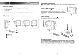
3.0 SYSTEM DESCRIPTION
3.1 Transient Voltage Surge Suppression (TVSS) and EMI/RFI Filters
These UPS components provide surge protection and filter both electromagnetic interference (EMI)
and radio frequency interference (RFI). They minimize any surges or interference present in the util-
ity line and keep the sensitive equipment protected.
3.2 Rectifier/Power Factor Correction (PFC) Circuit
In normal operation, the rectifier/power factor correction (PFC) circuit converts utility AC power to
regulated DC power for use by the inverter while ensuring that the waveshape of the input current
used by the UPS is near ideal. Extracting this sinewave input current achieves two objectives:
• The utility power is used as efficiently as possible by the UPS.
• The amount of distortion reflected on the utility is reduced.
This results in cleaner power being available to other devices in the building not being protected by
the UPStation GXT2-6000RT208.
3.3 Inverter
In normal operation, the inverter utilizes the DC output of the power factor correction circuit and
inverts it into precise, regulated sinewave AC power. Upon a utility power failure, the inverter
receives energy from the battery through the DC to DC converter. In both modes of operation, the
UPS inverter is on-line and continuously generating clean, precise, regulated AC output power.
3.4 Battery Charger
The battery charger utilizes energy from the utility power and precisely regulates it to continuously
float charge the batteries. The batteries are being charged whenever the UPStation GXT2-6000RT208
is plugged in, even when the UPS is not turned on.
Input Output
Inverter
Battery
Battery
Charger
DC to DC
Converter
Rectifier
/PFC
TVSS &
EMI/RFI
Filters
L1
G G
Dynamic
Bypass
L2
N
L1
L2
N

System Description
6
3.5 DC to DC Converter
The DC to DC converter utilizes energy from the battery system and raises the DC voltage to the opti-
mum operating voltage for the inverter. This allows the inverter to operate continuously at its opti-
mum efficiency and voltage, thus increasing reliability.
3.6 Battery
The UPStation GXT2-6000RT208 utilizes valve-regulated, nonspillable, flame retardant, lead acid
batteries. To maintain battery design life, operate the UPS in an ambient temperature of 68°F to 77°F
(20°C to 25°C). Optional external battery cabinets are available to extend battery run times.
3.7 Dynamic Bypass
The UPStation GXT2-6000RT208 provides an alternate path for utility power to the connected load in
the unlikely event of a UPS malfunction. Should the UPS have an overload, overtemperature or UPS
failure condition, the UPS automatically transfers the connected load to bypass. Bypass operation is
indicated by an audible alarm and illuminated amber Bypass indicator (other indicators may be illu-
minated to indicate the diagnosed problem).
The user may manually transfer the connected load from the inverter to bypass by pressing the
Standby button once.
NOTE
The bypass power path does NOT protect the connected equipment from disturbances
on the utility supply.

Major Components
7
4.0 MAJOR COMPONENTS
The GXT2-6000RT208 is composed of three major assemblies to provide easier handling, installation
and versatility.
4.1 Main Frame and Electronics
This 4U cabinet arrives without internal batteries to lighten the UPS for easier installation. Once the
cabinet has been placed in its final floor or rack position, the internal batteries may be installed. The
UPS is shipped with a basic hardwire distribution box.
Figure 1 6 kVA Dual Inverter GXT 2U (front and rear views)
4.2 Internal Battery Pack
The front bezels may be pulled forward and removed to
reveal the battery access door. The internal battery pack
is a compact assembly ready to slide into the battery
compartment after the front battery access door has been
opened. Electrical connection is automatic upon
insertion.
!
UPStation GXT
+
+
--
Input Circuit
Breaker
Support Base
Hardwire
Knockouts
External Battery
Connector
Cooling Fan
(1 of 4)
Intellislot
®
Port
REAR VIEWFRONT VIEW
Status Indicators
and Controls
DB-9
Communications
Port
REPO
Switch
Grounding
Electrode
Conductor
Output
Circuit
Breaker
Front Bezels (2)
Power Distribution Box
Standard Module
(See Section 4.3)
Battery Compartment (behind bezel);
Internal Battery Pack is shipped loose
(see Section 4.2)
WARNING:
!
!
!
+
-
12Vx12(144V)
9Ahi45W
WARNING:
ADVERTENCIA
:
AVERTISSEMENT
:

Major Components
8
4.3 Removable Power Distribution Box
The UPS is shipped with a basic hardwire power distribution pack installed. For maximum flexibility,
this may be easily replaced with either of two optional power distribution boxes that provide the ben-
efits of hardwire input and output plus manual bypass switch or plug/receptacle convenience with
manual bypass switch.
DISCONNECT BYPASS POWER TO
THE MANUAL BYPASS SWITCH.
PD-HDWR
Power Distribution Box With
Hardwire Connections
(Standard - Ships With UPS)
PD-HDWR-MBS
Power Distribution Box
With Hardwire Connections
and Manual Bypass Switch
(Optional)
PD-001
Power Distribution Box
With Wired Connections
and Manual Bypass Switch
(Optional)

What’s Included
9
5.0 WHAT’S INCLUDED
The GXT2-6000RT208 is shipped with the following items:
• GXT2-6000RT208 user manual
• Vertical display overlay
• Front bezels - 2
• Top bezels - 2
• Battery cover grille
• MultiLink software CD
• MultiLink serial cable, 10 ft (3m)
• Rack mount handles
• Support base - 2
• GEC ring connector
• Mounting hardware
• Configuration program disk
• Ferrite beads (2)
!
UPStation GXT
L1
L2
AC INPUT
- +
BATTERY
UPS ON
BYPASS
!
MultiLink
software CD
Mounting hardware
Front bezels
Vertical
display
overlay
Rack mount
handles
MultiLink
serial cable
10 ft (3m)
Top bezels
(tower use)
Configuration
disk
www.liebert.com
GXT 2U™ Configuration
Program
For use with LiebertGXT2U model UPS
systems
Ver sion 1.6
For Windows 95/98/NT
To Install:
Choose the Start button on the Taskbar
and select Run
Battery cover grille
Support base
with spacers
GEC connector
Ferrite
beads (2)

Installation and Configuration
10
6.0 INSTALLATION AND CONFIGURATION
This section includes instructions on how to install, configure and perform initial electrical checks of
your UPS installation.
DO NOT attempt to start the UPS, turn on any circuit breaker or energize the input power until
instructed to do so in 7.0 - Initial Startup and Electrical Checks.
Visually inspect the UPS for freight damage. Report damage to the carrier and your local dealer or
Liebert representative.
Install the UPS indoors in a controlled environment, where it cannot be accidentally turned off. Place
it in an area of unrestricted airflow around the unit, away from water, flammable liquids, gases, cor-
rosives and other conductive contaminants. Maintain a minimum clearance of 4" (100mm) in the front
and rear of the UPS. Maintain an ambient temperature range of 32°F to 104°F (0°C to 40°C).
6.1 Install the Main Cabinet
The GXT2-6000RT208 may be installed either as a tower unit or in a rack, depending on available
space and use considerations. Determine the type of installation and follow the appropriate instruc-
tions in either 6.1.1 - Tower UPS Installation or 6.1.2 - Installing the Adjustable Rack-Mount
Kit—Sold Separately.
6.1.1 Tower UPS Installation
When using the GXT2-6000RT208 in a tower configuration, use the included support base (shown
below, left) to stabilize the UPS.
If any external battery cabinets are added, they will include spacers to accommodate the additional
cabinets (shown below, right).
Figure 2 Support base and spacers
Attach Bezels to Top
When used as a tower, the GXT2-6000RT208 requires bezels attached to the top. To connect the
bezels:
1. Position the UPS so that the battery compartment is on the bottom.
2. Attach the top bezels by placing them on the mounting holes and sliding them toward the rear of
the UPS.
!
CAUTION
The UPS is heavy (see 14.0 - Specifications). Take proper precautions when lifting or
moving it.
NOTE
UPS operation in sustained temperatures above 77°F (25°C) reduces battery life.
4U Support Base
Spacers added to support
base to accommodate
additional battery cabinets
End Bases
2U Spacer

Installation and Configuration
11
6.1.2 Installing the Adjustable Rack-Mount Kit—Sold Separately
This kit contains parts needed to mount several different models of UPS and external battery cabi-
nets into EIA310-D standard four-post racks that are 18-32" deep (457-813mm). The weight limit per
pair of adjustable rack-mounting brackets is 200 pounds (91 kg).
Parts included are:
Tools needed for installation are:
• one Phillips screwdriver
• one 7mm wrench
The adjustable rack-mounting brackets feature retaining latches to prevent users from inadvertently
sliding the UPS or battery cabinet out of the rack.
To install the rack mount brackets:
1. Unpack two (2) rack-mounting bracket assemblies and
mounting hardware from this kit. Bracket assemblies are
interchangeable between left-hand or right-hand.
Remove inner member of each bracket assembly as shown
in at right by extending it to its outermost position,
depressing the retaining latch and then pulling the inner
member out of the bracket assembly.
2. Determine the height position inside the rack enclosure
where you want to mount the UPS or battery cabinet.
3. Install the rear member of each bracket assembly into rack
enclosure with two (2) M5 screws provided in this kit (see
figure at right). The return flanges on the bracket assembly
fit to the inside of rack mounting rails. Insert screws loosely
(finger-tight) into the top and bottom holes of the return
flange on the rear member. Extend the bracket assembly by
sliding the front member forward until it touches the front
rack mounting rail. Insert two (2) M5 screws loosely (finger-
tight) into top and bottom holes of the return flange on each
front member. Make sure bracket assemblies are at the
same mounting height on all four (4) rack mounting rails.
Item Quantity
Rear bracket members 2
Front bracket members 2
Inner bracket members 2
M4 x 8mm machine screws 16
M4 locking hex nuts 8
M5 x 16 mm machine screws 12
Grease packet. 1
!
CAUTION
Reduce the risk of tipping the rack enclosure by
placing the UPS or battery cabinet in the lowest
possible rack position.
Return
flanges
Inner
members
Front
members
Retaining
Latches
M5 screws
M5 screws
Front rack
mounting rails
Rear rack
mounting
rails

Installation and Configuration
12
4. Get eight (8) M4 screws and eight (8) M4 nuts from the
hardware pack in this kit. Each nut has a locking, nylon
insert that begins gripping the screw when it is halfway
tight. Make sure to tighten the nut and screw completely to
ensure locking action.Fasten the rear member and the front
member together using (4) screws and (4) nuts per bracket
assembly as shown in at right. For maximum support, insert
fasteners for each bracket assembly as far apart as possible,
depending on rack depth, while still joining both members
(see figures at right). Check alignment of bracket assemblies
and TIGHTEN ALL SCREWS FROM Steps 2 and 3.
5. Prepare the UPS or battery cabinet (the “equipment”) for
rack mounting by following instructions in the equipment’s
user manual. The equipment may require additional parts to
be added or parts to be removed for rack mounting. After it is
prepared, lay the equipment in rack-mounting position.
Fasten the inner members from Step 1 to the equipment on
both sides as shown at right with eight (8) M4 screws
provided in the kit. Make sure retaining latch is near the rear
of the equipment as shown (see figure at right).
6. Open the grease packet provided in the kit. Apply a 1" long
bead of grease at four (4) places inside the bottom, curved
tracks of the front members as shown below right. The grease
will allow the equipment to slide into the bracket assemblies
more easily.
7. Insert the equipment, with inner members attached in
Step 5, into the bracket assemblies by inserting the top and
bottom edges of the inner members into the top and bottom
curved tracks of the front members and sliding the
equipment into the rack (see figure at right). Ends of inner
members are tapered to allow the rear of the equipment to be
angled upward before insertion, if space allows.
Then the rear, bottom edges of the inner members can be
placed into the front edge of the bottom tracks and the front
of the equipment can be tipped up so they are level to insert
the top edges of the inner members before sliding the equip-
ment into the rack (see figure below right). The equipment
should move smoothly into the bracket assemblies. If it does
not, recheck the alignment of the front and rear members
from Steps 2 and 3.
8. Secure the front of the equipment to the rack mounting rails
to prevent the equipment from sliding out of position. If
securing holes are provided on the front of the equipment
that align with the center holes on the return flange of the
front members, you can use the four (4) extra M5 screws
provided in the kit to secure the equipment. Otherwise, the
equipment should be secured to the front of the rack with
four (4) customer-supplied fasteners.
!
6.
CAUTION
Lifting equipment into the rack may be a two-person
job, depending on the weight of the equipment. See
equipment’s user manual.)
32" rack
depth
M4 nuts
M4 nuts
M4
screws
18" rack
depth
M4 nuts
M4 nuts
M4
screws
UPS or battery
cabinet
Front
M4 screws
M4 screws
Retaining latch
UPS or
battery
cabinet
Apply
grease
(inside)
Apply
grease
Insert the UPS into the front
members, lift the front ...
... and push it
into the rack.

Installation and Configuration
13
6.2 External Battery Cabinet Installation
Optional Liebert external battery cabinets may be connected to the UPS to provide additional battery
run time. External battery cabinets are designed to be placed on one side of the UPS or stacked
beneath the UPS.
When the external battery cabinet is received, it should be inspected for freight damage. Report dam-
age to the carrier and your local dealer or Liebert representative.
To install an external battery cabinet:
1. For slide rail installations, first remove the top/side fin by sliding it forward and lifting it up.
Optional rack-mount handles are shipped with the external battery cabinet and may be installed
now. (Securing hardware and slide rails are sold separately. Please contact your local dealer or
Liebert representative for these additional options and any assistance needed.)
2. Fasten the slides into position with the screws according to the instructions included with the
slide rails.
3. Use the enclosed support bases for the tower option to
prevent the assembly from tipping over. One additional set
of support base extensions ships with each external battery
cabinet.
4. Connect the supplied external battery cabinet cable to either
of the connectors on the rear of the external battery cabinet,
then to the rear of the UPS.
5. The UPS is now equipped with additional backup battery
run time. For approximate battery run times, refer to Table
7 - Battery run times in this manual.
6. Do NOT turn on the battery cabinet circuit breaker at this
time. Please complete the remainder of the installation first.
!
CAUTION
The external battery cabinet(s) are heavy (see 14.0 - Specifications). External battery
cabinets can be used in rack-mount or tower configuration. Take proper precautions when
lifting them.
!
CAUTION
Verify that the battery cabinet circuit breaker is in the OFF position. Do no energize the
battery cabinet at this time. When installation is complete, you will be instructed to turn on
the circuit breaker.
NOTE
After installation is complete, you must use the included
configuration program to program the UPS for the
number of external battery cabinets connected.
Instructions for using the configuration program follow
in 8.0 - Configuration Program.
+
+
--
Support Base With
Spacers for External
Battery Cabinets
UPS and Four External Battery
Cabinets With Support Base

Installation and Configuration
14
6.3 Connect Input/Output Power
The UPS ships with the basic hardwire box attached. If an
optional model is to be used, remove the standard box and
install the optional box using the three captive mounting
screws marked in the illustration, below, right.
6.3.1 Replacing a power distribution box
Whenever a power distribution box is not attached to a UPS,
the cover must be slid over the electrical connectors to prevent
damage or injury.
1. On the power distribution box attached to the UPS,
locate the three captive mounting screws holding the box
to the UPS (see illustration above, right).
2. Turn the screws until the box can be pulled away from the
UPS. Exercise care to avoid removing screws from the
hardwire box.
3. On the replacement power distribution box to be
attached to the UPS, loosen the cover over the electrical
connectors by backing out the three screws one turn each.
4. Slide the cover open to expose the electrical connectors.
5. Gently retighten the three screws loosened in Step 3.
6. Align the connectors on the box and UPS.
7. Push the box into place.
8. Holding the box firmly against the UPS, tighten the three
captive mounting screws until the box is secure. Do not
overtighten.
6.3.2 Distribution Box Electrical Connections
Electrical connections are made through a removable power distribution box that attaches to the rear
of the UPS.
The installer must provide a 30A branch circuit breaker. The input circuit breaker on the distribution
box and the output circuit breaker on the rear fixed-panel of the UPS disconnect all power between
the main cabinet and the distribution box.
Models equipped with a manual bypass switch pass utility power directly to the bypass switch from
the input terminal block. The input circuit breaker on the distribution box does not disconnect power
from the manual bypass switch.
Figure 3 30A branch circuit breaker connection diagram
DISCONNECT BYPASS POWER TO
THE MANUAL BYPASS SWITCH.
Mounting screws
for removable box
Slide
cover
over
connec-
tors
Loosen screws
to move cover
PD-HDWR Distribution Box PD-HDWR-MBS Distribution Box
Utility Utility
Input
Input
Output
Output
30A External
Branch Circuit
Breaker
30A External
Branch Circuit
Breaker
30A Input
Circuit
Breaker
30A UPS Output
Circuit Breaker
30A UPS Output
Circuit Breaker
30A Input
Circuit
Breaker
Byp
Inv
UPS - PFC, Battery, Inverter UPS - PFC, Battery, Inverter
/