Page is loading ...

UPStation GXT 2U
700 - 3000 VA 230V
User Manual
English


1
WARNING:
Opening or removing the cover may expose you to
lethal voltages within this unit even when it is apparently not operating
and the input wiring is disconnected from the electrical source.
Observe all cautions and warnings in this manual. Failure to do so
MAY result in serious injury or death. Refer all UPS and battery ser-
vice to qualified service personnel. Do not attempt to service this prod-
uct yourself. Never work alone.
SAVE THESE INSTRUCTIONS.
This Manual Contains Important Safety Instructions.
Read all safety, installation, and operating instructions before operating
the Uninterruptible Power System (UPS). Adhere to all warnings on the
unit and in this manual. Follow all operating and user instructions. Individ-
uals without previous training can install and operate this equipment.
It is not intended for use with life support and other designated "critical"
devices. Maximum load must not exceed that shown on the UPS rating
label. The UPS is designed for data processing equipment. If uncertain,
consult your local dealer or Liebert Representative. See the Limited War-
ranty.
This UPS is designed for use on a properly grounded (earthed), 200 - 240
VAC, 50Hz or 60Hz supply. Installation instructions and warning notices
are located in this manual.
ELECTROMAGNETIC COMPATIBILITY - The GXT 2U Series complies
with the requirements of the EMC directive 89/336/EEC and the published
technical standards. Continued compliance requires installation in accor-
dance with these instructions and use of manufacturer approved acces-
sories only.
Operate the UPS in an indoor environment only in an ambient tempera-
ture range of 0°C to +40°C (32°F to +104°F). Install it in a clean environ-
ment, free from conductive contaminates, moisture, flammable liquids,
gasses, or corrosive substances.
WARNING:
This
UPS should not be supplied from electrical power
systems of the “IT” (Impedance á Terre) type. (IEC 364 - ELECTRICAL
INSTALLATION OF BUILDINGS).
IMPORTANT SAFETY INSTRUCTIONS

2
This UPS contains no user serviceable parts except the internal battery
packs. The UPS ON/OFF pushbuttons do not electrically isolate internal
parts. Under no circumstances attempt to gain access internally other
than to replace the batteries due to risk of electric shock or burn. Do not
continue to use the UPS if the front panel indications are not in accor-
dance with these operating instructions, or the UPS performance alters in
use. Refer all faults to your local dealer, Liebert Representative or the Lie-
bert Worldwide Support Group.
Servicing of batteries should be performed or supervised by personnel
knowledgeable of batteries and the required precautions. Keep unautho-
rized personnel away from the batteries. PROPER DISPOSAL OF BAT-
TERIES IS REQUIRED. REFER TO YOUR LOCAL LAWS AND
REGULATIONS FOR BATTERY DISPOSAL REQUIREMENTS. Never
block or insert any object into the ventilation holes or other openings of
the UPS.
DO NOT CONNECT equipment that could overload the UPS or demand
DC current from the UPS, for example: electric drills, vacuum cleaners,
laser printers, hairdryers or any appliance using half wave rectification.
Storing magnetic media on top of the UPS may result in data loss or cor-
ruption.
Turn the UPS OFF and isolate the UPS before cleaning. Use only a soft
cloth, never liquid or aerosol cleaners. Keep the front and rear vents free
of dust accumulation that could restrict airflow.
When replacing batteries, replace with the same Liebert authorized
replacement battery kits.
CAUTION:
Do not dispose of battery or batteries in a fire. The battery
may explode.
CAUTION:
Do not open or mutilate the battery or batteries.
Released electrolyte is harmful to skin and eyes. It may be toxic.
CAUTION:
A battery can present a risk of electrical shock and high
short circuit current. The following precautions should be observed when
working on batteries:
-Remove watches, rings, or other metal objects.
-Use tools with insulated handles.

3
Congratulations on your choice of the Liebert UPStation GXT 2U Uninter-
ruptible Power System (UPS). It provides conditioned power to micro-
computers and other sensitive electronic equipment.
Upon generation, AC power is clean and stable. However, during trans-
mission and distribution it may be subject to voltage sags, spikes, or com-
plete power failure that may interrupt computer operations, cause data
loss, or even damage equipment. The UPStation GXT 2U protects equip-
ment from these disturbances.
The UPStation GXT 2U comes in nominal power ratings of 700, 1000,
1500, 2000, & 3000 VA. Complete model specifications appear at the end
of this manual.
The UPStation GXT 2U is a compact, "on-line" UPS. An "on-line" UPS
continuously conditions and regulates its output voltage, whether the util-
ity power is present or not. It supplies connected equipment with clean
sinewave power. Sensitive electronic equipment operates best from sine-
wave power.
For ease of use, the UPStation GXT 2U contains a light emitting diode
(LED) display to indicate either "load percentage" or "battery capacity"
depending upon the mode of operation. It also provides self-diagnostic
tests, a combination ON/Alarm Silence/Manual Battery Test button, a
combination OFF/Bypass button, user configurable program, and two lev-
els of alarms when the unit is operating on battery.
The UPStation GXT 2U has an interface port for communications
between the UPS and a Network server or other computer systems. This
port provides detailed operating information including voltages, currents,
and alarm status to the host system when used in conjunction with Liebert
MultiLink™ software. MultiLink software can also remotely control UPS
operation.
INTRODUCTION

4

5
TRANSIENT VOLTAGE SURGE SUPPRESSION (TVSS) AND EMI/RFI
FILTERS
These UPS components provide surge protection, and filter both electro-
magnetic interference (EMI) and radio frequency interference (RFI). They
minimize any surges or interference present in the mains line and keep
the sensitive equipment protected.
RECTIFIER/POWER FACTOR CORRECTION (PFC) CIRCUIT
In normal operation, the rectifier/power factor correction (PFC) circuit con-
verts utility AC power to regulated DC power for use by the inverter, while
ensuring that the waveshape of the input current used by the UPS is near
ideal. Extracting this sinewave input current achieves two objectives: the
utility power is used as efficiently as possible by the UPS, and the amount
of distortion reflected on the mains is reduced. This results in cleaner
power being available to other devices in the building not being protected
by the UPStation GXT 2U.
INVERTER
In normal operation, the inverter utilizes the DC output of the power factor
correction circuit and "inverts" it into precise, regulated sinewave AC
power. Upon a utility power failure, the inverter receives its required
energy from the battery through the DC to DC converter. In both modes
of the operation, the UPS inverter is on-line and continuously generating
clean, precise, regulated AC output power.
MAJOR COMPONENTS
TVSS and
EMI/RFI
Filters
INVERTER
BATTERY
CHARGER
DYNAMIC
BYPASS
RECTIFIER
/ PFC
INPUT
OUTPUT
BATTERY
DC TO DC
CONVERTER
N
G
N
G
LL

6
BATTERY CHARGER
The battery charger utilizes energy from the mains and precisely regu-
lates it to continuously "float" charge the battery system. The battery sys-
tem charges whenever the UPStation GXT 2U is plugged in.
DC TO DC CONVERTER
The DC to DC converter utilizes energy from the battery system and
raises the DC voltage to the optimum operating voltage for the inverter.
This allows the inverter to operate continuously at its optimum efficiency
and voltage, thus increasing reliability.
BATTERY
The UPStation GXT 2U utilizes valve regulated, nonspillable, flame retar-
dant lead acid batteries. At typical room temperatures and with the UPS
float charging, the battery system will last many years. Optional external
battery cabinets are available to provide extended battery run times.
DYNAMIC BYPASS
The UPStation GXT 2U provides an alternate path for mains to the con-
nected load, in the unlikely event of a UPS malfunction. Should the UPS
have an overload, over temperature, or UPS failure condition, the UPS
automatically transfers the connected load to bypass. Bypass operation
is indicated by an alarm and illuminated Amber Bypass LED (other LED's
may be illuminated to indicate the diagnosed problem). To manually
transfer the connected load from the inverter to bypass, press the "OFF"
button once.
NOTE: The bypass power path does NOT protect the connected equip-
ment from disturbances or an outage on the mains supply.

7
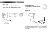
GXT 2U (Rear View)
TM
AC Input
Support Base
Output
Sockets
External Battery
Connector
Cooling Fan
Intellislot Port
DB-9
Communications
Port

8

9
Tower UPS Installation
When using the GXT 2U in a tower configuration,
use the included support base (as shown) to sta-
bilize the UPS.
If any additional cabinets are added, they will
include spacers to accomodate the additional
cabinets.
Rack UPS Installation
Rack-Mount UPS Conversion and Installation
1.
CAUTION:
The UPS is heavy (see specifications). Take proper
precautions when lifting or moving it.
2. Visually inspect the UPS for freight damage. Report damage to the
carrier and your local dealer or Liebert Representative.
3. NOTE: When rack mounted, the UPS MUST be supported by a
shelf, fixed rails or slide rails on each side. The Rack Mount Handles
WILL NOT support the weight of the UPS.
4. For slide rail installations, first remove the top/side fin. Top/side fin
slides forward and then lift up to remove. Optional rack-mount han-
dles are shipped with the UPS and maybe installed at this time if
desired.
5. Securing hardware and slide rails are sold separately. Please con-
tact your local dealer or Liebert Representative for these additional
options and any assistance needed. Fasten the slides into position
with the screws per the instructions included with the slide rail kits.
6. Locate UPS indoors in a controlled environment, where it cannot be
accidentally turned off. Locate it in an area of unrestricted airflow
around the unit, away from water, flammable liquids, gases, corro-
sives, or conductive contaminants. Maintain a minimum of 100 mm
INSTALLATION

10
(4 inches) clearance in front and rear of the UPS. Maintain an ambi-
ent temperature range of 0° to 40° C (32° to 104° F0° to 40° C).
NOTE: UPS operation in temperatures above 25° C (77° F) reduces
battery life.
7. Remove the front plastic bezel by grabbing and pulling forward evenly
on both sides. There are 2 front panel overlays, the tower configura-
tion ships on the unit. For Rack mounting, remove the front plastic
bezel cover and then the Tower display template overlay. Snap the
front plastic bezel cover back into place.
8. The UPS is now ready to be placed into the equipment rack.
9. Once the UPS is installed in the rack, the load may be connected.
Ensure the load equipment is turned off; plug all loads into the output
receptacles on the rear of the UPS.
10. Plug the UPS into a dedicated wall socket properly protected in
accordance with Local Codes and Regulations. The wall socket must
be grounded (earthed).
11. Turn ON the UPS by pressing the ON button; then turn ON the con-
nected load equipment. The UPS is now providing conditioned power
to your equipment.

11
Optional Rack Slide Installation
1. Remove the decora-
tive Top / Side Cover
by sliding it forward to
disengage inner tabs
and lifting it upward.
To change orientation
of the Display, remove
the Front Plastic Bezel
Cover by pulling it for-
ward. Remove the
tower Display Tem-
plate by lifting it to
reveal the rack-mount
Display Template.
Replace the Front
Plastic Bezel Cover.
2. Locate (2) Rack Mount
Handles and (8) M4 Truss Head Screws in the accessories box
packed with the UPS. Fasten the Rack Mount handles to the sides of
the UPS using (4) Screws for each Flange.
NOTE: For rack-mount installation, the UPS must be supported by a
shelf or slide rails. The Securing Flanges WILL NOT support the
weight of the UPS.
CAUTION:
REDUCE THE RISK OF TIPPING THE RACK
ENCLOSURE BY PLACING THE UPS IN THE LOWEST POSSIBLE
RACK POSITION.
+
–
UPStation GXT
AC INPUT BATTERY UPS ON BYPASS
+
–
UPStation GXT
AC INPUT BATTERY UPS ON BYPASS
+
–
AC INPUT
BATTERY
UPS ON
BYPASS
UPStation GXT

12
3. Unpack the (2) Slide Assem-
blies and mounting hardware
from this kit. The Slide
Assemblies are interchange-
able between left-hand or
right-hand. Remove the Inner
Member of each Slide Assem-
bly (as seen on right) by
extending it to its outermost
position, depressing the Lock-
ing Mechanism and then pull-
ing the Inner Member from the
Slide Assembly.
4. Fasten the Inner Members
from Step 3 to the UPS on
both sides as shown below
with (8) M4 Truss Head
Screws provided in the acces-
sories box of the UPS.
5. Locate in this kit (2) Mounting Brackets for the Slide Assemblies. The
Brackets allow up to 203 mm (8 inches) adjustment of the Slide
Assembly mounting position front-to-back on the Rack Mounting
Rails. Determine which adjustment holes to use on the Bracket, and
attach it to the Slide Assembly on the stationary Outer Member using
the Bar Nuts and Screws provided in this kit. Insert (2) Screws from
the inside of each Slide Assembly as shown.
NOTE: Bar nuts may not be required on all installations depending on
the type of racks being used.
A
C
I
N
P
U
T
B
A
T
T
E
R
Y
U
P
S
ON
B
Y
P
A
S
S

13
6. Install the Slide Assemblies, with attached Mounting Brackets from
Step 5, into the Rack Enclosure and Screws provided in this kit. The
return flanges on the Mounting Brackets and Outer Members fit to the
inside of the Rack Mounting Rails. Insert the (8) Screws loosely (fin-
ger-tight). Make sure the Slide Assemblies are in the same alignment
position on all (4) Rack Mounting Rails. After alignment is checked,
TIGHTEN ALL SCREWS. Then insert the UPS, with Inner Members
attached from Step 4, into the Slide Assemblies. You may need to
depress the Locking Mechanisms on the Inner Members and Outer
Members of the Slide Assemblies to allow the Slides to retract. The
UPS should now move smoothly forward and backward on the Slide
Assemblies. If not, recheck alignment. Secure the UPS Rack Mount
Handles from Step 3 to the Rack Mounting Rails with (4) customer-
supplied fasteners.
UPStation GXT

14
External Battery Cabinet Installation
Optional Liebert external battery cabinets may be connected to the UPS
to provide additional battery run time. External battery cabinets are
designed to be placed all on one side of the UPS or stacked beneath the
UPS. There is no limit to the number of external battery cabinets that can
be used but each cabinet will increase the battery recharge time.
1.
CAUTION:
The external battery cabinet(s) are heavy (see spec-
ifications). External battery cabinets can be used in rack-mount or
tower configuration. Take proper precautions when lifting them.
2. Visually inspect the external battery cabinet for freight damage.
Report damage to the carrier and your local dealer or Liebert Repre-
sentative.
3. For slide rail installations, first remove the top/side fin. Top/side fin
slides forward and then lift up to remove. Optional rack-mount han-
dles are shipped with the external battery cabinet and maybe
installed at this time if desired.
4. Securing hardware and slide rails are sold separately. Please con-
tact your local dealer or Liebert Representative for these additional
options and any assistance needed.
Fasten the slides into position with the
screws per the instructions included
with the slide rails.
5. Use the enclosed support bases for the
tower option to prevent tip-over. One
additional set of support base exten-
sions ship with each external battery kit
to accommodate the external battery
cabinets.
6. Connect the supplied external battery
cabinet cable to the rear of the exter-
nal battery cabinet, then to the rear of
the UPS.
7. Turn the battery breaker on the rear of
the external battery cabinet "ON".
8. The UPS is now equipped with additional backup battery runtime. For
approximate battery runtimes please refer to the Battery Run Time
Charts in the back of this manual.
NOTE: You can use the Configuration Program to select the number
of external battery cabinets connected to the UPS.

15
ON/Alarm Silence/Manual Battery Test Button
This button controls output power to connected load(s) and has
three functions: ON, Alarm Silence, and Manual Battery Test.
Pressing this button will start up the UPS in order to provide con-
ditioned and protected power.
To silence alarms, press this button for at least one half second while
alarm conditions are present. After the alarm is silenced, the UPStation
GXT 2U will reactivate the alarm system to alert of additional problems.
NOTE: The LOW BATTERY and BYPASS reminder alarms CANNOT be
silenced.
To initiate a manual battery test, press the ON button for at least one sec-
ond while operating from mains power and no alarm conditions are
present.
If the bottom two LEDs do not illuminate during a Battery Test, allow the
UPS to recharge the batteries for 24 hours. After 24 hours, retest the bat-
teries. If the batteries have been retested and the bottom two LEDs still
do not illuminate, contact your local dealer, Liebert Representative or the
Liebert Worldwide Support Group.
CONTROLS AND INDICATORS
+
UPStation GXT
AC INPUT
BATTERY
UPS ON
BYPASS
+
UPStation GXT
AC INPUT BATTERY UPS ON BYPASS

16
OFF/ Manual Bypass Button
This button controls output power to connected load(s) and has
dual functions: OFF and Manual Bypass.
CAUTION:
Pressing this button once will cause the load to be trans-
ferred to bypass power. Pressing this button a second time within 4 sec-
onds will result in loss of power to the output receptacles and connected
loads. Perform all necessary shutdown procedures on connected loads
before pressing this button twice.
Load/Battery Level Indicators (4 Green, 1 Amber)
The Load/Battery Level indicators have dual functions. During normal
mode operation LED indicators display the approximate electrical load
placed upon the UPS; and during battery mode operation LED indicators
display approximate battery capacity.
The UPStation GXT 2U is equipped with automatic and remote battery
test features. The automatic test occurs every 14 days (this option is user
configurable) if utility has not been interrupted. Should the battery fail this
test, the red fault indicator LED along with the A and C diagnostic LEDs
will illuminate and an alarm will sound (refer to Troubleshooting Guide).
The remote test feature functions with either MultiLink® 2 or MultiLink®
SNMP Manager software and can remotely initiate the battery test.
Fault Indicator LED (Red)
The Fault indicator LED is illuminated if the UPS has detected a problem.
Also, one or more of the load/battery level indicators may be illuminated
(Refer to Troubleshooting Guide).
Bypass Indicator LED (Amber)
The Bypass indicator LED is illuminated when the UPS is operating from
bypass power. An alarm will sound indicating the UPS detected a prob-
lem, or the manual bypass function has been activated.
UPS ON Indicator LED (Green)
The UPS ON indicator LED is illuminated when the UPS inverter is oper-
ating and supplying power to your connected loads.
Battery Indicator LED (Amber)
The Battery indicator LED is illuminated when the UPS is operating on
battery.

17
AC Input Indicator LED (Green)
The AC Input indicator LED is illuminated when mains power is available
and within the input specifications.
Output Voltage Selection
The Output Voltage is user configurable, and is designed to allow select-
ing or changing the desired output voltage to match the mains via the
GXT2 Configuration Program provided with the UPS. The settings to
choose from are 200, 208, 220, 230, and 240 VAC output. The factory
default setting is 230 VAC.
NOTE: Never change the voltage settings while UPS is on and powering
connected loads.
NOTE: Setting output voltage to 200 VAC will cause UPS unit to be der-
ated (700/1000 VA to 90%, 1500/2000/3000 VA to 80%) of the VA and
Watt ratings listed in specification section.

18
/