Page is loading ...

IDS-710HP Hardware Installation Guide
PoE Managed Industrial Ethernet Switches
Updated: April 2020
Version: A.07.04.2020
Document Part# 5500455-10
www.perle.com

IDS-710HP Hardware Installation Guide
THE SPECIFICATIONS AND INFORMATION REGARDING THE PRODUCTS IN THIS GUIDE ARE SUBJECT TO CHANGE
WITHOUT NOTICE. ALL STATEMENTS, INFORMATION, AND RECOMMENDATIONS IN THIS GUIDE ARE BELIEVED TO BE
ACCURATE BUT ARE PRESENTED WITHOUT WARRANTY OF ANY KIND, EXPRESS OR IMPLIED. USERS MUST TAKE
FULL RESPONSIBILITY FOR THEIR APPLICATION OF ANY PRODUCTS.
This equipment has been tested and found to comply with the limits for a Class A digital device, pursuant to part 15 of the FCC
rules. These limits are designed to provide reasonable protection against harmful interference when the equipment is operated in a
commercial environment. This equipment generates, uses, and can radiate radio-frequency energy and, if not installed and used in
accordance with this hardware guide may cause harmful interference to radio communications. Operation of this equipment in a
residential area is likely to cause harmful interference, in which case users will be required to correct the interference at their own
expense.
Modifications to this product not authorized by Perle could void the FCC approval and negate your authority to operate the product.
Perle Systems Limited reserves the right to make changes without further notice, to any products to improve reliability, function, or
design.
Perle Systems Limited, the Perle logo, and IDS Switch are trademarks of Perle Systems Limited.
©2020. Perle Systems Limited.
Perle Systems Limited
60 Renfrew Drive,
Markham, Ontario, Canada
L3R 0E1

Table of Contents
Preface . . . . . . . . . . . . . . . . . . . . . . . . . . . . . . . . . . . . . . . . . . . . . . . . . . . . . . . . . . . . . . . . . . . . . . . . . . . . . . . . . . . . . . . . . . . . . . . . . . . . . . . .2
Overview . . . . . . . . . . . . . . . . . . . . . . . . . . . . . . . . . . . . . . . . . . . . . . . . . . . . . . . . . . . . . . . . . . . . . . . . . . . . . . . . . . . . . . . . . . . . . . . . . . . . . .3
Switch Models Views . . . . . . . . . . . . . . . . . . . . . . . . . . . . . . . . . . . . . . . . . . . . . . . . . . . . . . . . . . . . . . . . . . . . . . . . . . . . . . . . . . . . . . . 4
LED Indicators . . . . . . . . . . . . . . . . . . . . . . . . . . . . . . . . . . . . . . . . . . . . . . . . . . . . . . . . . . . . . . . . . . . . . . . . . . . . . . . . . . . . . . . . . . . . . 4
Port Status Indicators . . . . . . . . . . . . . . . . . . . . . . . . . . . . . . . . . . . . . . . . . . . . . . . . . . . . . . . . . . . . . . . . . . . . . . . . . . . . . . . . . . . . . . 6
Terminal Block Connectors . . . . . . . . . . . . . . . . . . . . . . . . . . . . . . . . . . . . . . . . . . . . . . . . . . . . . . . . . . . . . . . . . . . . . . . . . . . . . . . . . 8
Installation . . . . . . . . . . . . . . . . . . . . . . . . . . . . . . . . . . . . . . . . . . . . . . . . . . . . . . . . . . . . . . . . . . . . . . . . . . . . . . . . . . . . . . . . . . . . . . . . . . . . 9
Grounding the IDS Switch . . . . . . . . . . . . . . . . . . . . . . . . . . . . . . . . . . . . . . . . . . . . . . . . . . . . . . . . . . . . . . . . . . . . . . . . . . . . . . . . . .9
Connecting Power to the IDS Switch . . . . . . . . . . . . . . . . . . . . . . . . . . . . . . . . . . . . . . . . . . . . . . . . . . . . . . . . . . . . . . . . . . . . . . . 9
Wiring the Relay Alarm . . . . . . . . . . . . . . . . . . . . . . . . . . . . . . . . . . . . . . . . . . . . . . . . . . . . . . . . . . . . . . . . . . . . . . . . . . . . . . . . . . . .10
Wiring Digital Input . . . . . . . . . . . . . . . . . . . . . . . . . . . . . . . . . . . . . . . . . . . . . . . . . . . . . . . . . . . . . . . . . . . . . . . . . . . . . . . . . . . . . . .10
Connecting the Console Port . . . . . . . . . . . . . . . . . . . . . . . . . . . . . . . . . . . . . . . . . . . . . . . . . . . . . . . . . . . . . . . . . . . . . . . . . . . . . .11
Connecting Data Ports . . . . . . . . . . . . . . . . . . . . . . . . . . . . . . . . . . . . . . . . . . . . . . . . . . . . . . . . . . . . . . . . . . . . . . . . . . . . . . . . . . . .12
Resetting the Switch . . . . . . . . . . . . . . . . . . . . . . . . . . . . . . . . . . . . . . . . . . . . . . . . . . . . . . . . . . . . . . . . . . . . . . . . . . . . . . . . . . . . . .13
Configuring the IDS Switch . . . . . . . . . . . . . . . . . . . . . . . . . . . . . . . . . . . . . . . . . . . . . . . . . . . . . . . . . . . . . . . . . . . . . . . . . . . . . . . .16
Appendix A - Technical Specifications . . . . . . . . . . . . . . . . . . . . . . . . . . . . . . . . . . . . . . . . . . . . . . . . . . . . . . . . . . . . . . . . . . . . . . . . .17
Appendix B - Sample Labels . . . . . . . . . . . . . . . . . . . . . . . . . . . . . . . . . . . . . . . . . . . . . . . . . . . . . . . . . . . . . . . . . . . . . . . . . . . . . . . . . . .21
Appendix C - Mechanical Drawings . . . . . . . . . . . . . . . . . . . . . . . . . . . . . . . . . . . . . . . . . . . . . . . . . . . . . . . . . . . . . . . . . . . . . . . . . . .22
Appendix D - DIN Rail and Wall Mounting . . . . . . . . . . . . . . . . . . . . . . . . . . . . . . . . . . . . . . . . . . . . . . . . . . . . . . . . . . . . . . . . . . . . .23
Appendix E - IDS Maintenance . . . . . . . . . . . . . . . . . . . . . . . . . . . . . . . . . . . . . . . . . . . . . . . . . . . . . . . . . . . . . . . . . . . . . . . . . . . . . . . .25
Appendix F - Cables and Connectors . . . . . . . . . . . . . . . . . . . . . . . . . . . . . . . . . . . . . . . . . . . . . . . . . . . . . . . . . . . . . . . . . . . . . . . . . .26

2
IDS-710HP Hardware Installation Guide
Preface
Audience
This guide is for the network or computer technician responsible for installing Perle IDS-
710HP Switch. Familiarity with the concepts and terminology of Ethernet and local area
networks is required.
Purpose
This document describes the hardware and physical characteristics of the Perle IDS-
710HP Switch. It covers hardware features as well as installation and operation of the
switch. This document does not cover how to configure your Perle IDS-710HP Switch.
Information to configure your Perle IDS-710HP can be found in the IDS PoE Switches
User Guide.
Package Contents
• IDS-710HP Switch with attached DIN rail mounting bracket
• IDS-710HP Switches Quick Start Guide
Document Conventions
This document contains the following conventions:
Most text is presented in the typeface used in this paragraph. Other typefaces are used to
help you identify certain types of information. The other typefaces are:
Note: Means reader take note: notes contain helpful suggestions.
Caution: Means reader be careful. In this situation, you might perform an action that
could result in equipment damage or loss of data.
Warning: IMPORTANT SAFETY INSTRUCTIONS
Means danger. You are in a situation that could cause bodily injury. Before you work on
any equipment, be aware of the hazards involved with electrical circuitry and be familiar
with standard practices for preventing accidents. Only qualified personnel should connect
power to this unit.

3
IDS-710HP Hardware Installation Guide
Overview
This chapter discusses the following topics:
Switch Models Views
LED Indicators
Ports
Port Status Indicators
Terminal Block Connectors
Installation
The table below gives a brief overview of the models covered in this guide. For more
details and for the most up-to-date list of models, please refer to the product pages at:
www.perle.com
Standard Models
10/100/1000
Base-T
Ethernet Ports
PoE Enabled
Fixed SFP
Port
Software Set Temp
IDS-710HP 8 2 Pro Standard
IDS-710HP-XT 8 2 Pro Industrial

4
IDS-710HP Hardware Installation Guide
Switch Models Views
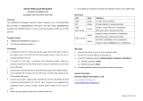
IDS-710HP (including XT models)
LED Indicators
PWR (Power Inputs)
1 – Reset / FS (Fast Setup) 6 – SFP slots
2 – Status LEDs 7 – 10/100/1000Base-T Ethernet Ports
with PoE/PoE+/PoE++ capability
3 – Terminal Block for Digital Input and
Relay
8 – Terminal Block for Power 1, 2
4 – SFP status LEDs 9 – Wall Mount Bracket Screw Holes
5 – Console Port – MicroUSB 10 – DIN Rail Clip
State Description
Green P1 and P2 power within specifications
Yellow - solid P1 or P2 providing power within specifications

5
IDS-710HP Hardware Installation Guide
Sys (System Status)
Alr (Alarm)
Ports
10/100/1000Base-T Ports with PoE/PoE+/PoE++ capability
These ports provide the standard 10/100/1000 Mb/s Ethernet through twisted pair (UTP)
cables of up to 100 meters (328ft) in length. Ports 1 through 8 can provide power to PoE/
PoE+/PoE++ PD devices.
SFP Slots
The SFP slots can accommodate industry standard SFPs from Perle or other suppliers.
These SFPs can be fiber or copper. The fiber SFP run at a speed of 1000 or 2500 Mbps.
The copper SFP are SGMII based and can support speeds of 10/100/1000 Mbps.
USB Console Port
The MicroUSB port is the switch’s console port. When connected the port presents a
serial interface that can be used from a PC Terminal emulation program (such as PuTTY).
This provides access to the switch management function using the industry standard CLI
command set.
Red Neither P1 and P2 providing power within specifications
State Description
State Description
Green - blinking (after power on) System booting
Green - solid System ready/operating normally
Green - blinking slowly Fast Setup Mode activated/port available
Green - blinking fast Fast Setup Mode activated/no port available
Red Hardware fault or firmware load error
State Description
Off No alarms configured
Green - solid Alarms configured, but no alarms detected
Red solid Alarm condition detected
Red blinking Alarm condition detected and Alarm Relay activated

6
IDS-710HP Hardware Installation Guide
Power Connector
The power input connector has provisions for dual inputs. Two independent power
sources can be used to power the switch. If one power input fails, the other power input
will power the switch.
See - Terminal Block Connectors
Alarm Relay Connector
The Alarm Relay can be energized by the software or hardware under certain conditions.
It can then be used to trigger an external alarm circuit such as a light or sounding device.
This connector provides a Normally opened (NO) dry contact on the connector block.
Digital Input Connector
A Digital Input is provided. It can be used for the generation of alarms (SNMP trap, ener-
gizing of on board Alarm Relay etc.).
Port Status Indicators
Ethernet Port Status Indicators
Port Link / Speed
State Description
LED 1: Green LED 2: Off 1000 Mbps
LED 1: Green LED 2: Green 100 Mbps
LED 1: Off LED 2: Green 10 Mbps
On solid Port Link
Random blinking Port Link and Activity
Slow blinking Error disabled
Rapid blinking Port in Fast Setup Mode

7
IDS-710HP Hardware Installation Guide
SFP Status LEDs
Each SFP has a corresponding LED to indicate the current state of the fiber link.
State Description
Green Fiber link established
Green flashing Link/activity
Off No Link

8
IDS-710HP Hardware Installation Guide
Terminal Block Connectors
P1(+/-) — Power Input 1.
P2 (+/-) — Power Input 2.
Either P1 or P2 can power the unit. When both are connected, one will act as a backup.
IN(+/-) — Digital Input. Dry Contact.
Relay — Normally Open (NO) relay.

9
IDS-710HP Hardware Installation Guide
Installation
This chapter discusses the following topics:
General Cautions and Warnings
Grounding the IDS Switch
Connecting Power to the IDS Switch
Wiring the Relay Alarm
Wiring Digital Input
Connecting the Console Port
Connecting Data Ports
Resetting the Switch
Configuring the IDS Switch
General Cautions and Warnings
Warning: Power sources must be off prior to beginning the power connection steps. Read the installa-
tion instructions before you connect the unit to its power source.
Warning: Ensure that the voltage and current ratings of the intended power source are appropriate for
the IDS switch as indicated on the product label.
Warning: Ensure that the installation and electrical wiring of the equipment is performed by trained
and qualified personnel and that the installation complies with all local and national electrical codes.
Warning: This unit should be installed in a restricted access location where access can only be gained
by service personnel or users who have been instructed about the reasons for the restrictions applied to
the location and about any precautions that shall be taken; and access is through the use of a tool or
lock and key, or any means of security, and is controlled by the authority responsible for the location.
Warning: The safety of any system incorporating the equipment is the responsibility of the assembler of
the system.
Warning: If the unit is installed vertically in a living or office environment, the device must be operated
exclusively in switch cabinets with fire protection characteristics in accordance with EN-62368-1
Warning: The working voltage inputs are designed for operation with Safety extra low Voltage (SELV).
Connect only to SELV circuits with voltage restrictions in line with IEC/EN 62368-1.
Grounding the IDS Switch
If your installation requires additional grounding, follow this procedure.
Grounding the chassis requires the following items:
• One grounding lug (not provided)
• One 12AWG wire (not provided)
Follow the manufacturers instructions for attaching the ground wire to the grounding lug.
The grounding lug can be found at the bottom of the IDS switch.
Attach the grounding lug to the chassis and secure with the grounding screw provided.
Connecting Power to the IDS Switch
The IDS switch has two power inputs that can be connected simultaneously to provide
redundant power. If one power source fails the other source acts as a backup, and powers
the switch
Wiring with suitable temperature ratings must be used. Refer to specification section for
details. Use copper wire only if the terminal is only for connection to copper wire.
1. Ensure the power source is off prior to connection.
2. Strip both (12-20AWG) wires 7-8 mm(5/16th).

10
IDS-710HP Hardware Installation Guide
3. Loosen the terminal block screws and connect positive (+) / negative (-) wires into the
+/- terminals.
4. Tighten terminal screws (0.5Nm torque). Ensure the wires are securely fastened.
5. Re-insert the Terminal Block connector if removed, Turn on power source. Check
LED indicators in the guide for power status
6. Connect P2 (power source 2, beginning at Step 1)
7. Ensure that there is one individual conductor for each clamping point.
See Terminal Block Connectors.
Wiring the Relay Alarm
The IDS switch has a relay with a Normally Open (NO) terminal pair. The relay connec-
tion are located just to the left of the power terminal. They are the bottom two terminal
connections. Using this, the IDS switch can be connected to an external powered device
such as a siren or light for visual or audible notification of an alarm status.
1. Ensure the power source is off prior to connection.
2. Strip 2x12-20AWG (3.31 mm² -0.52 mm²) twisted pair copper wires 7-8 mm.
3. Loosen the terminal block screws and connect wires into the terminals.
4. Tighten terminal screws. Ensure the wires are securely fastened.
5. Re-insert the Terminal block connector if removed.
6. Turn on power source.
See Terminal Block Connectors.
Warning: Ensure power has been removed at the source of the alarm circuit prior to pro-
ceeding with connections to the alarm relay.
Warning: Ensure the voltage and current supplied by the alarm circuits are within the
stated Alarm Relay specifications.
Wiring Digital Input
The IDS switch has a one Dry Contact digital input. This can sense a dry contact. On this
terminal pair the IDS switch provides a voltage and current and can monitor the opening
can closing of a dry contact switch.
To connect the digital input;
1. Ensure the power source is off prior to connection.
2. Strip 2x12-20AWG (3.31 mm² -0.52 mm²) twisted pair copper wires 7-8 mm.
3. Loosen the terminal block screws and connect wires into the terminals.
4. Tighten terminal screws. Ensure the wires are securely fastened.
5. Re-insert the Terminal block connector if removed.
6. Turn on power source.
See Terminal Block Connectors.

11
IDS-710HP Hardware Installation Guide
Connecting the Console Port
The IDS switch can be fully configured and managed from the console port. The console
port provides a direct access to the Command Line Interface (CLI).
1. Connect a USB cable to the PC’s USB port, then connect the other end of the cable to
the IDS switch’s micro-B USB connector.
2. Connect power to the switch as described in Connecting Power to the IDS Switch.
3. On the PC Choose Start -> Control Panel -> Systems (or equivalent) on the Windows
Operating System, then open the Hardware tab. Choose the Device Manager, and
expand the Ports section. The assigned COM port appears can be identified.
4. Start an terminal-emulation program (such as Putty or SecureCRT) on the com port
where you have connect the cable to the PC.
5. Configure your COM port within the emulation program on the PC as:
• 9600 baud
• 8 data bits
• 1 stop bit
• No parity
• None (flow control)
6. The PC will display the bootloader sequence.
7. Press Enter to display the setup prompt when the booting of the IDS is completed.

12
IDS-710HP Hardware Installation Guide
Connecting Data Ports
Ethernet Connections
By default all of the 10/100/1000 ports will automatically set themselves up to match the
speeds of all attached devices. If auto negotiation is not supported by one or more attached
devices, the ports can be configured to operate at fixed speeds and duplex settings.
Warning: In hazardous location installations, failure to remove the power from the source
prior to completing the wiring connections to the Ethernet ports could cause an electrical
arc resulting in a possible explosion.
To connect to 10Base-T, 100Base-TX or 1000Base-T follow these steps:
1. When connecting to devices, workstations, servers or routers connect a straight
through Ethernet cable to a 10/100/1000 RJ45 connector on the front of the IDS
switch. Gigabit Ethernet requires CAT 5e or better.
2. Once the device is connected and link is established the link LEDs will turn on. These
LEDs will indicate whether you have a 10,100 or 1000 Mb/s link to the switch. See.
(LED Indicators) for more details.
Note: It may take a few seconds for the device to become active. By default the IDS
switch will have Rapid Spanning Tree (RSTP) protocol enabled. This protocol will first
check the network for any cabling loops prior to bringing the port up, in order to prevent
network disruptions.
SFP Connections
Inserting the SFPs
SFP modules are inserted in the SFP slots on the front of the IDS switch.
1. Align the SFP module in front of the slot to establish alignment.
2. Insert the module and push inwards with your thumb until you hear a click. Do not
force the SFP module in. SFP modules are keyed so you can only insert them one way.

13
IDS-710HP Hardware Installation Guide
3. If the SFP module is equipped with a clasp, ensure the clasp is in the locked posi-
tion.The appropriate fiber cable can now be connected to the SFP module.
Removing SFPs
SFP modules are inserted in the SFP slots on the front of the IDS switch.
1. Disconnect the fiber cable from the SFP module.
2. If the SFP module is equipped with a clasp, move it to the unlocked position and use
the clasp to pull the SFP towards you.
3. If the SFP module is not equipped with a clasp, then with your fore finger and thumb,
firmly grip the SFP and pull towards you.
Resetting the Switch
The Reset/Fast Setup button is located near the bottom of the switch. A small tool such as
a paper clip is needed to access the recessed button.

14
IDS-710HP Hardware Installation Guide
Soft Reset
To reset/restart the switch you can perform a soft reset. Press and immediately release the
reset button to perform a soft reset.
Hard Reset
Hard Reset performs a power-off of the switch without requiring a disconnection of
power. Once powered off, the switch can be powered back on by pressing the reset switch
again or by disconnecting power at source and re-applying.
Press and hold the reset button for at least 8 seconds. The switch will perform a complete
power down and stay in the powered off state. Press the reset button again to power the
switch on.
Reset to Factory Default Configuration
The switch can be reset to the Factory default configuration. When this is done, all config-
uration, user IDs, passwords and security certificates are deleted. The start-up and backup
software are unaffected. Follow this procedure:
• Power off the switch
• Press and hold the reset button
• While continuing to hold the reset button, apply power to the switch
• ALR LED will go on after power up; when it goes out; release the reset button
The switch is now reset to factory default configuration.
Booting the Switch
When first applying power to the IDS switch, it will startup and go through the boot pro-
cess. The LEDs will behave according to the table below.
LED Behavior
PWR The PWR LED will remain solid yellow during the boot process. Once
the system software has been loaded the PWR LED will reflect the
status of the power inputs.
LED Behavior
ALL All LEDs will be off after 8 seconds.
LED Behavior
PWR Yellow during the booting process. Once the system software has been
loaded, the PWR LED will reflect the status of the power inputs.
SYS Green blinking — Boot process underway.

15
IDS-710HP Hardware Installation Guide
Fast Setup Mode
This allows you to perform initial configuration of the switch using your Web browser.
Fast Setup Mode can be activated when the switch is in Factory Default. When started up
in this mode, the switch assigns itself an IP address and also assigns an IP address to the
connected PC. This makes it possible to initiate a Web session and the use of the Fast
Setup configurator. Switches are shipped in Factory default mode. Refer to the Quick Start
Guide that came with the switch for instructions on how to connect to the switch for the
first time.
Password Recovery
When the switch is not in factory default, the "Fast Setup Mode" sequence will activate
Password recovery.
Note: The password recovery feature can be disabled in the software.
LED Behavior
PWR Press and hold the Reset/FS button. Release button when LED
changes from Red to Yellow.
Port Link / Speed Rapid blinking on the first available RJ-45 port to which the PC
can be connected.
LED Behavior
ALR On solid - during reset process
Off - to indicate that reset has completed

16
IDS-710HP Hardware Installation Guide
Configuring the IDS Switch
The IDS switch can be configured, operated and monitored using any of the following
methods. See the IDS User’s Guide for more details.
CLI
A text-based Command Line Interface based on industry standard syntax and structure.
The CLI can be accessed from the console port. Once a valid IP address is configured on
the switch, Telnet, SSH or the Web interface can also be used to access the switch for
administration purposes. See the IDS Command Line Reference Guide for more informa-
tion.
Web Device Manager
The Perle Web Device Manager is an embedded Web based application that provides an
easy to use browser interface for managing the switch. This interface provides the ability
to configure and manage the switch. This is accessible through any standard desktop web
browser. Requires the switch to have a valid IP address.
Fast Setup
This utility provides the ability to do either an initial setup (out of the box) or a recovery
setup. In order to use this utility a PC must be connected to one of the switches data ports and
the function is activated using the reset button on the front panel.
SNMP
The switch can be managed with an SNMP compatible management station that is
running platforms such as HP Openview or Perle’s PerleVIEW NMS.

17
IDS-710HP Hardware Installation Guide
Appendix A - Technical Specifications
This appendix provides the technical specification for the IDS-710HP(-XT) switches.
Technical Specification
Power
Power Connector • 4-Pin Removable Terminal Block
• Grounding screw on metal chassis
• Dual Power Input
Dual Power Input • 54 VDC nominal 52-57 VDC (PoE++ IEEE
803.2bt Type 4), 9A Max.
• 54 VDC nominal 50-57 VDC (PoE++ IEEE
803.2bt Type 3), 9A Max.
• 54 VDC nominal 50-57 VDC (Poe+ IEEE 802.3at
Type 2), 5A Max.
• 48 VDC nominal 44-57 VDC (PoE 802.3af or
IEEE 802.3at type 1), 3A Max.
Alarm Relay • NO (Normally Open)
• 1.0A @ 24VDC or 0.3A @ 48VDC
• Requires Class 2/LPS or SELV circuit with Fuse
protection
Digital Input • IEC 61131-2 Type 3 Digital
• Input
• 24V, 2.25 mA
Rated Cable Temperatures
IDS-710HP
IDS-710HP-XT
>98° C
>106° C
Overload Current
Protection
Fuse
Reverse polarity protection Yes
Interfaces
RJ45 Ports • 8 - shielded RJ45
• Up to 100 meters (328 ft.)
• Auto-negotiation
• Auto-MDI/MDIX
Ethernet isolation 1500 V

18
IDS-710HP Hardware Installation Guide
RJ45 PoE/PoE+/PoE++
Ports
PoE Output
Voltage: voltage will match input voltage.
Power Output:
PoE devices
Up to 15.4 Watts
PoE+ devices
Up to 30 Watts
PoE++ devices
Up to 60Watts (type 3)
Up to 100Watts (type 4)
Amount of power available to a is dependent upon
sufficient voltage and power being supplied to the
switch.
Note: Power output can be managed through soft-
ware configuration.
SFP slot • 2 SFP slots provided
• Supports 1000Base-X and 2500Base-X SFP mod-
ules supplied by Perle, Cisco or other manufactur-
ers of MSA compliant SFPs
SFPs supporting SGMII protocol are also supported
(example 1000Base-T)
Console port • MicroUSB Type B female port - serial interface
Environmental
Specifications
Operating Temperature
Ranges
IDS-710HP
IDS-710HP-XT
-10° C to 60° C (14° F to 140° F).
-40° C to 70° C (-40° F to 167° F)
Storage Temperature Range
IDS-710HP
IDS-710HP-XT
-25° C to 75° C (-13° F to 167° F)
-40° C to 85° C (-40° F to 185° F)
Operating Humidity Range 5% to 90% non-condensing
Storage Humidity Range 5% to 90% non-condensing
Operating Altitude Up to 3,048 meters (10,000 feet)
Technical Specification
/