Page is loading ...

Hydronic Heating Specialties
watts.com
PG-HHS.qxd 8/13/08 10:10 AM Page 1

With Watts hydronic products, you get longer valve life, economical control of heating and cooling zones, energy
savings for your customers and fewer callbacks. Watts products control and protect hydronic
systems and your reputation. No one else offers Watts quality and design.
Table of Contents
Hydronic Product Diagram - - - - - - -1
Feed Water Pressure Regulators
and Dual Controls
911, 911S - - - - - - - - - - - - - - - - - - -3
1156 - - - - - - - - - - - - - - - - - - - - - - -2
1450F - - - - - - - - - - - - - - - - - - - - - -3
N256, T156B - - - - - - - - - - - - - - - - -3
T145B - - - - - - - - - - - - - - - - - - - - - -3
Backflow Preventers
9D - - - - - - - - - - - - - - - - - - - - - - - -4
909 - - - - - - - - - - - - - - - - - - - - - - - -4
919 - - - - - - - - - - - - - - - - - - - - - - - -5
Safety Relief Valves
3L - - - - - - - - - - - - - - - - - - - - - - - - -7
53L - - - - - - - - - - - - - - - - - - - - - - - -7
174A, 374A - - - - - - - - - - - - - - - - - -6
315-M1, 415-M1 - - - - - - - - - - - - - - -7
740 - - - - - - - - - - - - - - - - - - - - - - - -6
Fig. 31, 41, 41A - - - - - - - - - - - - - - - -7
Automatic Air Vent Valves
DuoVent - - - - - - - - - - - - - - - - - - - - -8
FV-4M1 - - - - - - - - - - - - - - - - - - - - -8
HAV - - - - - - - - - - - - - - - - - - - - - - -8
Air Separators
AS - - - - - - - - - - - - - - - - - - - - - - - -9
AS-B - - - - - - - - - - - - - - - - - - - - - - -9
AS-T - - - - - - - - - - - - - - - - - - - - - - -9
Service Check Valve
SCV - - - - - - - - - - - - - - - - - - - - - - -10
Flow Check
2000, 2000S - - - - - - - - - - - - - - - - -10
Expansion Tanks
ET - - - - - - - - - - - - - - - - - - - - - - - -11
ET-ASF - - - - - - - - - - - - - - - - - - - - -11
ET-RA 35 – ET-RA 2000 - - - - - - - - -13
ETX, ETSX - - - - - - - - - - - - - - - - - -14
ETA 15 – ETA 240 - - - - - - - - - - - - -13
HP, HP Bronze - - - - - - - - - - - - - - - -12
Purge and Balancing Valves
PB56 - - - - - - - - - - - - - - - - - - - - - -16
RPV - - - - - - - - - - - - - - - - - - - - - - -16
Isolation Pump Flanges
IPF - - - - - - - - - - - - - - - - - - - - - - -17
PIPF - - - - - - - - - - - - - - - - - - - - - -18
Thermostatic Mixing Valves
1170-M2, L1170-M2 - - - - - - - - - - -19
Hot Water Extender Tempering Valves
70A, L70A - - - - - - - - - - - - - - - - - -20
N170-M2, N170L-M2 - - - - - - - - - - -20
Multi-Orifice Flow Control Valve
P3 - - - - - - - - - - - - - - - - - - - - - - - -20
Flow Measurement, Balancing Valves
CSM-61-M1 - - - - - - - - - - - - - - - - -21
CSM-81-F - - - - - - - - - - - - - - - - - -22
CSM-91 - - - - - - - - - - - - - - - - - - - -23
HBV - - - - - - - - - - - - - - - - - - - - - -22
Low Water Cutoffs
N50 - - - - - - - - - - - - - - - - - - - - - - -24
SAN50, SAN89 - - - - - - - - - - - - - - -24
Hydronic Specialties
Check Valves
CVY, CVYS - - - - - - - - - - - - - - - - - -25
600 - - - - - - - - - - - - - - - - - - - - - - -25
Angle Valves, Elbows
HWA - - - - - - - - - - - - - - - - - - - - - -25
OTV - - - - - - - - - - - - - - - - - - - - - - -25
UL-1, UL-2 - - - - - - - - - - - - - - - - - -25
Boiler Drains
BD - - - - - - - - - - - - - - - - - - - - - - -26
BD-QT - - - - - - - - - - - - - - - - - - - - -26
Gas Ball Valves
GBV - - - - - - - - - - - - - - - - - - - - - -27
GBV-1 - - - - - - - - - - - - - - - - - - - - -27
Ball Valves
B6000, B6001 - - - - - - - - - - - - - - - -28
FBV - - - - - - - - - - - - - - - - - - - - - - -29
FBV-3C, FBVS-3C - - - - - - - - - - - - -30
FBV-4, FBVS-4 - - - - - - - - - - - - - - -30
Gate and Glove Valves
GV, GVS, GLV - - - - - - - - - - - - - - - -31
Electric Motor Valves
EMVII-6400SS - - - - - - - - - - - - - - - -31
Test Plugs
TP - - - - - - - - - - - - - - - - - - - - - - - -32
Pressure Gauges
DPG1 - - - - - - - - - - - - - - - - - - - - -33
DPG3 - - - - - - - - - - - - - - - - - - - - -34
DPG5 - - - - - - - - - - - - - - - - - - - - -35
Combinations Pressure / Temperature
Gauges
DPTG1, DPTG3 - - - - - - - - - - - - - - -36
Bimetal Thermometers
TBR, TB - - - - - - - - - - - - - - - - - - - -37
TBP, TBC - - - - - - - - - - - - - - - - - - -38
Liquid Fill Thermometers
TA - - - - - - - - - - - - - - - - - - - - - - - -39
TL - - - - - - - - - - - - - - - - - - - - - - - -39
Flow Switches
FS10-C - - - - - - - - - - - - - - - - - - - -40
FS20 - - - - - - - - - - - - - - - - - - - - - -40
Strainers
77SM1 - - - - - - - - - - - - - - - - - - - - -40
777S, S777, 777, S777S - - - - - - - - -40
Featured Products
PIPF
ETX, ETSX
HP Bronze
Designed to isolate circulator pumps to facilitate circu-
lator pump replacement or repairs while integral purge
port facilitates system purging.
See Page 18.
New pressurized expansion tanks.
For use with heating and cooling systems.
See Page 14.
New bronze boiler trim packages contain all
the essential trim components of a quality boiler
installation in one package.
See Page 12.
Watts Quality Sets the Standard in Hydronics
A Member of:
PG-HHS.qxd 8/13/08 10:10 AM Page 2

1
Watts Hydronic Heating Specialties
* Valves such as the 70A, the N170-M2 and the ASSE 1017-listed 1170-M2 are for point-of-source applications as shown.
ASSE 1016-listed valves such as Watts L111, MMV-M1, or USG should be used at point-of-delivery.
Note: Product information is subject to change without notice and supersedes all previous publications.
16
17
19
20
1
6
4a
3
5
*10
8
12
15
2
4
13
9
18
14
7
7
11
11
22
15
22
22
22
21
1 AS, AS-T, or AS-B Air Separators - - - - - - - - - - - 9
2 9D Backflow Preventer - - - - - - - - - - - - - - - - - - 4
3 BD, BD-QT, SW, SS Boiler Drain Valve - - - - - - - 26
4 1156F-A, 1156F, SB1156F, B1156F, N256,
1450F, T145B Boiler Fill Valve- - - - - - - - - - - - - 2-3
4a 911S: Combines S1156F Fill Valve (4) and
9D Backflow Preventer (2) - - - - - - - - - - - - - - - - 3
5 CV, CVY Bronze Check Valve - - - - - - - - - - - - - 25
6 ET, ETX, ETSX Expansion Tank - - - - - - - - - - 11-15
7 2000, 2000S Flow Checks - - - - - - - - - - - - - - - 10
8 P3 Flow Control Valve - - - - - - - - - - - - - - - - - - 19
9 GVS, GV Gate or GLV Globe Valve - - - - - - - - - - 31
*10 1170-M2, 70A or N170-M2 Mixing Valve - - - 19-20
11 RPV or PB56 Purge Valve- - - - - - - - - - - - - - - - 16
12 3L, 53L Pressure Relief Valve - - - - - - - - - - - - - - 7
13 374A, 174A, 740 Hot Water Boiler Safety
Relief Valve - - - - - - - - - - - - - - - - - - - - - - - - - - 6
14 TP Test Plug - - - - - - - - - - - - - - - - - - - - - - - - 32
15 B6000 Ball Valve, FBV-3C Series Ball Valve- - 28, 30
16 DuoVent Automatic Float Vent Valve or - - - - - - - - 8
17 FV-4M1 Float Vent - - - - - - - - - - - - - - - - - - - - - 8
18 U5B-Z3, 25AUB-Z3 Water Pressure Reducing Valve
19 SCV
1
⁄8" or
1
⁄4" Service Check Valve - - - - - - - - - 10
20 SCV
1
⁄2" Service Check Valve - - - - - - - - - - - - - 10
21 DPTG-3 Combination Temperature
& Pressure Gauge - - - - - - - - - - - - - - - - - - - - - 36
22 IPF, PIPF Isolation Pump Flange- - - - - - - - - - - - 17
PG-HHS.qxd 8/13/08 10:10 AM Page 1

2
Feed Water Regulators & Dual Controls
Purge Lever
All
1
⁄2" (15 mm) models furnished with a
“purge” lever to manually force the valve
open for efficient system purging.
System Purging Ability with Various Supply
Pressures and Valve Wide Open
Capacity
Exceptionally high capacity;
far greater than any other feed
valve on the market.
High Capacity Feed Water
Regulators and Dual Controls
to speed filling, flush system and
accelerate air purging
Watts feed water pressure regulators and dual controls are offered in
a choice of bronze and iron bodies with threaded, union solder or
union threaded connections and are standardly equipped with a fast
fill purge feature. All are provided with a tight seating check member
and stainless steel mesh strainer. They are also supplied in combina-
tion with a diaphragm operated pressure relief valve where dual con-
trol service is desired.
High Capacity
Standardly furnished with a “purge lever” which is only needed for
“purging” because of the high capacity feeding ability of Watts feed
water pressure regulators. Watts has higher feeding capacity than
most competitive models.
Exceptional Design
S1156F
S1156F furnished with union solder
connection for easy installation.
Other models available with union
threaded, union fittings or threaded
inlet connection.
MODEL SIZE(DN) DIMENSIONS WEIGHT
AB
in. mm in. mm in. mm lbs. kgs.
1156F
1
⁄2 15 3
1
⁄2 89 5
3
⁄8 137 2.1 .95
1156F-A
1
⁄2 15 3
1
⁄2 89 5
3
⁄4 146 2.1 .95
T1156F
1
⁄2 15 4
1
⁄4 108 5
3
⁄8 137 2.2 1
S1156F
1
⁄2 15 4
1
⁄8 105 5
3
⁄8 137 2.3 1
B1156F*
1
⁄2 15 3
1
⁄2 89 5
3
⁄8 137 2.1 1
SB1156F*
1
⁄2 15 4
3
⁄8 111 5
3
⁄8 137 2.2 1
TB1156F*
1
⁄2 15 4
1
⁄8 105 5
3
⁄8 137 2.3 1
*Bronze Body
Series 1156F
Iron or Bronze Body Feed Water Pressure Regulators
Size:
1
⁄2" (15mm)
Used to fill the boiler and system piping with water and to maintain water pressure in the system at all times.
Feed water pressure regulators are also used to provide make up water to the system in the event of system
leaks. The fast fill feature is used to speed filling and purging of air from the piping on the initial fill. Dual control
units combine the fill valve with a safety pressure relief valve.
lpm gpm
53 14
45 12
38 10
30 8
23 6
15 4
82
00
0 10 20 30 40 50 60 70 80 psi
0 69 138 207 276 345 413 482 551kPa
Flow gpm / lpm — Water
Inlet or Supply Pressure — psi / kPa
Once the system is pressurized, the purge lever
is then utilized for purging the system.
Choice of Inlet Connections
Furnished with either threaded, union solder or
union threaded connections.
Also furnished with non-union threaded inlet
connection for lower cost.
Model S1156F features highest capacity
furnished with union solder inlet connection
performance as well as simplified servicing.
Maximum working pressure: 100psi (6.9 bar)
Maximum temperature: 212°F (100°C)
Adjustment range: 10 – 25psi
(68.7 – 172.4 kPa) Set at 15psi (103.4 kPa)
1156F - Identical to the above except it is
furnished with threaded inlet connection.
T1156F, TB1156F - Identical to the above
except it is furnished with union threaded
inlet connection.
A
B
Strainer
All models provided with stainless steel
strainer to protect valve disc from fouling.
Tight Seating Check Feature
All regulators furnished with tight seating
check valve feature.
1156F-A - Identical to the above except it is
furnished with
1
⁄2" female bottom connection
for installation of expansion tank.
S1156F
PG-HHS.qxd 8/13/08 10:10 AM Page 2

3
Feed Water Regulators & Dual Controls
Models N256, T156B
Bronze Body Feed Water Pressure Regulator
Sizes:
1
⁄2" and
3
⁄4" (15 and 20mm)
Model N256 has tight seating check valve with integral strainer and
unitized design for simplified servicing. Set at 15psi (103.4 kPa).
T156B has separate strainer.
Features
• Pre-assembled for ease of installation
• Easy service accessibility
• High capacity fill valve for quick
system filling and purging
MODEL SIZE (DN) DIMENSIONS WEIGHT
ABC
in. mm in. mm in. mm in. mm lbs. kgs.
Regulator and strainer
T156B*
1
⁄2 15 5
5
⁄16 135 6
3
⁄16 157 1
5
⁄8 41 2.5 1.1
N256*
3
⁄4 20 6
3
⁄8 162 4 102 1
3
⁄8 35 3.5 1.6
*Bronze Body
MODEL SIZE (DN) DIMENSIONS WEIGHT
ABC
in. mm in. mm in. mm in. mm lbs. kgs.
Dual Controls - regulator and relief valve
1450F
1
⁄2 15 5
5
⁄16 135 6
1
⁄2 165 1
5
⁄8 41 3.3 1.5
T1450F
1
⁄2 15 5
5
⁄16 135 7
1
⁄4 184 1
5
⁄8 41 3.3 1.5
S1450F
1
⁄2 15 5
5
⁄16 135 7 178 1
5
⁄8 41 3.3 1.5
Strainer, regulator and relief valve
T145B*
1
⁄2 15 5
5
⁄16 135 8
1
⁄2 216 1
5
⁄8 41 3.5 1.6
MODEL SIZE (DN) DIMENSIONS WEIGHT
AB
in. mm in. mm in. mm lbs. kgs.
911
1
⁄2 15 8
1
⁄2 216 5
1
⁄4 133 4.2 1.9
911S
1
⁄2 15 8
1
⁄2 216 5
1
⁄4 133 4.2 1.9
B911
1
⁄2 15 8
1
⁄2 216 5
1
⁄4 133 4.2 1.9
B911S
1
⁄2 15 8
1
⁄2 216 5
1
⁄4 133 4.2 1.9
A
B
C
C
C
B
A
C
Dual Controls
Series 1450F
Iron Body Dual Control
Size:
1
⁄2" (15 mm)
Combines construction features of Model 1156F and rugged iron
body diaphragm relief valve, set at 30psi (206.9 kPa).
Maximum Temperature: 212°F (100°C)
T1450F – Identical to above except furnished with union threaded
inlet connection.
S1450F – Identical to above except furnished with union solder
inlet connection.
Model T145B
Bronze Body Dual Control
Size:
1
⁄2" (15 mm)
All bronze dual control consisting of feed water regulator, 30psi
(206.9 kPa) diaphragm relief valve and bronze strainer.
Maximum Temperature: 212°F (100°C)
Maximum Pressure: 100psi (6.9 bar)
Combination Fill Valve and
Backflow Preventer
Series 911, 911S
Combination Backflow Preventer and Fill Valve
for hot water boilers
Size:
1
⁄2" (15mm)
Model 9D Backflow Preventer and Model 1156F Feed Water Pressure Regulator in one
pre-assembled unit. Used on boiler feed lines to provide make-up water to the boiler and
prevent backflow when supply pressure falls below system pressure.
Options:
Suffix:
S –
1
⁄2" (15mm) union solder inlet x
1
⁄2"
(15mm) threaded outlet
Prefix:
B – bronze body regulator
Specifications/Models
Maximum Pressure: 100psi (6.9 bar)
Maximum Temperature: 212°F (100°C)
Boiler fill valve set at 15psi (103.4 kPa)
Adjustable range 10 – 25psi (68.9 – 172.4 kPa)
911 – NPT x NPT connections
911S – solder x NPT connections
B911 – all bronze construction
B
B
A
A
A
B
1450F
T145B
911
N256
T156B
Maximum Temperature: 212°F (100°C)
Maximum pressure: 100psi (6.9 bar)
PG-HHS.qxd 8/13/08 10:10 AM Page 3

4
Backflow Preventers
Patent # 4,241,752
MODEL SIZE (DN) DIMENSIONS WEIGHT
ABCD
in. mm in. mm in. mm in. mm in. mm lbs. kgs.
9D-M3
1
⁄2 15 4
15
⁄16 110 2
17
⁄32 64 2
9
⁄16 65 1
29
⁄32 48 1
1
⁄2 .7
9DS-M3
1
⁄2 15 4
3
⁄8 111 2
17
⁄32 64 2
17
⁄32 64 1
27
⁄32 50 1
1
⁄2 .7
9D-M2
3
⁄4 20 4
15
⁄16 110 2
15
⁄32 63 2
9
⁄16 65 1
29
⁄32 48 1
3
⁄4 .8
9D-S M2
3
⁄4 20 4
13
⁄16 122 2
15
⁄32 63 2
3
⁄4 70 2
1
⁄16 52 1
3
⁄4 .8
MODEL SIZE (DN) DIMENSIONS WEIGHT
ABCDLMN
in. mm in. mm in. mm in. mm in. mm in. mm in. mm in. mm lbs. kgs.
909QT
3
⁄4 20 14
3
⁄8 365 8
3
⁄4 222 4 102 4
3
⁄4 121 7
1
⁄2 191 – – – – 14 6.3
909QT 1 25 15
3
⁄8 391 8
3
⁄4 222 4 102 4
3
⁄4 121 7
1
⁄2 191 – – – – 15 6.8
909M1QT 1
1
⁄4 32 18
1
⁄2 470 12 305 5
1
⁄2 140 6
1
⁄2 165 12 305 – – – – 40 18.0
909M1QT 1
1
⁄2 40 19 483 12 305 5
1
⁄2 140 6
1
⁄2 165 12 305 – – – – 40 18.0
909M1QT 2 50 19
1
⁄2 495 12 305 5
1
⁄2 140 6
1
⁄2 165 12
1
⁄4 311 – – – – 40 18.0
909QT-S
3
⁄4 20 14
3
⁄8 365 8
3
⁄4 222 4 102 4
3
⁄4 121 7
1
⁄2 191 3
3
⁄16 81 2
3
⁄4 70 15
5
⁄8 7.1
909QT-S 1 25 15
3
⁄8 391 8
3
⁄4 222 4 102 4
3
⁄4 121 7
1
⁄2 191 3
3
⁄4 95 3 76 17
1
⁄2 7.9
909M1QT-S 1
1
⁄4 32 18
1
⁄2 470 11
5
⁄8 295 5
1
⁄2 140 6
1
⁄2 165 12 305 4
7
⁄16 113 3
1
⁄2 89 42
3
⁄4 19.4
909M1QT-S 1
1
⁄2 40 19 483 11
5
⁄8 295 5
1
⁄2 140 6
1
⁄2 165 12 305 4
7
⁄8 124 4 102 44 20.0
909M1QT-S 2 50 19
1
⁄2 495 11
5
⁄8 295 5
1
⁄2 140 6
1
⁄2 165 12
1
⁄4 311 5
15
⁄16 151 5 127 47
3
⁄8 21.5
Used on boiler feed lines to prevent boiler water from returning to the potable water system. Boiler water can
contain chemicals and bacteria that could contaminate the potable water system.
Series 9D
Backflow Preventer with Intermediate Atmospheric Vent
Sizes:
1
⁄2" and
3
⁄4" (15 and 20mm)
Typically installed on boiler feed lines to prevent backflow caused by backsiphonage or
backpressure. For systems without antifreeze, rust inhibitors or other chemicals. Brass body
with stainless steel working parts, integral strainer and durable rubber discs.
Maximum Temperature: 180°F (82°C) sustained, 250°F (121°C) intermittent
Maximum Pressure: 175psi (12.06 bar)
9D – sizes
1
⁄2" (15mm),
3
⁄4" (20mm) NPT female union inlet and outlet connections.
9DS – sizes
1
⁄2" (15mm),
3
⁄4" (20mm) with union end solder connections.
9D-SC – with satin chrome finish.
9DS-SC – with satin chrome finish.
Approvals
Tested and certified under ASSE Standard
1012 and CSA Standard B64.3.
For additional information,
request literature ES-9DM3/M2.
A
B
C
D
Series 909
Sizes:
3
⁄4" – 2" (20 – 50mm)
Provides protection against backpressure or backsiphonage backflow in larger systems or
those with chemical additives. Unique patented design of “air-in/water-out” principle provides
high capacity relief valve discharge performance during the emergency conditions of com-
bined backsiphonage and backpressure with both checks fouled. Series 909QT is standardly
furnished with NPT connections and quarter-turn, full port resilient seated bronze ball valves,
3
⁄4" and 1" (20 and 25mm) have tee handle shutoffs.
Supply pressures up to 175psi (12.06 bar) and water temperatures to 140°F (60°C). Sizes
3
⁄4" and 1" (20 and 25mm) have female threaded body NPT connections. Sizes 1
1
⁄4" – 2"
(32 – 50mm) have male threaded body NPT connections.
Features
• Bronze body connection
• Replaceable seats
• Ball valve test cocks
• No special tools required for servicing
• Modular design
Note: The installation of a drain line is
recommended. When installing a drain
line, an air gap is necessary.
OPTIONS can be combined
Suffix:
S - bronze strainer
HW - stainless steel check modules
for hot and harsh water conditions
to 210°F (99°C)
LF - without shutoff valves
PC - Internal polymer coating
Prefix:
U -
3
⁄4" and 1" (20 and 25mm)
union connections
FAE - 1
1
⁄4" – 2" (32 – 50mm) flanged
adapter ends
For additional information, request literature ES-909S.
A
C
D
B
L
M
N
909QT-S
9D
909
PG-HHS.qxd 8/13/08 10:10 AM Page 4

5
Backflow Preventers
Series 919
Reduced Pressure Zone Assemblies
Sizes:
3
⁄4" – 2" (20 – 50mm)
Series 919 Reduced Pressure Zone Backflow Assemblies are
designed to protect potable water supplies in accordance with
national plumbing codes and water authority requirements. This
series can be used in a variety of installations, including the pre-
vention of health hazard cross-connections or for containment at
the service line entrance.
This series features two poppet style check valves, replaceable
check seats, with an intermediate relief valve. Its compact modular
design facilitates easy maintenance and assembly access. Sizes
3
⁄4" – 1" (20 – 25mm) shutoffs have tee handles.
Features
• Separate access covers for the check valves and relief valve
for ease of maintenance
• Top entry-all check internals easily accessible
• All rubber elastomers of chloramine resistant material
• Check valve poppet assemblies are fully guided by innovative
plastic seat guide
• Replaceable push-in check valve and relief valve seats
eliminates threads from the water way
• EZ twist relief valve cover-quarter turn locking joint captures
the spring load during repair to facilitate disassembly
• Innovative check valve plastic cover bushing provides trouble
free guiding of the check valve poppet
• Bottom mounted relief valve provides reduced installation
clearances
• Compact, space saving design
• No special tools required for servicing
• Top mounted test cocks for ease in testing and reduced
installation clearances
• Standardly furnished with NPT body connections
Pressure — Temperature
Temperature Range: 33ºF – 180ºF (0.5ºC – 82ºC)
Maximum Working Pressure: 175psi (12.06 bar)
Options
Suffix:
QT – quarter-turn ball valves
S – bronze strainer
LF – without shutoff valves
AQT – elbow fitting for 360º rotation
ZQT – inlet & outlet flow up
Prefix:
U – union connections
SIZE (DN) DIMENSIONS STRAINER DIMENSIONS WEIGHTS
A B C D E (LF) F G H M N 919QT 919QT-S
in. mm in. mm in. mm in. mm in. mm in. mm in. mm in. mm in. mm in. mm in. mm lbs. kgs. lbs. kgs.
3
⁄4 20 12
1
⁄8 307 7
7
⁄16 188 3
1
⁄2 88 15
1
⁄2 393 7
11
⁄16 195 3
5
⁄8 92 2
1
⁄16 52 1
9
⁄16 40 1
5
⁄8 41 3
3
⁄16 81 8.3 3.7 10.0 4.5
125 14
1
⁄2 368 8 202 3
7
⁄8 98 19
3
⁄16 487 9
3
⁄16 233 4 102 2
7
⁄16 62 1
9
⁄16 40 2
1
⁄8 54 3
3
⁄4 95 11.8 5.4 13.8 6.3
1
1
⁄4 32 18
1
⁄8 461 11
7
⁄16 290 5
1
⁄8 129 23
1
⁄4 591 11
11
⁄16 297 5
1
⁄8 130 2
5
⁄8 67 2
1
⁄2 64 2
1
⁄2 64 4
7
⁄16 113 22.3 10.1 26.3 11.9
1
1
⁄2 40 18
3
⁄4 476 11
7
⁄16 290 5
1
⁄8 129 25
1
⁄16 637 11
11
⁄16 297 5
5
⁄8 143 3
1
⁄8 79 2
1
⁄2 64 3 76 4
7
⁄8 124 28.3 12.8 32.0 14.5
25021
1
⁄16 535 12
1
⁄16 307 5
5
⁄8 142 28
13
⁄16 732 13
3
⁄8 340 5
15
⁄16 151 3
7
⁄16 87 2
1
⁄2 64 3
9
⁄16 90 5
15
⁄16 151 37.3 16.9 45.0 20.4
A
N
D
E
G
H
F
M
Dimensions — Weights
B
C
919
PG-HHS.qxd 8/13/08 10:10 AM Page 5

The safety relief valve is mounted directly to the boiler to prevent excess pressure buildup in the boiler.
The capacity of the relief valve must be greater than the BTU input of the boiler.
6
Series 740
Sizes:
3
⁄4" – 2" (20 – 50mm)
Iron body safety relief valves with expanded
outlets for hot water space heating boilers.
Pressure range 30 – 75psi (206.9 – 517.1
kPa) with corresponding high ratings from
925,000 – 10,700,000 BTU/Hr. A wide
range of relief capacities. Lower BTU per
thousand cost because this series provides
a much higher BTU rating and size for size
than other valves on the market. Female
inlet and outlet connections.
MODEL SIZE (DN) DIMENSIONS WEIGHT
AB
in. mm in. mm in. mm lbs. kgs.
174A
3
⁄4 x
3
⁄4 20 x 20 2
1
⁄2 64 5
1
⁄8 130 2 .9
174A 1 x 1 25 x 25 3 76 5
3
⁄4 146 3 1.4
174A 1
1
⁄4 x 1
1
⁄4 32 x 32 4
3
⁄4 121 8
3
⁄8 213 6 2.7
174A 1
1
⁄2 x 1
1
⁄2 40 x40 4
7
⁄8 124 9 229 7 3.2
174A 2 x 2 50 x 50 6
1
⁄4 159 11
5
⁄8 295 14 6.4
374A
3
⁄4 x
3
⁄4 20 x 20 2
1
⁄2 64 3
5
⁄8 92 1 .5
740
3
⁄4 x 1 20 x 25 3 76 5
5
⁄8 143 2 .9
740 1 x 1
1
⁄4 25 x 32 3
1
⁄2 89 7
1
⁄4 184 3 1.4
740 1
1
⁄4 x 1
1
⁄2 32 x 40 4
5
⁄8 117 8
3
⁄4 222 6 2.7
740 1
1
⁄2 x 2 40 x 50 5
1
⁄4 133 9
1
⁄4 235 8 3.6
740 2 x 2
1
⁄2 50 x 65 6
3
⁄4 171 11
5
⁄8 295 17 7.7
Settings and Relieving Capacities
BTU Steam Discharge Capacities
MODEL SIZE (DN) 30PSI 100PSI 125PSI 150PSI
in. mm
374A
3
⁄4 20 550,000 – – –
174A
3
⁄4 20 650,000 1,695,000 2,070,000 2,445,000
174A 1 25 1,005,000 2,635,000 3,215,000 3,795,000
174A 1
1
⁄4 32 1,682,000 4,399,000 5,370,000 6,340,000
174A 1
1
⁄2 40 2,020,000 5,290,000 6,460,000 7,630,000
174A 2 50 3,815,000 9,970,000 12,170,000 14,370,000
MODEL SIZE (DN) 30PSI 45PSI 50PSI 75PSI
740
3
⁄4
x 1 20 x 25 925,000 1,245,000 1,352,000 1,886,000
740 1 x 1
1
⁄4
25 x 32 1,300,000 1,750,000 1,899,000 2,649,000
740 1
1
⁄4
x 1
1
⁄2
32 x 40 2,105,000 2,830,000 3,075,000 4,285,000
740 1
1
⁄2
x 2 40 x 50 2,900,000 3,903,000 4,237,000 5,909,000
740 2 x 2
1
⁄2
50 x 65 5,250,000 7,067,000 7,672,000 10,700,000
Note: Valve settings, other than shown above, are available in 5psi (34.5 kPa) increments within the
pressure ranges shown.
Safety Relief Valves
Water Safety Relief Valves
Series 174A, 374A
A.S.M.E. Water Pressure Safety Relief Valves
Sizes:
3
⁄4" – 2" (20 – 50mm)
Bronze body safety relief valves for pressure protection only of all types of hot water heating
boiler equipment. Pressure range 30 – 150psi (206.9 kPa – 10.3 bar) with corresponding
high BTU/Hr. ratings from 650,000 – 14,370,000 BTU/Hr. Female inlet and outlet connec-
tions.
Meets Military Spec. MIL-V-136-12D, Type III.
374A has iron body with forged bronze inlet, 550,000 BTU/Hr. rating.
Features
• Seat located above drain; water can’t be
trapped and sediment can’t foul seat
• Non-mechanical seat-to-disc alignment
• Water seal of high temperature resisting
material isolates spring working parts
from water during relief
A
B
A
B
174A
740
A
B
374A
Approvals
Rated in accordance with ASME Section IV
and the requirements of the national board.
For additional information,
request literature ES-174A-740.
PG-HHS.qxd 8/13/08 10:10 AM Page 6

3L
A
B
7
Safety Relief Valves
Water Safety Relief Valves
Standard Steam Capacities
(lbs./hr. @ 90% rating and 33
1
⁄3% Overpressure)
SET PRESSURE VALVE SIZE INLET X OUTLET - INCHES
psi
3
⁄4 x 1 1 x 1
1
⁄4 1
1
⁄4 x 1
1
⁄2 1
1
⁄2 x 2 2 x 2
1
⁄2 2
1
⁄2 x 2
1
⁄2 3 x 3
*5 230 409 639 924 1637 2557 3698
*10 318 565 882 1276 2260 3530 5106
15 394 700 1093 1581 2801 4375 6328
* Capacities for 5 and 10psi (.3 and .7 bar) are not certified by
ASME/National Board.
For additional information, request literature ES-FIG31, ES-FIG41 or ES-FIG41A.
MODEL SIZE (DN) DIMENSIONS WEIGHT
AB
in. mm in. mm in. mm lbs. gm.
*3L
3
⁄4 20 1
3
⁄4 44 3
1
⁄2 89 .625 284
53L
1
⁄2 15 1
7
⁄8 48 3
1
⁄2 89 .5 227
*SOLAR - For solar applications, specify Model 3L-Z9 for stainless steel
lever and pin for outside solar applications.
Steam Safety Relief Valves
Series 315-M1, 415-M1
ASME rated steam safety relief valves up to 643 lbs./hr. (292 kg./hr). Also available with
lower settings, such as 8 lbs. (3.6 kg.) for pressure cooker requirements, but are not ASME
rated. Consult factory for rating and quotation.
MODEL SIZE (DN) ASME STEAM DIMENSIONS WEIGHT
DISCHARGE CAPACITY
lbs./hr. kg./hr. B D E
in. mm @ 15psi @ 1 bar in. mm in. mm in. mm lbs. kgs.
315-M1
3
⁄4 x
3
⁄4 20 x 20 375 170 2
11
⁄16 68 1
3
⁄8 35 1
1
⁄4 32 .55 .24
415-M1
3
⁄4 x
3
⁄4 20 x 20 450 204 2
13
⁄16 71 1
5
⁄16 33 1
1
⁄4 32 .70 .31
415-M1 1 x 1 25 x 25 643 292 3
1
⁄8 78 1
11
⁄16 43 1
5
⁄8 41 .91 .41
415 1
1
⁄4 x 1
1
⁄2 32 x 40 1230 574 4
3
⁄4 121 2
3
⁄8 60 2
1
⁄8 54 2.00 .91
415 1
1
⁄2 x 2 40 x 50 1860 844 5
7
⁄16 138 2
5
⁄8 67 2
5
⁄16 59 3.00 1.36
Fig. 31 - ASME Section I
Provides over pressure protection of steam boilers operating up to
250psi (17.2 bar) and 406°F (208°C) saturated steam.
Fig. 41 - ASME Section VIII
For steam service on unfired pressure vessels and pressure reduc-
ing valve stations. Figure 41 is rated up to 250psi (17-2 bar) and
406°F (208°C) saturated steam
Fig. 41A - ASME Section VIII
For air, gas and vapors, used on compressors, receivers, burners
and other piping systems. Figure 41A is rated up to 250psi (17.2
bar) and 406°F (208°C).
Model 3L
Pressure Relief Valve
Size:
3
⁄4" (20mm)
For protection against excessive pressure. Used on domestic stor-
age tanks or tankless water heaters. Pressure range 75 – 150psi
(517.1 kPa – 10.3 bar). Standard settings 75, 100, 125 and 150psi
(2.1, 6.9, 8.6 and 10.3 bar).
Model 3L has ASME construction and is tested, listed and certified by the
National Board of Boiler and Pressure Vessel Inspectors.
Model 53L
Size:
1
⁄2" (15mm)
Same basic design as Model 3L except it is furnished in
1
⁄2"
(15mm) size inlet and outlet that does not comply with ASME
requirements. Bronze body and stainless steel spring.
ANSI Z21.22 “Relief Valves and Automatic Gas Shutoff Devices”,
Design Certified and Listed by CSA.
For additional information, request literature ES-FP53L.
Approvals
Rated in accordance with ASME Section IV
and the requirements of the national board.
ANSI Z21.22 “Relief Valves and Automatic
Gas Shutoff Devices”, CSA Listed. Meets
Military Spec. MIL-V-136-12D, Type I.
For additional information, request literature ES-415.
315
Fig. 31, 41, 41A
Bronze safety
valves
Fig. 31, 41, 41A
Flanged cast iron
safety valves
B
E
D
PG-HHS.qxd 8/13/08 10:10 AM Page 7

8
SIZE (DN) DIMENSIONS WEIGHT
ABCDEF
in. mm in. mm in. mm in. mm in. mm in. mm in. mm lbs. kgs.
1
⁄8 32
15
⁄16 75 2
5
⁄8 67 1
5
⁄8 41
13
⁄16 21
5
⁄16 7.9
5
⁄16 7.9 .40 .18
1
⁄4 83
1
⁄8 79 2
5
⁄8 67 1
5
⁄8 41
13
⁄16 21
1
⁄8 3.1
1
⁄2 12.7 .43 .20
1
⁄2 15 3
5
⁄16 85 2
11
⁄16 69 1
1
⁄4 32
11
⁄16 18
5
⁄8 16 – – .44 .20
3
⁄4 20 3
3
⁄8 85 2
11
⁄16 69 1
1
⁄4 32
11
⁄16 18
5
⁄8 16 – – .45 .20
125 3
1
⁄2 89 2
11
⁄16 69 1
3
⁄8 35
11
⁄16 18
13
⁄16 20 – – .47 .21
Features
• Attractive chromed brass body
• Durable stainless steel check valve
• Automatic or manual operation
• Quick venting design and positive
shutoff ball check
• Heat resistant handwheel
• Suitable for use with hot water systems
• Easily maintained - replacement cartridge
can be installed without system shutdown
• Simple two-piece construction
• HAV-RC replacement cartridge is available
SIZE (DN) DIMENSIONS WEIGHT
AB CDD1
in. mm in. mm in. mm in. mm in. mm in. mm lbs. kgs.
1
⁄8 31
5
⁄16 33 3 76 2
11
⁄16 68
5
⁄16 8
5
⁄16 8 4.2 119
1
⁄4 81
5
⁄16 33 3
1
⁄8 79 2
11
⁄16 68
7
⁄16 11
5
⁄16 8 4.2 119
1
⁄2" – 1"
DuoVent
HAV
1
⁄8" –
1
⁄4"
Series FV-4M1
Automatic Vent-Valve
Sizes:
1
⁄8"– 1" (3 – 25mm) NPTF
Provides automatic air venting for hot or cold water distribution systems. Purges air that
may be in the water system and utilizes a float to actuate the valve plug which is locat-
ed at the top of the valve. Once the air is displaced and the system pressure is sus-
tained, the valve plug seals and prevents any water from escaping the system.
The float vent also operates as an anti-vacuum device since it will permit air to enter the
system when it must be drained.
DuoVent
High Capacity Air Vent with Manual Vent Feature
Sizes
1
⁄8" and
1
⁄4" (3 and 8mm) NPTF
Provides automatic air venting for hot or cold water distribution systems. The manual vent
feature provides tremendous air elimination capability for lightning fast venting of residential
and commercial systems. It utilizes a float to actuate the valve plug, which is located at the
top of the valve. Once the air is displaced and the system pressure is sustained, the valve
plug seals and prevents any water from escaping the system.
The float vent also operates as an anti-vacuum device since it will permit air to enter the
system when it must be drained.
Maximum Working Temperature: 240°F (116°C)
Minimum Working Pressure: 1.45psi (10 kPa)
Maximum Working Pressure: 150psi (10.3 bar)
Features
• Body and cover are brass construction
• Air vent with silicone rubber seal
• Impurities do not usually affect function-
ing as maximum float line of water is
always lower than the valve seal
• Float is high temperature
resistant polyethylene
• Suitable for use with glycol systems
For additional information,
request literature ES-DuoVent
Maximum Working Temperature: 240°F (116°C)
Minimum Working Pressure: 1.45psi (10 kPa)
Maximum Working Pressure: 150psi (10.3 bar)
For additional information, request literature ES-FV-4M1.
Series HAV
Automatic Vent-Valve with Manual Override
Sizes
1
⁄8" and
1
⁄4" (3 and 8mm)
The HAV hot water vent is designed for
automatic or manual air release on base-
boards, convectors, radiators, and high
points in piping systems.
Working Temperature Range:
140°F – 240°F (60 °C – 116 °C)
Working Pressure Range: 1.45 – 125psi
(10 kPa – 8.6 bar)
Suitable for water and steam
to 10psi (69 kPa)
Only inhibited glycol based additives should
be used with this product.
A
C
B
F
E
A
C
B
E
D
For additional information, request literature ES-HAV.
C
B
A
D
D1
D
FV-4M1
Used on boiler piping to automatically and continuously vent air from the system water and prevent air
collecting in system piping.
Automatic Air Vent Valves
PG-HHS.qxd 8/13/08 10:10 AM Page 8

9
Series AS, AS-T
Heavy Duty Cast Iron Air Separators
Sizes: 1" – 3" (25 – 80mm)
Series AS air separators are designed for efficient separation of air from water in hydronic
heating systems. All the Series AS air separators have tappings for the installation of an
expansion tank and air vent. Entrapped air in the hot water heating system piping is dispersed
by the internal agitator of the air separator as the water is recirculated within the heating sys-
tem piping. This provides quiet efficient operation of the hot water heating system radiation.
Maximum Working Pressure: 80psi (551 kPa)
Maximum Operating Temperature: 275°F (135°C)
Features
• AS-T Model includes
1
⁄2" (15mm) tappings on each side for fill valve piping
• Heavy cast iron construction
• Sizes 1", 1
1
⁄4", 1
1
⁄2", 2", 2
1
⁄2", 3" (25, 32, 40, 50, 65, 80mm) NPT
• Standardly furnished with tappings for expansion tank and air vent
• Provides complete, continuous purging and venting of air in the system when installed in
conjunction with the Watts FV-4M1 or DuoVent float vent
For additional information, request literature ES-AS/AST.
AS
AS-T
AS-B-T
MODEL SIZE (DN) DIMENSIONS WEIGHT
ABCD
in. mm in. mm in. mm in. mm in. mm lbs. kgs.
*AS-B-T
3
⁄4 20 5
1
⁄16 129 3
7
⁄16 87 2
5
⁄16 59
1
⁄2 13 1.7 .77
*AS-B-T 1 25 6
1
⁄8 156 4
5
⁄16 110 3 76
1
⁄2 13 3.9 1.8
*AS-B-T 1
1
⁄4 32 6
1
⁄8 156 4
5
⁄16 110 3 76
1
⁄2 13 3.6 1.6
*AS-B-S
3
⁄4 20 5 127 3
7
⁄16 87 2
5
⁄16 59
1
⁄2 13 1.7 .77
*AS-B-S 1 25 6
1
⁄2 165 4
5
⁄16 110 3 76
1
⁄2 13 3.4 1.6
*AS-B-S 1
1
⁄4 32 6
1
⁄2 165 4
5
⁄16 110 3 76
1
⁄2 13 3.4 1.6
*Includes
1
⁄2" FV-4M1 Air Vent and
1
⁄2" brass pipe plug
MODEL SIZE (DN) DIMENSIONS WEIGHT
ABCDD1E
in. mm in. mm in. mm in. mm in. mm in. mm in. mm lbs. kgs.
AS-M1 1 25 6
1
⁄4 159 4 102 2
3
⁄4 70
1
⁄8 3––
1
⁄2 13 4.5 2.0
AS-T-M1 1 25 6
1
⁄4 159 4 102 2
3
⁄4 70
1
⁄8 3
1
⁄2 13
1
⁄2 13 4.5 2.0
AS-M1 1
1
⁄4 32 6
1
⁄4 159 4 102 2
3
⁄4 70
1
⁄8 3––
1
⁄2 13 4.5 2.0
AS-T-M1 1
1
⁄4 32 6
1
⁄4 159 4 102 2
3
⁄4 70
1
⁄8 3
1
⁄2 13
1
⁄2 13 4.5 2.0
AS-M1 1
1
⁄2 40 8 203 5
5
⁄16 135 3
5
⁄8 92
1
⁄8 3125
1
⁄2 13 7.4 3.4
AS-M1 2 50 8 203 5
5
⁄16 135 3
5
⁄8 92
1
⁄8 3125
1
⁄2 13 7.4 3.4
AS-M1 2
1
⁄2 65 10
5
⁄16 262 7
1
⁄4 184 5 127
1
⁄8 3125
1
⁄2 13 15.0 6.8
AS-M1 3 80 10
5
⁄16 262 7
1
⁄4 184 5 127
1
⁄8 3125
1
⁄2 13 15.0 6.8
Used on hydronic system piping to separate air from water.
Series AS-B
Air Separators
Sizes:
3
⁄4", 1" and 1
1
⁄4" (20, 25 and 32mm)
Series AS-B is all bronze and perfect for radiant heating applications. It's unique design
separates and collects even the smallest micro-bubbles for fast efficient and continuous air
removal from all hydronic systems. Series AS-B has tappings for the installation of an expan-
sion tank, air vent and for boiler fill piping. It also includes
1
⁄2" FV-4M1 air vent.
Features
• Bronze construction
• Sizes
3
⁄4", 1", 1
1
⁄4" (20, 25, 32mm) NPT threaded or sweat
• Comes standard with tappings for boiler fill, expansion tank and air vent
• Provides complete, continuous purging and venting of air in the system when installed
with the Watts FV4-M1 float vent which is provided with the air separator
• Ideal for radiant heat systems
For additional information, request literature ES-AS-B.
A
AS
AS-T
C
B
D
D1
E
B
E
C
A
A
D
C
B
D
Air Separators
PG-HHS.qxd 8/13/08 10:10 AM Page 9

10
Service Check Valve
Series SCV
Sizes:
1
⁄8" –
3
⁄4" (3 – 20mm)
Service Check Valves facilitate the servicing of components
in systems under pressure. They install between the system and
the component.
As the component is threaded into the Service Check Valve, the
spring loaded valve opens to system pressure.
As the component is removed, the valve closes, maintaining system
integrity while the component is being inspected.
Note: This device is not to be used on safety relief valves or other safety
or flow sensitive components.
Important: System pressure must be reduced prior to removing
system components
Used between boiler piping and system components to facilitate the servicing of components such as ther-
mal expansion tanks and float vents without draining the piping.
Used in hydronic heating systems to provide positive shutoff, preventing flow of water to radiation units by
gravity circulation.
Closed Position
Open Position
SCV
Flow Checks
Series 2000, 2000S
Two-Way Flow Checks
Sizes:
3
⁄4" – 3" (20 – 80mm)
Designed to provide positive gravity shutoff when circulator is not running. Easily opened for
gravity circulation.
Maximum Temperature: 250°F (121°C).
2000S-M5 is furnished with a bronze body and solder connections. Maximum pressure
50psi (344.8 kPa).
2000-M5 combines angle and horizontal checks. Extra expansion tank connection when
installed as an angle check. Maximum pressure 50psi (344.8 kPa) for sizes
3
⁄4" – 1
1
⁄4" (20 –
32 mm), 125psi (8.6 bar) for sizes 1
1
⁄2" – 3" (40 – 80 mm).
Repair kit available.
For additional information,request literature ES-2000.
MODEL SIZE (DN) DIMENSIONS WEIGHT
A B
in. mm in. mm in. mm lbs. kgs.
2000-M5
3
⁄4 20 4
1
⁄8 108 5 127 3 1.4
2000-M5 1 25 4
1
⁄8 108 5 127 3 1.4
2000-M5 1
1
⁄4 32 4
3
⁄4 121 5
5
⁄8 137 4.5 2.0
2000-M5 1
1
⁄2 40 5 127 7
1
⁄4 184 8 3.6
2000-M5 2 50 6
7
⁄8 174 7
1
⁄2 191 12 5.4
2000-M5 2
1
⁄2 65 8
3
⁄8 213 9
5
⁄8 244 22 10.0
2000-M5 3 80 9 229 10 254 24 10.9
2000S-M5
3
⁄4 20 3 76 3
5
⁄8 92 1 .5
2000S-M5 1 25 3
3
⁄4 95 3
7
⁄8 98 2 .9
A
B
A
B
A
B
2000-M5
3
⁄4" – 1
1
⁄2" (20 – 40mm)
2000S-M5
3
⁄4" – 1" (20 – 25mm)
2000-M5
2", 2
1
⁄2", 3" (50, 65, 80mm)
SCV
PG-HHS.qxd 8/13/08 10:10 AM Page 10

11
Expansion Tanks
ET Series Sizing Chart
Precharge: 12psi (82.8 kPa), Relief Pressure: 30psi (206.9 kPa)
System Operating Temperature: 200°F (93°C)
TYPE OF RADIATION
Boiler Finned Convectors
Output Tube or Radiators Baseboard
Net BTU’s Baseboard Unit Heaters Cast Iron Cast Iron
25,000 ET-15 ET-15 ET-15 ET-15
50,000 ET-15 ET-15 ET-30 ET-30
75,000 ET-30 ET-30 ET-30 ET-60
100,000 ET-30 ET-30 ET-60 ET-60
125,000 ET-30 ET-60 ET-60 ET-90
150,000 ET-30 ET-60 ET-90 ET-90
175,000 ET-60 ET-60 — —
200,000 ET-60 ET-60 — —
250,000 ET-60 ET-90 — —
300,000 ET-90 — — —
Specifications and Capacities
Hydrostatic Test Pressure: 75psi (5.2 bar)
Maximum Temperature: 210°F (99°C)
Maximum Pressure: 60psi (4.1 bar)
Note: Watts ET Series non-potable water expan-
sion tank may be installed in a tee or any other
suitable tapping in the heating system and can
be installed in a vertical or horizontal position.
FV4-M1
AS 1" (25 mm)
or 1
1
⁄4" (32 mm)
ET-15,
ET-30
or ET-60
Figure 2
As the temperature
and pressure reaches
its maximum, the
diaphragm flexes
against the air
cushion (air is com-
pressible) to allow for
increased water ex-
pansion.
Figure 1
As the water tempera-
ture increases, the
expanded water is
received by the tank.
MODEL SIZE (DN) TANK VOLUME ACCEPTANCE VOLUME DIAMETER HEIGHT WEIGHT
in. mm gal. liters gal. liters in. mm in. mm lbs. kgs.
ET-15
1
⁄
2
15 2.1 7.9 1.4 5.3 7
13
⁄
16
198 11
13
⁄
16
300 5 2.3
ET-30
1
⁄
2
15 4.7 17.8 3.0 11.4 10
5
⁄
8
269 15 381 8 3.7
ET-60
1
⁄
2
15 6.6 25.0 4.3 16.3 12
3
⁄
16
316 15 381 14 6.3
ET-90
3
⁄
4
20 13.0 49.2 8.0 30.3 15 381 21
1
⁄
8
536 26.5 12.0
ET-ASF
ET
Used on closed loop hydronic system piping to control the thermal expansion of hot water. The
expansion tank accepts the increased volume of water created when the system water is heated.
Series ET
Non-Potable Water Expansion Tanks
for hot water heating boilers and systems
Series ET expansion tanks are designed to absorb the increased volume of water created
when water is heated. Maintain system pressure below the relief setting of the relief valve.
Pre-pressurized steel tank features a durable expansion membrane that prevents contact of
the water with the air in the tank. This rugged diaphragm minimizes loss of the air change
and ensures long and trouble-free life for the system.
Features
• Precharged at 12psi (82.7 kPa)
• Steel construction
• Rugged flexible diaphragm
• Compact size saves space and energy
• Compatible with Glycol in systems
Combination Packages
Series ET-ASF
MODEL AIR SEPARATOR FLOAT VENT EXPANSION TANK
FV-4M1 ET-15 ET-30 ET-90
1" (25mm) 1
1
⁄4" (32mm)
1
⁄8" (3mm)
Combination Packages
ET-15-ASF X X X
ET-15-ASF X X X
ET-30-ASF X X X
ET-30-ASF X X X
ET-60-ASF X X X
ET-60-ASF X X X
Series ET-ASF hydronic boiler combination
packages make it easier to buy system
components by including an ET expansion
tank, AS air separator, and FV4 float vent
valve all in one package and for a lower
cost than buying each of the components
separately.
For additional information,request literature ES-ET.
PG-HHS.qxd 8/13/08 10:10 AM Page 11

12
Expansion Tanks
MODEL AIR SEPARATOR SERVICE FLOAT VENT FILL VALVE/ EXPANSION TANK
CHECK VALVE
BACKFLOW PREVENTER
AS-B-S* AS-B-T* FV-4M1 B911S ET-15 ET-30
1" 1
1
⁄4"1" 1
1
⁄4"
1
⁄2"
1
⁄2"
1
⁄2"
1
⁄2"
1
⁄2"
HP-15C-AB-S X 2 X X X
HP-15D-AB-S X 2 X X X
HP-15C-AB-T X 2 X X X
HP-15D-AB-T X 2 X X X
HP-30C-AB-S X 2 X X X
HP-30D-AB-S X 2 X X X
HP-30C-AB-T X 2 X X X
HP-30D-AB-T X 2 X X X
*S = Sweat T = Thread
Series HP Bronze
Bronze Boiler Trim Packages
Model HP Bronze boiler trim packages contain all the essential trim components of a quality boiler
installation in a single easy to carry package.
For additional information, request literature S-HP/HP-15-B.
Series HP
Boiler Trim Packages
Model HP boiler trim packages contain all the essential trim components of a quality boiler installa-
tion in a single easy to carry package.
For additional information, request literature S-HP.
911S Combination
Backflow Preventer
and Boiler Fill Valve
Package Includes:
1
⁄8" (3mm), FV4-M1
Float Vent
1
⁄8" (3mm) SCV
Service Check
1" or 1
1
⁄2" (25 or 40mm)
AS Air Separator
1
⁄2" (15mm) SCV
Service Check
ET-30 or ET-15
Expansion Tank
HP
HP Bronze
HP
B911S Combination Bronze
Backflow Preventer and
Bronze Boiler Fill Valve
Package Includes:
1
⁄2" (15mm), FV4-M1
Bronze Float Vent
1
⁄2" (15mm) SCV
Service Check
1" or 1
1
⁄4" (25 or 32mm)
AS-B Bronze Air Separator
1
⁄2" (15mm) SCV
Service Check
ET-30 or ET-15
Expansion Tank
HP Bronze
MODEL AIR SERVICE FLOAT FILL FILL VALVE/ FLOW EXPANSION
SEPARATOR
CHECK VALVE
VENT VALVE BACKFLOW CHECK TANK
PREVENTER
FV-4M1 DuoVent B1156 911S B911S 2000S-M5 ET-15 ET-30
1" 1
1
⁄4"
1
⁄8"
1
⁄2"
1
⁄8"
1
⁄8"1"
HP-C X X X X X X
HP-D X X X X X X
HP-15C X X X X X X
HP-15D X X X X X X
HP-30 BC X X X X X X
HP-30 BD X X X X X X
HP-15 BC X X X X X X
HP-15 BD X X X X X X
HP-15 BF X X X X X X
HP-30 BF X X X X X X
HPP X X X X X X X
Package Selection Chart
Package Selection Chart
PG-HHS.qxd 8/13/08 10:10 AM Page 12

MODEL SYSTEM TANK ACCEPTANCE MAX. DIMENSIONS WEIGHT
CONNECTION VOLUME VOLUME OPERATING
(DN) Pressure Dia. Height C
in. mm Gallons Gallons (psig) in. mm in. mm in. mm lbs. kgs.
ETA 15
3
⁄
4
20 7.8 2.5 150 12 305 19 483 – – 42 19
ETA 20
3
⁄
4
20 10.9 2.5 150 12 305 26 660 – – 52 24
ETA 40 1 25 25 10 150 16 356 33 1069 12 305 84 38
ETA 60 1 25 35 10 150 16 356 45 1448 12 305 97 44
ETA 80 1 25 45 21 125 20 508 38 968 18 457 148 67
ETA 100 1 25 60 21 125 20 508 49 1245 18 457 175 79
ETA 120 1
1
⁄
2
40 70 48 125 24 610 46 1168 22 559 259 117
ETA 144 1
1
⁄
2
40 80 48 125 24 610 49 1245 22 559 268 122
ETA 180 1
1
⁄
2
40 90 48 125 24 610 52 1321 22 559 283 128
ETA 200 1
1
⁄
2
40 115 48 125 24 610 66 1676 22 559 325 147
ETA 240 1
1
⁄
2
40 140 52 125 24 610 78 1981 22 559 362 164
Series ETA 15 — ETA 240
ASME Pressurized Expansion Tanks
for heating and cooling systems
Model ETA Tanks are ASME fixed bladder type pre-charged expansion tanks. They are designed to
absorb the expansion forces and control the pressure in heating and cooling systems. The water is
contained in the heavy duty bladder preventing tank corrosion and waterlogging problems.
System
Connections
Charging
Valve
ETA 15 and ETA 20
ETA 40 – ETA 240
Lift Ring
Dia.
Dia.
O.A.H.
O.A.H.
C
Series ET-RA 35 — ET-RA 2000
ASME Pressurized Expansion Tanks
for heating and cooling systems
Model ET-RA Tanks are ASME removable bladder type pre-charged expansion tanks. They
are designed to absorb the expansion forces and control the pressure in heating and cooling
systems. The water is contained in the heavy duty bladder preventing tank corrosion and
waterlogging problems. ET-RA expansion tanks reduce tank sizes up to 80%.
MODEL TANK VOLUME DIMENSIONS WEIGHT
ABCDEFG
System Connection Drain Charging Valve
Gallons in. mm in. mm in. mm in. mm in. mm in. mm lbs. kgs.
ET-RA 35 10 12 300 25 635
3
⁄
4
19 – – .302" – – – – 40 18
ET-RA 50 13 14 350 25 635
3
⁄
4
19 – – -32NC – – – – 50 23
ET-RA 85 23 16 400 37 940 1 25
1
⁄
2
13 – 12 305 5
1
⁄
2
140 90 41
ET-RA 130 35 20 500 37 940 1 25
1
⁄
2
13 – 16 406 5
1
⁄
2
140 125 57
ET-RA 200 53 24 600 43 1092 1
1
⁄
2
38
1
⁄
2
13 .302" 20 508 5
1
⁄
4
133 210 95
ET-RA 300 79 24 600 55 1397 1
1
⁄
2
38
3
⁄
4
19 -32NC 20 508 5
1
⁄
4
133 225 102
ET-RA 400 106 30 750 49 1245 1
1
⁄
2
38
3
⁄
4
19 – 24 610 5
1
⁄
4
133 300 136
ET-RA 500 132 30 750 57 1448 1
1
⁄
2
38
3
⁄
4
19 – 24 610 5
1
⁄
4
133 335 152
ET-RA 600 158 30 750 65 1651 1
1
⁄
2
38
3
⁄
4
19 – 24 610 5
1
⁄
4
133 360 163
ET-RA 800 211 36 900 63 1600 1
1
⁄
2
38
3
⁄
4
19 – 30 762 5
1
⁄
4
133 475 215
ET-RA 1000 264 36 900 74 1880 1
1
⁄
2
38
3
⁄
4
19 – – – – – 710 322
ET-RA 1200 317 36 900 86 2184 1
1
⁄
2
38
3
⁄
4
19 – – – – – 720 327
ET-RA 1400 370 36 900 99 2515 1
1
⁄
2
38
3
⁄
4
19 .302" – – – – 875 397
ET-RA 1600 422 48 1200 72 1829 1
1
⁄
2
38
3
⁄
4
19 -32NC – – – – 1100 499
ET-RA 2000 528 48 1200 85 2159 1
1
⁄
2
38
3
⁄
4
19 – – – – – 1280 581
Note: On models ET-RA 85 thru ET-RA 800 both top and bottom connections (C and D) access the bladder.
C
1" NPT
with
Plug
D
E
Lift Ring
Lift
Ring
D
E
A
A
C
E
C
G
A
B
2"
ET-RA 1000 – ET-RA 2000
ET-RA 85 – ET-RA 800
ET-RA 35 – ET-RA 50
F
B
B
ETA
Features
• ASME Section VIII Construction
• Heavy Duty Butyl Bladder
• Precharged to 12psi (82.7 kPa)
(Field Adjustable)
• Shell: Carbon steel
• Primer coated exterior
Maxi
mum Design Pressure:
ETA 15 through ETA 60: 150psi (10.3 bar)
ETA 80 through ETA 240: 125psi (8.5 bar)
Precharged to 12psi (83 kPa)
Maximum Design Temperature: 240°F (115°C)
For additional information, request literature ES-ETA.
Features
• ASME Section VIII Code Construction
• Removable Heavy Duty Butyl Bladder
• Precharged to 12psi (8.7 kPa) (Field
Adjustable)
• Shell: Carbon steel
• Primer coated exterior
Maximum Design Pressure: 125psig* (8.5 bar)
Maximum Design Temperature: 240°F (115°C)
Precharged to 12psi (83 kPa) *200 and
250psig available.
For additional information, request literature ES-ET-RA.
ET-RA
Lift
Ring
13
Expansion Tanks
PG-HHS.qxd 8/13/08 10:10 AM Page 13

14
Expansion Tanks
Series ETX, ETSX
Pressurized Expansion Tanks for Heating
and Cooling Systems*
Series ETX and ETSX Pressurized Expansion Tanks for Heating and
Cooling Systems are designed to absorb the increased volume of
water created when water is heated. These tanks maintain system
pressure below the relief setting of the relief valve. The Series ETX
and ETSX’s pre-pressurized steel tank features a durable expansion
membrane that prevents contact of the water with the air in the
tank. This rugged diaphragm minimizes loss of the air change and
ensures long and trouble-free life for the system.
Features
• Precharged at 12psi (82.7 kPa)
• Rugged flexible butyl diaphragm
• In-line and free standing models
• Compatible with glycol in systems
• Steel construction
Models
ETX Mounts to supply piping
ETSX Free standing
Specifications
Furnish and install as shown on plans a Watts Model ETX,
ETSX _____ gallon _____ " diameter x ____ " (high) pre-
charged steel expansion tank with a fixed butyl bladder. The
tank shall have an NPT system connection and a .302”-32
charging valve connection (standard tire valve) to facilitate the
on-site charging of the tank to meet system requirements.
The tank shall be factory precharged to 12psi. The tank shall
be a Watts Regulator Company Series ETX or ETSX.
Maximum Working Temperature: 220˚F (104˚C)
Maximum Working Pressure:
ETX-15, ETX-30, ETX-60: 75psi (517 kPa)
ETX-90 and ETSX Series: 100psi (6.89 bar)
Precharge (field adjustable): 12psi (82.7 kPa)
*Not for use on potable water systems.
ETX
ETSX
PG-HHS.qxd 8/13/08 10:10 AM Page 14

15
Expansion Tanks
Quick Sizing Chart
Boiler Output Finned Tube Convectors Cast Iron Cast Iron
Net BTU/H Baseboard or Unit Heaters Radiators Baseboard
Suggested Selection
20,000 ETX-15 ETX-15 ETX-15 ETX-15
30,000 ETX-15 ETX-15 ETX-15 ETX-15
40,000 ETX-15 ETX-30 ETX-30 ETX-30
50,000 ETX-15 ETX-30 ETX-30 ETX-30
60,000 ETX-30 ETX-30 ETX-60 ETX-60
70,000 ETX-30 ETX-30 ETX-60 ETX-60
80,000 ETX-30 ETX-30 ETX-60 ETX-60
90,000 ETX-30 ETX-30 ETX-60 ETX-60
100,000 ETX-30 ETX-60 ETX-60 ETX-60
125,000 ETX-30 ETX-60 ETX-60 ETX-90
150,000 ETX-30 ETX-60 ETX-90 ETX-90
175,000 ETX-60 ETX-60 ETX-90 ETX-90
200,000 ETX-60 ETX-60 ETX-90 ETX-90
250,000 ETSX-30 ETSX-30 ETSX-40 ETSX-30
300,000 ETSX-30 ETSX-40 ETSX-40 ETSX-30
350,000 ETSX-30 ETSX-40 ETSX-60 ETSX-30
400,000 ETSX-30 ETSX-60 ETSX-90 ETSX-40
500,000 ETSX-40 ETSX-60 ETSX-90 ETSX-40
600,000 ETSX-40 ETSX-90 ETSX-90 ETSX-60
700,000 ETSX-60 ETSX-90 ETSX-90 ETSX-60
800,000 ETSX-60 ETSX-110 ETSX-110 ETSX-90
900,000 ETSX-60 ETSX-110 ETSX-110 ETSX-90
1,000,000 ETSX-90 ETSX-110 ETSX-110 ETSX-90
1,200,000 ETSX-90 ETSX-110 ETSX-160 ETSX-90
1,400,000 ETSX-110 ETSX-160 ETSX-160 ETSX-110
1,500,000 ETSX-110 ETSX-160 ETSX-110 (2) ETSX-110
Note: These recommendations are based on the average water volume of typical closed systems.
Fill pressure 12psi, relief valve set pressure of 30psi and system temperature of 200˚F.
MODEL CONNECTION TANK ACCEPT. DIAMETER HEIGHT WEIGHT
SIZE (DN) VOLUME VOLUME
in. mm gal. liters gal. liters in mm. in mm. lbs. kgs.
ETX-15
1
⁄
2
" MNPT 15 2.1 7.9 1.0 3.8 8 203 12
1
⁄
2
318 5 2.3
ETX-30
1
⁄
2
" MNPT 15 4.5 17.1 2.5 9.5 11 279 14 356 10.0 4.54
ETX-60
1
⁄
2
" MNPT 15 6.0 22.8 3.0 11.4 11
3
⁄
8
290 17
3
⁄
16
437 11.5 5.22
ETX-90
3
⁄
4
" MNPT 20 15.0 57.0 6.0 22.8 16 406 20
13
⁄
16
528 28.0 12.70
ETSX-30 1" FNPT 25 15.0 57.0 6.0 22.8 16 406 21
11
⁄
16
551 32.0 14.51
ETSX-40 1" FNPT 25 20.0 76.0 8.0 30.4 16 406 28
13
⁄
16
732 39.0 17.69
ETSX-60 1" FNPT 25 33.0 125.4 13.3 50.5 16 406 42
13
⁄
16
1087 57.0 28.85
ETSX-90 1
1
⁄
4
" FNPT 32 44.0 167.2 17.7 67.3 21 533 36
3
⁄
16
919 72.0 32.66
ETSX-110 1
1
⁄
4
" FNPT 32 62.0 235.6 24.9 94.6 21 533 47
7
⁄
8
1217 112.0 50.80
ETSX-160 1
1
⁄
4
" FNPT 32 81.0 307.8 32.6 123.9 21 533 62 1575 123.0 55.79
ETX
ETSX
Height
Height
Diameter
Diameter
PG-HHS.qxd 8/13/08 10:10 AM Page 15

16
Purge and Balancing Valves
Used on boiler return piping to facilitate removal of air from heating zones on initial fill and to control water
flow through circulation loop. A purge and balancing valve also serves as a shutoff valve and a drain valve for
each zone or loop.
Series RPV
Residential Purge, Balancing and Drain Valves
Sizes:
3
⁄4" – 1
1
⁄4" (20 – 32mm)
Residential Purge, Drain and Balancing Valves, (RPV) provide a unique and low cost solution
for start-up purging, balancing and draining of hydronic heating loops. Using a rugged, dual-
ball valve design, the small and compact RPV facilitates: 1) high-volume purging; 2) accu-
rate balancing; 3) a tight shutoff; 4) hose connection for draining and purging.
RPV
PB56
Inlet
Outlet
RPV
Open – Flowing Position
RPV
Purge Position
Hydronic Heating Circuit
MODEL INLET X OUTLET SIZE (DN) DIMENSIONS WEIGHT
BCDE
in. mm in. mm in. mm in. mm in. mm lbs. kgs.
RPV-S Solder x Solder
3
⁄4 20 2
15
⁄16 75 2
3
⁄8 60
11
⁄16 17 1
3
⁄4 44 1.1 0.5
RPV-T Thread x Thread
3
⁄4 20 2
15
⁄16 75 2
3
⁄8 60
11
⁄16 17 1
3
⁄4 44 1.2 0.5
RPV-TS Thread x Solder
3
⁄4 20 2
15
⁄16 75 2
3
⁄8 60
11
⁄16 17 1
3
⁄4 44 1.2 0.5
RPV-ST Solder x Thread
3
⁄4 20 2
15
⁄16 75 2
3
⁄8 60
11
⁄16 17 1
3
⁄4 44 1.2 0.5
RPV-S Solder x Solder 1 25 3
3
⁄4 95 2
3
⁄8 60
7
⁄8 22 2
3
⁄8 60 1.2 0.5
RPV-S Solder x Solder 1
1
⁄4 32 4
1
⁄2 114 2
7
⁄8 73
11
⁄16 27 2
7
⁄8 73 1.2 0.5
Model PB56
Purge and Balancing Valve
Size:
3
⁄4" (20mm)
Designed for exceptionally high capacity purging.
Specifications
3
⁄4" (20mm) solder and threaded connections
1" and 1
1
⁄
4
" (25 and 32mm) solder connections
Working Pressure: 50psi (344 kPa)
Maximum Inlet Temperature: 250°F (121°C)
Features
• One-piece convenience — no extra
assembly required
• Maximum air purging — purges 500 foot
loop in 10 seconds
• Positive shutoff dual-ball valve design —
drip tight seal on balance port maximizes
effectiveness of purging
Specifications
Size:
3
⁄4"(20mm), inlet x outlet solder con-
nections with
3
⁄4" (20mm) male hose thread
connection for blow-off.
Maximum Pressure: 50psi (344.8 kPa)
Maximum Temperature: 250°F (121°C)
Features
• Self-contained, tight-seating ball type
purge valve
• Hose thread connection for blow-off
• Balancing adjustment
• Bronze body
From Radiation
To Radiation
Circulation
Radiation
Watts 2000
Flow Check
Hot
Water
Boiler
Watts 1156F
Boiler Fill Valve
Watts
RPVs
Radiation
C
B
E
D
For additional information, request literature ES-RPV.
PG-HHS.qxd 8/13/08 10:10 AM Page 16

17
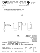
Expansion Tanks
Designed to isolate circulator pumps to facilitate circulator pump replacement or repairs.
Series IPF
Isolation Pump Flanges for Circulator Pumps
Sizes:
3
⁄4" – 2" (20 – 50mm)
Series IPF Isolation Pump Flanges are designed to isolate
circulator pumps to facilitate circulator pump replacement
or repairs.
Features
• Brass body and flange
• Adjustable Virgin PTFE packing
• Buna-N stem O-ring seal
• Supplied with lever handle
• Optional T-handle included
• Virgin PTFE seats
• Bottom loaded, blowout proof stem
Models
IPF-T-M1
3
⁄4" – 2" (20 – 50mm) NPT threaded end connection
IPF-S-M1
3
⁄4" – 2" (20 – 50mm) Solder end connection
Specifications
Maximum Working Pressure: 600psi (41.4 bar) WOG
Maximum Temperature: 406°F (208°C) at 100psi (6.9 bar)
For additional information, request literature ES-IPF-M1.
IPF
IPF
Typical Installation
D
F
E
Isolation Pump Flanges
IPF-S-M1
IPF-T-M1
(
3
⁄4" – 2")
(
3
⁄4" – 2")
C
A
G
B
Size Dimensions WEIGHT
(DN) A B C D E F G
in. mm in. mm in. mm in. mm in. mm in. mm in. mm in lbs. kg
IPF-T-M1
3
⁄4 20
3
⁄4 19 2
1
⁄4 54 3 77 3
3
⁄16 80 4
5
⁄8 118 2
11
⁄16 69
3
⁄4" NPT 1.3 .61
1251 25 2
5
⁄8 63 3 77 3
3
⁄16 80 4
5
⁄8 118 2
11
⁄16 69 1" NPT 1.6 .72
1
1
⁄4 32 1
1
⁄4 31 2
13
⁄16 72 4 107 3
3
⁄16 80 4
5
⁄8 118 2
11
⁄16 69 1
1
⁄4" NPT 2.1 .97
1
1
⁄2 40 1
1
⁄2 39 3
1
⁄4 79 4 107 3
3
⁄16 80 4
5
⁄8 118 2
11
⁄16 69 1
1
⁄2" NPT 2.5 1.13
2501
7
⁄8 47 3
3
⁄4 90 4 107 3
7
⁄16 87 4
5
⁄8 118 2
11
⁄16 69 2" NPT 2.5 1.16
IPF-S-M1
3
⁄4 20
3
⁄4 19 2
1
⁄8 54 3 77 3
3
⁄16 80 4
5
⁄8 118 2
11
⁄16 69 — 1.3 .60
1251 25 2
1
⁄2 63 3 77 3
3
⁄16 80 4
5
⁄8 118 2
11
⁄16 69 — 1.6 .72
1
1
⁄4 32 1
1
⁄4 31 2
13
⁄16 72 4 107 3
3
⁄16 80 4
5
⁄8 118 2
11
⁄16 69 — 2.1 .97
1
1
⁄2 40 1
1
⁄2 39 3
1
⁄8 79 4 107 3
3
⁄16 80 4
5
⁄8 118 2
11
⁄16 69 — 2.5 1.13
2501
7
⁄8 47 3
1
⁄2 90 4 107 3
7
⁄16 87 4
5
⁄8 118 2
11
⁄16 69 — 3.0 1.36
PG-HHS.qxd 8/13/08 10:10 AM Page 17

18
Expansion Tanks
Expansion Tanks
Series PIPF
Isolation Pump Flanges with Purge Port &
Swivel Flange
Sizes:
3
⁄4" – 1
1
⁄4" (20 – 32mm)
Series PIPF Isolation Pump Flanges with Purge Port & Swivel
Flange are designed to provide circulator pump isolation to facili-
tate the circulator pump replacement or repair while the integral
purge port facilitates system purging.
Features
• Ball valve isolation for circulator pumps
• Integral purge port saves time and money compared to purge
stations made with ball valves, boiler drains, and
copper tees
• Swivel flange allows purge port to be positioned for optimal
purging convenience
• Brass body and flange
• Pressure rated to 400psi (28 bar) WOG
• Double O-ring stem sealing technology eliminates packing leaks
• Bottom loaded, blowout, proof stem
Models
PIPF-T
3
⁄4" – 1
1
⁄4" (20-32mm) threaded NPT end connections
PIPF-S
3
⁄4" – 1
1
⁄4" (20-32mm) solder end connections
Specifications
Maximum Operating Temperature:
406°F (208°C) at 100psi (6.9 bar)
Pressure Rated: 400psi (28 bar) WOG
For additional information, request literature ES-PIPF.
PIPF-S
PIPF-T
PIPF
IPF
C
A
B
D
E
Isolation Pump Flanges
MODEL SIZE (DN) DIMENSIONS WEIGHT
ABC DE
in. mm in. mm in. mm in. mm in. mm in. mm lbs. kgs.
PIPF-T
3
⁄4 20
3
⁄4 19 3 76 2
15
⁄16 74 3
1
⁄8 79 4
1
⁄8 105 1.86 0.84
1 25 1 25 3
3
⁄8 86 2
15
⁄16 74 3
1
⁄8 79 4
1
⁄8 105 2.24 1.02
1
1
⁄4 32 1
1
⁄4 31 3
11
⁄16 93 4
1
⁄16 103 3
1
⁄8 79 4
1
⁄8 105 2.83 1.28
PIPF-S
3
⁄4 20
3
⁄4 19 3
1
⁄8 80 2
15
⁄16 74 3
1
⁄8 79 4
1
⁄8 105 1.71 0.77
1 25 1 25 3
1
⁄2 89 2
15
⁄16 74 3
1
⁄8 79 4
1
⁄8 105 1.99 0.90
1
1
⁄4 32 1
1
⁄4 31 3
13
⁄16 98 4
1
⁄16 103 3
1
⁄8 79 4
1
⁄8 105 2.43 1.10
Typical Installation
PG-HHS.qxd 8/13/08 10:10 AM Page 18
/