Page is loading ...

Model #: GWL-2300
Publication: 00007-AM-EN 2016-08-08
Global Wheel-Lok™ GWL-2300
Vehicle Restraint
Owner’s Manual
This manual covers units: built after serial numbers GW231001 and up
Installed on:
Language: English
The English version of this manual shall prevail over any
error in, or conicting interpretation of, any translations.
Notice to User. . . . . . . . . . . . . . . . . . . 2
Safety Identications . . . . . . . . . . . . . 3
Owner Responsibility . . . . . . . . . . . . . 6
Denition and Function. . . . . . . . . . . . 7
Features . . . . . . . . . . . . . . . . . . . . . . 8
Operating procedures. . . . . . . . . . . . 10
Maintenance. . . . . . . . . . . . . . . . . . . 15
Troubleshooting . . . . . . . . . . . . . . . . 17
Parts . . . . . . . . . . . . . . . . . . . . . . . . 28
Warranty . . . . . . . . . . . . . . . . . . . . . . 52

Global Wheel-Lok™ GWL-2300 Owner’s Manual Rite-Hite®
2 Publication: 00007-AM-EN 2016-08-08
NOTICE TO USER
Read and understand this manual before attempting
to install or operate. For best results, have this product
serviced by your authorized RITE-HITE® representative.
The GWL-2300 vehicle restraint by RITE-HITE is intended
to provide a safer workplace for workers in shipping and
receiving dock areas. The GWL-2300 vehicle restraint is a
restraint device that, when properly installed and operated,
retains a secure connection between the truck and dock.
Signal lights, warning horn and signs provide instructions
to the truck driver and GWL-2300 vehicle restraint operator
that a safe condition exists. The GWL-2300 vehicle
restraint is operated by pressing push buttons on an inside
control box.
Your local Rite-Hite® representative provides a Planned
Maintenance Program (P.M.P.) which can be tted to
your specic operation. Call your local representative or
Rite-Hite® at 414-355-2600.
The Rite-Hite® products in this manual are covered by one or more
of the following U.S. patents: 5882167, 6065172, 6070283, 6085375,
6092970, 6106212, 6116839, 6190109, 6276016, 6311352, 6318947,
6322310, 6360394, 6368043, 6431819, 6488464, 6524053, 6726432,
6773221, 6832403, 6880301, 7032267, 7062814, 7213285, 7216391,
7363670, 7380305, 7503089, 7533431, 7546655, 7584517, 7681271,
7823239, 7841823, 7877831, 7914042, 8006811, 8065770, 8141189,
8191194, 8286757, 8287223, 8303235, 8307956, 8443474, 8464384,
8464846, 8465245, 8497761, 8499897, 8544130, 8547234, 8590087,
8590673, 8616826, 8657551, 8662535, 8678736, 8690087, 8905198,
9010501, 9096170, 9096397, 9126775, 9139384, 9145273, 9150367,
9174811, 9227799, 9230419 and may be covered by additional pending
U.S. and foreign patent applications.
RITE-HITE®, THINMANTM, SAFE-T-LIP®, HYDRACHEK®, WHEEL-
LOKTM, DOK-LOK®, DUAL-DOK®, SAFE-T-STRUTTM, DOK-
COMMANDER®, JUMBOTM, HYDRA-RITETM, SAFE-T-GATE®,
RITE-VUTM LIGHT COMMUNICATION SYSTEM and SMOOTH
TRANSITION DOK SYSTEM™, are trademarks of Rite-Hite®.
FCC Compliance
NOTE: This equipment has been tested and found to comply with the
limits for a Class A digital device, pursuant to Part 15 of the FCC Rules.
These limits are designed to provide reasonable protection against
harmful interference when the equipment is operated in a commercial
environment. This equipment generates, uses, and can radiate radio
frequency energy and, if not installed and used in accordance with
the instruction manual, may cause harmful interference to radio
communications. Operation of this equipment in a residential area
is likely to cause harmful interference in which case the user will be
required to correct the interference at his own expense.
NOTE: Changes or modifications not expressly approved by the party
responsible for compliance could void the use's authority to operate the
equipment.
This device complies with Part 15 of the FCC Rules. Operation is subject
to the following two conditions:
(1) This device may not cause harmful interference
(2) This device must accept any interference received, including
interference that may cause undesirable operation.

Rite-Hite® Global Wheel-Lok™ GWL-2300 Owner’s Manual
Publication: 00007-AM-EN 2016-08-08 3
SAFETY IDENTIFICATIONS
! DANGER
Indicates a hazardous situation which, if not
avoided, will result in death or serious injury.
! WARNING
Indicates a hazardous situation which, if not
avoided, could result in death or serious injury.
! CAUTION
Indicates a hazardous situation which, if not
avoided, could result in minor or moderate injury.
NOTICE
Indicates a situation which can cause damage to the
equipment, personal property and/or the environment,
or cause the equipment to operate improperly.
NOTE:A note is used to inform you of important
installation, operation, or maintenance information.
! WARNING
When working with electrical or electronic
controls, make sure that the power source
has been locked out and tagged according to
regulations and approved local electrical codes.
DO NOT
OPERATE
Figure 1 - Lockout/Tagout

Global Wheel-Lok™ GWL-2300 Owner’s Manual Rite-Hite®
4 Publication: 00007-AM-EN 2016-08-08
NOTES

Rite-Hite® Global Wheel-Lok™ GWL-2300 Owner’s Manual
Publication: 00007-AM-EN 2016-08-08 5
NOTES

Global Wheel-Lok™ GWL-2300 Owner’s Manual Rite-Hite®
6 Publication: 00007-AM-EN 2016-08-08
OWNER RESPONSIBILITY
1. The owner should recognize the inherent danger of
the interface between dock and transport vehicle. The
owner should, therefore, train and instruct operators in
the safe use of dock equipment in accordance with the
information provided below. The manufacturer shall
publish, provide to the initial purchaser, and make the
following information readily available to owners:
• Installation instructions
• Recommended initial and periodic inspections
procedures
• Maintenance procedures
• Operating instructions
• Descriptions or specications for replaceable or
repairable parts
• Tables identifying the grade (slope) for all variations
of length or conguration of the dock equipment, and
• Information identifying the maximum uncontrolled
drop encountered upon sudden removal of support
while within the working range of the equipment.
It shall be the responsibility of the owner to verify that
the material listed in this section has been received
and that it is made available for the instruction
and training of personnel entrusted with the use or
maintenance of the dock equipment.
2. When a transport vehicle is parked at a loading
dock, it is important that the vehicle is relatively
perpendicular to the dock face and in close contact
with at least one of the dock bumpers.
3. Nameplates, cautions, instructions, and posted
warnings shall not be obscured from the view of
operating or maintenance personnel for whom such
warnings are intended.
4. Manufacturer’s recommended periodic maintenance
and inspection procedures in effect at date of
shipment shall be followed, and written records of the
performance of these procedures should be kept.
5. As with any piece of machinery, dock equipment
requires routine maintenance, lubrication, and
adjustments. Your local Rite-Hite representative offers
owners the option of a Planned Maintenance Program
(P.M.P.). As part of this service, your local Rite-Hite
representative will do all routine maintenance,
lubrication, and adjustments.
6. Dock equipment that is structurally damaged shall be
removed from service, inspected by a manufacturer’s
authorized representative, and repaired as needed
before being placed back in service.
7. The manufacturer shall make available replacement
nameplates, caution/instruction labels, and operating/
maintenance manuals upon request of the owner.
The owner shall see that all nameplates, caution/
instruction markings or labels are in place and legible,
and that the appropriate operating/maintenance
manuals are provided to users.
8. Modifications or alterations of dock equipment shall
be made only with written permission of the original
manufacturer. These changes shall also satisfy all
safety recommendations of the original equipment
manufacturer for the particular application of the dock
equipment.
9. In order to be entitled to the benefits of the standard
product warranty, the dock equipment must have
been properly installed, maintained and operated
within its rated capacities and/or specific design
parameters, and not otherwise abused.
10. It is recommended that trailers equipped with air
ride suspensions should remove the air from the
suspension to minimize trailer bed drop, prior to
loading or unloading.
11. When industrial trucks are driven on and off transport
vehicles during the loading and unloading operation,
the brakes on the transport vehicle shall be applied
and wheel chocks or a positive restraining device
shall be engaged.
12. It is recommended that an adequate stabilizing device
or devices be employed at the front of the trailer in all
cases where a trailer is being loaded or unloaded with
the trailer resting on its support legs (landing gear)
rather than a tractor fifth wheel or a converter dolly.
13. In selecting dock equipment, it is important to consider
not only present requirements but also future plans or
adverse environments.

Rite-Hite® Global Wheel-Lok™ GWL-2300 Owner’s Manual
Publication: 00007-AM-EN 2016-08-08 7
DEFINITION AND FUNCTION
The GWL-2300 vehicle restraint is a truck and trailer
locking system used to help secure trucks and trailers to
the face of a loading dock. The engagement mechanism is
positioned by the trailer as it approaches the loading dock.
The locking arm assembly, which blocks the rear wheel of
the truck or trailer, can then be engaged by pressing the
LOCK push button.
This prevents forward movement of the truck/trailer that
may create an unsafe void between the face of the dock
and the rear end of the truck/trailer as the forklift travels
from the loading dock onto the trailer; and creates an
obstruction noticeable (via outside lights) to the truck
driver, should the driver accidentally try to pull the truck/
trailer away while it is being serviced.
NOTE:There is no need to hold button to maintain its
function. Once a button is depressed, the GWL-2300
vehicle restraint will lock or unlock for a preset time interval.
The normal mode of the restraint is the locking arm
assembly stored at the far end (away from the dock) with
the barrier arm on the approach. Inside lights should be
on red and outside lights should be on green.
The proper activation of the barrier and the locking
mechanism is monitored by:
Visual Control
One set of green and red lights located inside the building
for the dock personnel, and one set located outside the
building for the truck driver. See Figure 2.
Audio Control
A horn will sound at the inside of the building, warning
the forklift operator if there is no R.I.G. present, or if the
engagement is improper. In this case, the trailer must
be secured by other means (wheel chocks, etc.) prior to
servicing trailer. See Figure 3.
Outside Light Box
With Red And
Green Lights
Inside Control Box
With Red And
Green Lights
Inside Control Box with
Red and Green Lights
Outside Light Box
with Red and
Green Lights
FIGURE 2 - VISUAL CONTROLS
FIGURE 3 - AUDIO CONTROLS

Global Wheel-Lok™ GWL-2300 Owner’s Manual Rite-Hite®
8 Publication: 00007-AM-EN 2016-08-08
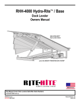
FEATURES
See Figure 3 for locations of these features.
Hydraulic Cylinder
Moves the Lifting Rails back and forth, thus raising or
lowering the locking pawl into place.
Barrier Shaft
The shaft which serves as the restraining obstruction in
front of the rearmost tire. It is connected to the locking arm
assembly.
Barrier Ramp
The assembly that the barrier shaft stores in. Barrier ramp
is used to protect the barrier shaft when a truck/trailer
backs into place.
Frame Assembly
The main weldment which is bolted onto the approach. It
acts as a guide/rail for the locking arm assembly, trigger
trolley, and lock trolley.
Locking Arm Assembly
The assembly which is rotated up into its UP position
when a trailer backs into the dock.
Locking Arm Trolley Assembly
Locking arm trolley assembly holds the locking arm
assembly to the frame and houses the pawl assembly.
Lifting Rails
The component which is pushed by the hydraulic cylinder.
It rides upon diagonal slotted plates along the frame. The
vertical motion drives the locking pawl into the ratchet.
Pawl Assembly
Assembly which is driven upward into the ratchet by the
Lifting Rails when the unit is locked.
Trigger Assembly
Component which is contacted by the rearmost tire of
a trailer. When a tire engages the trigger, it will pull the
locking arm assembly into its UP position, and pull the
locking arm assembly along the frame assembly.
Trigger Trolley Assembly
The trigger trolley assembly holds the trigger assembly to
the frame.
Extension Springs
The extension springs connect the locking arm trolley to
the trigger trolley.
Lock Sensor (SW1)
Communicates to the control box whether or not the unit is
locked. (Not shown, See pages 24 & 26)
Unlock Sensor (SW2)
Communicates to the control box whether or not the unit is
unlocked. (Not shown, See pages 24 & 26)
PAWL HOLD DOWN
Mechanically senses if a trailer tire is present when the
locking arm is raised.
Control Box, Outside Light Box, and Signage
The combination of these components are uses to control
the function of the GWL-2300 Wheel Restraint and provide
audio/visual communication to the dock attendant and the
trailer driver.

Rite-Hite® Global Wheel-Lok™ GWL-2300 Owner’s Manual
Publication: 00007-AM-EN 2016-08-08 9
Control
Box
Outside
Signs
Maintenance
Strut
Power Unit
Enclosure
Frame
Assembly
Lifting Rails
Hydraulic
Cylinder
Trigger
Assembly
Barrier
Ramp
Locking Arm
Assembly
Barrier Shaft
Pawl
Assembly
Locking Arm
Trolley Assembly
Trigger Trolley
Assembly
Side
Covers
Inside
Sign Anchor
Kit
Outside
Lights
Maintenance Strut
Storage Hooks
Extension Springs
Pawl
Hold Down
FIGURE 4 - FEATURES OF GWL-2300
FEATURES
Inside
Caution Sign
Outside
Caution Signs
Anchor Kit
Outside
Light Box
Control Box
Barrier Ramp
Trigger
Assembly
Trigger Trolley
Assembly
Pawl Hold
Down
Hydraulic
Cylinder
Lifting Rails
Power Unit
Enclosure
Frame Assembly
Side
Covers
Maintenance
Strut
Lock Arm
Assembly
Barrier Shaft
Pawl Assembly
Locking Arm
Trolley Assembly
Maintenance Strut
Storage Hooks
Extension Springs

Global Wheel-Lok™ GWL-2300 Owner’s Manual Rite-Hite®
10 Publication: 00007-AM-EN 2016-08-08
OPERATING PROCEDURES
Stored Position / Restraint UNLOCKED
If the GWL-2300 vehicle restraint is in the UNLOCKED
position (shaft assembly is down and stored in barrier
ramp), the Light Communication System should give the
following signals:
1. OUTSIDE light flashing GREEN, which indicates that
a vehicle may pull into or out of the loading bay.
2. INSIDE light flashing RED, which indicates that
loading or unloading is not permitted, since the truck
is not secured against the building. See Figure 5.
Restraint Locking, LOCK Button Pressed
It is assumed that the loading bay is empty (no truck).
The outside GREEN light and the inside RED light are
ashing, the barrier is down. A truck can now approach
the loading position. As the truck backs in, it will activate
the trigger, causing the locking arm to come up. The
mechanism will automatically adjust to the correct wheel
size. The truck will move locking arm and trolleys into
position automatically. When the truck is parked rmly
against the bumpers, the operator can lock the vehicle.
To lock the vehicle, the LOCK button must be depressed
momentarily. The outside light will change instantly from
GREEN to RED. The inside light will remain steady RED
until the locking mechanism is engaged properly. Once it
is engaged, the inside light will change to GREEN. The
truck may now be serviced. The light communication and
truck position are shown in Figure 6.
OUTSIDE LIGHT
STATUS
CONTROL BOX
STATUS
GWL-2300 POSITION
Outside Lights
Inside Lights
RED
GREEN
OUTSIDE LIGHTS
Check outside lights when
both LEDs are o.
UNLOCK
LOCK
1
3
2
HORN OVERRIDE
DOK-LOK®
DO NOT ENTER TRAILER
ENTER TRAILER
Visually inspect before loading/
unloading vehicle. DOK-LOK
hook must secure rear impact
guard. See warnings on side
panel.
Additional warning labels,
manuals and other information
are available by calling:
1-800-456-0600
If red light is on and/or horn
sounds, DOK-LOK is not
properly engaged.
Check operation of DOK-LOK.
Vehicle may not be against dock.
R.I.G. may not be compatible.
Hook travel may be obstructed.
Before using "HORN OVERRIDE,"
secure vehicle by other means.
Reset system by engaging "HORN
OVERRIDE" control again. Then repeat
"UNLOCK
" operation.
When in "HORN OVERRIDE" mode:
Both red and green Lights flash. "LOCK" and
"UNLOCK" controls are not functional.
Horn can be silenced by engaging
"HORN OVERRIDE" control.
Before using "HORN OVERRIDE," secure
vehicle by other means prior to entering.
If horn and red light are on
after "UNLOCK" control is
pressed, hook may be held
by R.I.G.
To release hook:
Back trailer up against dock.
Repeat "UNLOCK" operation.
FIGURE 5 - STORED POSITION, INSIDE RED LIGHT AND OUTSIDE GREEN LIGHT
GWL-2300 Control Box Status Outside Light
Status
Inside Lights Outside Lights

Rite-Hite® Global Wheel-Lok™ GWL-2300 Owner’s Manual
Publication: 00007-AM-EN 2016-08-08 11
OUTSIDE LIGHT
STATUS
CONTROL BOX
STATUS
GWL-2300 POSITION
GREEN
RED
OUTSIDE LIGHTS
Check outside lights when
both LEDs are o.
UNLOCK
LOCK
1
3
2
HORN OVERRIDE
DOK-LOK®
DO NOT ENTER TRAILER
ENTER TRAILER
Visually inspect before loading/
unloading vehicle. DOK-LOK
hook must secure rear impact
guard. See warnings on side
panel.
Additional warning labels,
manuals and other information
are available by calling:
1-800-456-0600
If red light is on and/or horn
sounds, DOK-LOK is not
properly engaged.
Check operation of DOK-LOK.
Vehicle may not be against dock.
R.I.G. may not be compatible.
Hook travel may be obstructed.
Before using "HORN OVERRIDE,"
secure vehicle by other means.
Reset system by engaging "HORN
OVERRIDE" control again. Then repeat
"UNLOCK
" operation.
When in "HORN OVERRIDE" mode:
Both red and green Lights flash. "LOCK" and
"UNLOCK" controls are not functional.
Horn can be silenced by engaging
"HORN OVERRIDE" control.
Before using "HORN OVERRIDE," secure
vehicle by other means prior to entering.
If horn and red light are on
after "UNLOCK" control is
pressed, hook may be held
by R.I.G.
To release hook:
Back trailer up against dock.
Repeat "UNLOCK" operation.
Outside Lights
Inside Lights
FIGURE 6 - TRUCK LOCKED AGAINST THE BUMPERS
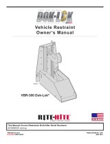
OPERATING PROCEDURES
Restraint LOCKED
If the GWL-2300 vehicle restraint is in the LOCKED
position with the barrier up and the locking mechanism
engaged properly, the Light Communication System
should give the following signals:
1. OUTSIDE light flashing RED, indicating that the truck
driver is not permitted to leave.
2. INSIDE light flashing is GREEN, indicating that the
truck may now be loaded or unloaded. See Figure 6.
NOTE:If testing without a trailer present, make sure
to manually separate trollies so pawl hold down is
disengaged.
Restraint UNLOCKING, UNLOCK Button
Pressed
In order to release the truck after completion of the
loading/unloading process, the UNLOCK pushbutton must
be pressed. The inside light will turn instantly to steady
RED, while the outside light remains ashing RED until the
locking mechanism is disengaged. The outside light will
turn to ashing GREEN, allowing the truck to depart. The
truck will automatically move the locking arm to the stored
position when departing.
NOTICE
On occasion the truck/trailer may move forward during
servicing putting pressure on the pawl assembly. If an
unlock “Fault” occurs the truck/trailer may need to be
positioned rmly against the dock bumpers to release
the pressure on the pawl assembly.
FIGURE 6 - TRUCK LOCKED AGAINST THE BUMPERS
Control Box
Status
Outside Light
Status
INSIDE LIGHTS OUTSIDE
LIGHTS
GWL-2300

Global Wheel-Lok™ GWL-2300 Owner’s Manual Rite-Hite®
12 Publication: 00007-AM-EN 2016-08-08
OPERATING PROCEDURES
FAULT State from LOCKING State
In case the locking mechanism can not engage properly,
the alarm will sound. The outside and inside lights will
show ashing RED. The light communication, alarm and
truck position are shown in Figure 7.
HORN OVERRIDE State, HORN OVERRIDE
Code Entered or HORN OVERRIDE Button
Pressed after Securing Trailer by
Alternate Means
! DANGER
Before operating “HORN OVERRIDE”, secure
trailer by other means.
The horn may be silenced AFTER the trailer has been
secured by other means. This can be done by entering the
horn silence code. Both inside lights will now ash (red
and green) and all control buttons are inactive. See Figure
8. Once service is completed, enter the horn silence code
and press the unlock push button. The truck/trailer may
now depart once GWL-2300 unlocks.
OUTSIDE LIGHT
STATUS
CONTROL BOX
STATUS
GWL-2300 POSITION
GREEN
RED
Outside Lights
Horn
Inside Lights
OUTSIDE LIGHTS
Check outside lights when
both LEDs are o.
UNLOCK
LOCK
1
3
2
HORN OVERRIDE
DOK-LOK®
DO NOT ENTER TRAILER
ENTER TRAILER
Visually inspect before loading/
unloading vehicle. DOK-LOK
hook must secure rear impact
guard. See warnings on side
panel.
Additional warning labels,
manuals and other information
are available by calling:
1-800-456-0600
If red light is on and/or horn
sounds, DOK-LOK is not
properly engaged.
Check operation of DOK-LOK.
Vehicle may not be against dock.
R.I.G. may not be compatible.
Hook travel may be obstructed.
Before using "HORN OVERRIDE,"
secure vehicle by other means.
Reset system by engaging "HORN
OVERRIDE" control again. Then repeat
"UNLOCK
" operation.
When in "HORN OVERRIDE" mode:
Both red and green Lights flash. "LOCK" and
"UNLOCK" controls are not functional.
Horn can be silenced by engaging
"HORN OVERRIDE" control.
Before using "HORN OVERRIDE," secure
vehicle by other means prior to entering.
If horn and red light are on
after "UNLOCK" control is
pressed, hook may be held
by R.I.G.
To release hook:
Back trailer up against dock.
Repeat "UNLOCK" operation.
FIGURE 7 - FAULT MODE, TRUCK NOT PROPERLY LOCKED, HORN ON
GWL-2300 Control Box Status Outside Light
Status
Inside Lights
Outside
Lights
Horn
OUTSIDE LIGHT
STATUS
CONTROL BOX
STATUS
GWL-2300 POSITION
GREEN
RED
Outside Lights
Inside Lights
OUTSIDE LIGHTS
Check outside lights when
both LEDs are o.
UNLOCK
LOCK
1
3
2
HORN OVERRIDE
DOK-LOK®
DO NOT ENTER TRAILER
ENTER TRAILER
Visually inspect before loading/
unloading vehicle. DOK-LOK
hook must secure rear impact
guard. See warnings on side
panel.
Additional warning labels,
manuals and other information
are available by calling:
1-800-456-0600
If red light is on and/or horn
sounds, DOK-LOK is not
properly engaged.
Check operation of DOK-LOK.
Vehicle may not be against dock.
R.I.G. may not be compatible.
Hook travel may be obstructed.
Before using "HORN OVERRIDE,"
secure vehicle by other means.
Reset system by engaging "HORN
OVERRIDE" control again. Then repeat
"UNLOCK
" operation.
When in "HORN OVERRIDE" mode:
Both red and green Lights flash. "LOCK" and
"UNLOCK" controls are not functional.
Horn can be silenced by engaging
"HORN OVERRIDE" control.
Before using "HORN OVERRIDE," secure
vehicle by other means prior to entering.
If horn and red light are on
after "UNLOCK" control is
pressed, hook may be held
by R.I.G.
To release hook:
Back trailer up against dock.
Repeat "UNLOCK" operation.
FIGURE 8 - FAULT MODE, TRUCK NOT PROPERLY LOCKED, HORN SILENCED
Inside Lights
Outside
Lights
Control Box Status Outside Light
Status
GWL-2300

Rite-Hite® Global Wheel-Lok™ GWL-2300 Owner’s Manual
Publication: 00007-AM-EN 2016-08-08 13
OPERATING PROCEDURES
Vehicle Release During Loss of Power
! CAUTION
Do not remove lock arm when a truck tire is present.
During loss of power, the GWL-2300 vehicle restraint will
not automatically disengage the vehicle being serviced.
The truck must be manually released by the following
method. See Figures 9.
FIGURE 9 - MANUALLY RELEASING TRUCK
Remove
Pin
Lifting Rail
Procedure
1. Lockout/Tagout controls.
2. Remove pin which connects the hydraulic cylinder to
the Lifting Rails. See Figure 9.
3. Place pry bar in hole between end of lifting rail and
frame hole as shown in figure 10. Pry away from the
dock, lowering the lifting rails and disengaging the
locking pawl.
4. Do not use equipment until reassembled.
FIGURE 10 - LOCK RAILS LOWERED
Place Pry Bar In Hole And
Pry Away From Dock

Global Wheel-Lok™ GWL-2300 Owner’s Manual Rite-Hite®
14 Publication: 00007-AM-EN 2016-08-08
OPERATING PROCEDURES
Snow Removal Procedure
! WARNING
Wheel guides, locking arm assembly, trigger, or
frame assembly may be buried underneath snow,
thus not visible. Unseen obstructions may cause
damage to equipment and/or bodily harm during
snow removal if they should come into contact
with the snow removal equipment.
In the event of snow fall, please follow the procedure
below to clear and remove snow from the truck approach.
Procedure
1. Using the service strut, move the locking arm
assembly all the way towards the dock face. See
Figure 11.
2. Back drag snow from the approach. Be sure not to
hit the wheel guides, locking arm assembly, trigger,
barrier ramp and frame assembly with the plow.
3. Return the locking arm assembly to the stored
position after completion of snow removal.
4. Remove snow against dock by alternate means
(shovel, snowblower, etc.).
5. Manually clean on and around unit to prevent ice
build-up.
Engage Locking Arm Assembly With Service Strut
Service
Strut
Move To Rearmost Position
Return To Stored Position
FIGURE 11 - SNOW REMOVAL
Service Strut
Engage Locking Arm Assembly with Service Strut
Move To Rearmost Position
Return to Stored Position
Recommended Liquid De-Icer:
Any Calcium-Chloride based liquid de-icer.

Rite-Hite® Global Wheel-Lok™ GWL-2300 Owner’s Manual
Publication: 00007-AM-EN 2016-08-08 15
MAINTENANCE
(Based on typical applications of 8 trucks per day)
! DANGER
When working with electrical or electronic
controls, make sure that the power source
has been locked out and tagged according to
approved local electrical codes.
Post safety warnings and barricade work area, at
dock level and at ground level, to prevent
unauthorized use of the dock position.
! WARNING
A safe work place requires all lights and the horn
to be working properly. DO NOT use DOK-LOK
vehicle restraint if parts are broken or missing.
NOTICE
Maintenance may be required more frequently
at loading docks exposed to harsh environments
(extreme climates, corrosive chemicals, frequency
of usage exceeding 8 trucks per day, etc.). Consult
RITE-HITE if these conditions exist for accelerated
maintenance requirements.
NOTE:Your local RITE-HITE® representative provides
a Planned Maintenance Program (P.M.P.) which can
be tted to your specic operation. Call your local
representative.
Daily
1. Remove dirt, snow, ice and debris around GWL-2300
vehicle restraint.
2. Verify inside, outside lights and horn are working.
3. Replace damaged or missing light bulbs and lenses.
4. Repair, remount, or replace outside and inside signs
as required.
5. Inspect dock bumpers. Missing bumpers must be
replaced.
90 Days
Grease Barrier Roller
At Fitting -
Use Mobilith SCH220
No. 2 Grease
Grease Rollers (8) At Fittings -
Use Mobilith SCH220
No. 2 Grease
Both Sides
Grease Trolley Pin
At Fitting -
Use Mobilith SCH220
No. 2 Grease
Lubricate Pawl Shaft & Lifting Rail Slots
Dry Lubricate Only - DO NOT USE Moly Based Grease
FIGURE 12 - LUBRICATION
A
B
C
D
1. Perform all Daily maintenance.
2. See Figure 12. Grease rollers at fittings located on
both sides of trolleys (8 places) (A), lock arm (B) and
barrier roller (C). Use Mobilith SHC220 No. 2 grease
or equivalent temperature range lithium based grease
(Two (2) to three (3) pumps with a grease gun).
3. Lubricate Pawl Guide Shaft and Lifting Rail Slots with
a Dry Spray Lubrican (D) with a Dry Spray Lubricant
DO NOT USE Moly-Based Grease.
4. Check the trigger and rollers for damage, ensure
rollers spin freely.
5. Check brushes on trolleys and replace as necessary.
6. Inspect outside junction box, light box and power unit
enclosure. They should be rigidly mounted. If loose or
damaged, inspect all wires and wire connections.
7. Inspect flexible conduit from GWL-2300 vehicle
restraint to junction box. Look for kinks, crushed
areas, etc.
8. Perform operational test after all maintenance repairs
are complete.

Global Wheel-Lok™ GWL-2300 Owner’s Manual Rite-Hite®
16 Publication: 00007-AM-EN 2016-08-08
MAINTENANCE
180 Days
1. Do all the Daily and 90 Day maintenance.
2. Tighten the anchor bolts to 100 ft-lbs.
3. Check barrier roller tube for damage.
4. Check if all the bolts on the UHMW strip are tight.
5. Manually push the locking arm weldment along the
length of the frame to verify smooth operation. If
sticky, check for proper lubrication.
360 Days
1. Do all Daily, 90 and 180 Day maintenance.
2. Operate unit in (5) different places to ensure the
locking mechanism engages properly.
3. Disassemble both the locking arm and trigger trollies
and inspect internal sliders for wear. Replace as
necessary. See Figure 13.
4. Inspect wear pads in locking arm assembly. See
Figure 13.
NOTICE
Dock equipment must be protected by 4in [100mm]
thick bumpers. WORN, TORN, LOOSE, OR MISSING
BUMPERS MUST BE REPLACED.
5. Inspect pawl mechanism for wear on sliders.
6. Inspect bronze tooth on locking pawl.
7. Verify decals are present and legible, replace as
required.
8. Inspect lifting rail bushings for wear and replace if
worn through to pin hole.
Frame
Wear Strips
Steel
Trolley Sliders
Wear Pads
Pawl
UHMW Blocks
And Slider
Bronze Tooth
Lifting Rail Bushing
5 ea. on Rail
Steel
Trolley Slider
Torque to 73 Ft-Lbs. (Typ.)
Both Trolley’s
NOTE: Use loctite on screw.
DO NOT over torque. T
orque
To 60 In-Lbs.
FIGURE 13 - INSPECTION
Note: Use Loctite on
screw. DO NOT over
torque. Torgue to 60
In-Lbs.
Wear Pads
Frame Wear
Strips
Bronze Tooth
Lifting Rail Bushing
5 places on Rail
Steel Trolley Sliders
Pawl UHMW
Blocks and Slider
Steel Trolley
Slider
Torque to 73 Ft-Lbs. (Typ.)
Both Trolley's)

Rite-Hite® Global Wheel-Lok™ GWL-2300 Owner’s Manual
Publication: 00007-AM-EN 2016-08-08 17
TROUBLESHOOTING
! DANGER
When working with electrical or electronic
controls, make sure that the power source has
been locked out and tagged according to OSHA
regulations and approved local electrical codes.
! WARNING
To prevent personal injury use extreme care when
working with electrically powered equipment.
Follow all safety instructions. Disconnect all
power, and keep body away from moving parts.
Use caution with compressed air; foreign
materials can be blown through the skin or into
the eyes. Use only approved air nozzles and do
not exceed recommended air pressure.
Problem Probable Cause Remedy
1. Cylinder does not
extend when LOCK
pushbutton is pushed
Main fuse blown Check motor fuse 10FU1.
Power unit power supply. Check voltage to transformer, bridge
rectier, etc.
Hydraulic system Check fluid level and hydraulic lines
for leaks.
2. No lights, but 120V
incoming power.
Blown power supply fuse Replace fuse. 11FU1
3. Unit goes into fault
about 8 seconds after
LOCK pushbutton is
pushed, with actuator
moving
Bad SW1 (Lock sensor). Replace SW1 (lock sensor).
SW1 wiring. Verify wiring per electrical schematic
on following pages.
Bronze “snaggle tooth” on pawl is damaged. Disassemble locking arm trolley and
replace snaggle tooth if required.
Barrier is to low, pawl is not engaging rack. Back trailer firmly against bumpers.
Trailer bogeys may be too far
forward to service.

Global Wheel-Lok™ GWL-2300 Owner’s Manual Rite-Hite®
18 Publication: 00007-AM-EN 2016-08-08
TROUBLESHOOTING
Sensing
Switch
Magnet
Blue
Wire
Brown
Wire
(LED Off)
(LED Off)
(LED On)
(LED On)
FIGURE 14 - SENSING SWITCH TEST AND SWITCH/BARRIER POSITION CHART
Sensing
Switch
Magnet
Black
White
Position Inside
Light
Outside
Light
Horn
Barrier SW1 SW2
1. Stored Open
No Magnet
(LED Off)
Closed
Magnet
(LED On)
Red Green Off
2. Fault Open
No Magnet
Open
No Magnet
Red Red On
3. Locked Closed
Magnet
(LED On)
Open
No Magnet
(LED Off)
Green Red Off
Sensing Switch Test Procedure
1. Set multimeter to “RX1” scale for “Continuity Test”
2. Attach multimeter leads to white and black wires of
mag. reed switch connector. You should have:
• Magnet present – a “Full Scale” meter reading.
• Magnet not present – no meter reading.
Motor Test Procedure
1. BAD O/L: Little or infinite ohm reading (no needle
movement) between lead 1 and 2, 1 and 3. Set
multimeter to ohms.
2. OPEN WINDING: Infinite ohms (no needle
movement) between lead 2 and 3. Check between
leads 1 and 2 or 1 and 3 to determine which winding
is open.
3. MECHANICAL BINDING: Motor hums. Motor leads
show continuity between all windings. Hydraulic
cylinder does not move.
multimeter
G
1
2
3
hydraulic power unit
FIGURE 15 - MOTOR TEST
Multi Meter
Hydraulic Power Unit

Rite-Hite® Global Wheel-Lok™ GWL-2300 Owner’s Manual
Publication: 00007-AM-EN 2016-08-08 19
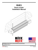
TROUBLESHOOTING
LED Status Chart
MICROCONTROLBOARD POWERBOARD
GWL‐2300
INPUTS OUTPUTS OUTPUTS
GLOBALWHEELLOK
FIELD PUSHBUTTONS 12VDC RELAY 115/230VAC
DOK‐LOKLIMITSWITCH1[SW1]
DOK‐LOKLIMITSWITCH2[SW2]
UNLOCKINTERLOCK[UNLKITL]
LOCKPUSHBUTTON
UNLOCKPUSHBUTTON
HORNSILENCEPUSHBUTTONS(1/2/3)
INSIDEREDLIGHT[ISR]
INSIDEGREENLIGHT[ISG]
CORNER‐VUREDLIGHT[CVURD]
CORNER‐VUGREENLIGHT[CVUGRN]
LEVELER‐VUREDLIGHT[LVURD]
LEVELER‐VUGREENLIGHT[L‐VUGRN]
OUTSIDEREDLIGHT[OSR]
OUTSIDEGREENLIGHT[OSG]
DOK‐LOKHORN[HORN]
RESTRAINTOVERLOADLED[YELLOW]
K1‐GREENLIGHTINTERLOCK
K2‐SECURITYSYSTEMINTERFACE
[IFEQUIPPED]
MOTOROUPTUT#1[M1/LOCK]
MOTOROUPTUT#2(M2/UNLOCK)
12VDCPOWERSUPPLYOK
TERMINALBLOCKNO.
J13.1 J13.2 J14.3MEMBRANE J7.16J7.17J12.1 J12.2 J12.3 J12.4 J11.2 J11.1 J7.19N/A J9.3 J10.3 J5.4 J5.3 J2.1‐6
POWERBOARDLEDs ‐‐‐‐‐‐‐‐‐‐‐‐‐‐‐‐‐‐LD2LD1LD7
MICROCONTROLBOARDLEDs LD20 LD23 LD30 LD52 LD17 LD19 LD11 LD13 LD18 LD12 LD49 LD48 LD15 LD50 LD9 LD10 LD1 LD3 ‐
01.01.00 LOCKEDSTATE TF?‐ ‐ ‐FPFPFPPFFFTTFFT
01.01.01 LOCKINGSEQUENCE FF?M‐ ‐TFPFPFPFFFFTTFT
01.02.00 UNLOCKEDSTATE FT? ‐ ‐ ‐PFPFPFFPFFFTFFT
01.02.01 UNLOCKINGSEQUENCE FFITL‐M‐TFPFPFPFFFFTFTT
01.04.00 FAULTSTATE ???‐ ‐ ‐PFPFPFPFPFFFFFT
01.04.01 FAULTSILENCEDSTATE ???‐ ‐MA A A PFFFTTFFT
01.11.00 OVERLOADFAULTSTATE ???‐ ‐ ‐PFPFPFPFKTFFFFT
NO. STATE/SEQUENCENO.
KEY
?‐VARYSDEPENDINGONOPERATION
K‐CONTINUOUSCHIRP
A‐ALTERNATING
M‐LIGHTSWHENBUTTONPRESSED
F‐OFF P‐PULSING/FLASHING[SETTOSTEADYUSINGDIPSWITCHES]
ITL‐INTERLOCKINPUTON
T‐STEADYON
MOTOROVERLOADRESETPROCEDURE
IfYellowLEDLD50isilluminatedandtheDok‐LokHornisChirping,systemisinanOverloadFaultState.
Toresetthemotoroverload:
1)PressandHornSilence#2ButtonuntilHornChirps(Approximately5Seconds).OR
2)PressandReleaseRestraintO/LButtononMicroControllerBoard.
Whenthemotoroverloadhasbeenreset,theYellowLD50LEDwillturnoffandnormaloperationresumes.
IfDok‐Lokmotorstilldoesnotrunafterresetttingtheoverload,checkMotorFuse10FU1.
GWL23

Global Wheel-Lok™ GWL-2300 Owner’s Manual Rite-Hite®
20 Publication: 00007-AM-EN 2016-08-08
TROUBLESHOOTING
LED Status Chart Continued
MICROCONTROLBOARD POWERBOARD
GWL‐2300
INPUTS OUTPUTS OUTPUTS
GLOBALWHEELLOK
PUSHBUTTONS 12VDC 115/230VAC
FILLMODE
LOCKPUSHBUTTON
UNLOCKPUSHBUTTON
HORNSILENCEPUSHBUTTON
INSIDERED
INSIDEGREEN
CORNER‐VURED
CORNER‐VUGREEN
LEVELER‐VURED
LEVELER‐VUGREEN
OUTSIDERED
OUTSIDEGREEN
RESTRAINTALARM
MOTOROUPTUT#1[M1/LOCK]
MOTOROUPTUT#2(M2/UNLOCK)
12VDCPOWERSUPPLYOK
TERMINALBLOCKNO.
MEMBRANE J7.16J7.17J12.1 J12.2 J12.3 J12.4 J11.2 J11.1 J7.19J5.4 J5.3 J2.1‐6
POWERBOARDLEDs ‐‐‐‐‐‐‐‐‐‐‐‐LD2LD1LD7
MICROCONTROLBOARDLEDs LD52 LD17 LD19 LD11 LD13 LD18 LD12 LD49 LD48 LD15 LD1 LD3 ‐
01.15.14 FILLMODESEQUENCE
‐‐‐TFTFTFPFCFFT
01.15.15 SERVICEMOTORUP
M‐ ‐ TFTFTFPFCTFT
01.15.16 SERVICEMOTORDOWN
‐M‐ TFTFTFPFCFTT
NO. STATE/SEQUENCENO.
KEY
C‐CHIRPONSTATEENTRY
P‐PULSING/FLASHING
F‐OFF
T‐STEADYON
GWL23FILL
/