Page is loading ...

Revision 2.1: November 11, 2003
ALN-H0626
MITSUBISHI ELECTRIC AUTOMATION, INC.
UNINTERRUPTIBLE POWER SUPPLY SYSTEM
2033C SERIES
OWNERS / TECHNICAL MANUAL

MITSUBISHI
ELECTRIC
2033C SERIES UPS
OWNERS / TECHNICAL MANUAL
Page Number:
i
MITSUBISHI ELECTRIC 2033C SERIES UPS
Preface

MITSUBISHI ELECTRIC 2033C SERIES UPS
MITSUBISHI
ELECTRIC
2033C SERIES UPS
OWNERS / TECHNICAL MANUAL
Page Number:
ii
TABLE OF CONTENTS
LIST OF TABLES ............................................................................................... iii
LIST OF FIGURES ............................................................................................. iv
HOW TO USE THIS MANUAL ............................................................................ v
1.0 INTRODUCTION ......................................................................................... 1-1
1.1 GENERAL..................................................................................................... 1-3
1.2 DEFINITIONS .............................................................................................. 1-4
1.3 OVERVIEW ................................................................................................. 1-5
1.4 SPECIFICATIONS ....................................................................................... 1-14
2.0 OPERATION CONTROLS AND INDICATORS .......................................... 2-1
2.1 LCD TOUCH PANEL MONITOR DISPLAY AND KEYPAD ......................... 2-1
2.2 EXTERNAL SIGNAL TERMINAL BLOCK .................................................... 2-5
2.3 EXTERNAL COMMUNICATION CONNECTOR ......................................... 2-8
3.0 INSTALLATION AND OPERATION ........................................................... 3-1
3.1 TRANSPORTATION AND INSTALLATION ............................................... 3-1
3.2 HANDLING ................................................................................................. 3-1
3.3 INSTALLATION PROCEDURE ................................................................... 3-2
3.4 PROCEDURE FOR CABLE CONNECTIONS ............................................. 3-3
3.5 OPERATING PROCEDURES .................................................................... 3-9
3.6 MAINTENANCE BYPASS SET-UP PROCEDURES .................................. 3-10
4.0 RESPONSE TO UPS FAILURE .................................................................. 4-1
5.0 PARTS REPLACEMENT ............................................................................ 5-1
6.0 FAULT CODES ........................................................................................... 6-1
7.0 WARRANTY & OUT OF WARRANTY SERVICE ....................................... 7-1

MITSUBISHI ELECTRIC 2033C SERIES UPS
MITSUBISHI
ELECTRIC
2033C SERIES UPS
OWNERS / TECHNICAL MANUAL
Page Number:
iii
List of Tables
Table 1.1 Power Specifications ................................................................... 1-14
Table 1.2 UPS Module Information.............................................................. 1-14
Table 1.3 Detail of Specifications ................................................................ 1-15
Table 1.4 Rating of Conductor and Fuses ................................................... 1-16
Table 3.1 How to Transport and Install the System..................................... 3-1
Table 3.2 List of UPS Weights (lb.).............................................................. 3-2
Table 3.3 Type and Number of Internal Battery .......................................... 3-2
Table 3.4 Recommended Cable Size and Torque Requirements .............. 3-4
Table 3.5 Crimp Type Compression Lug ..................................................... 3-4

MITSUBISHI ELECTRIC 2033C SERIES UPS
MITSUBISHI
ELECTRIC
2033C SERIES UPS
OWNERS / TECHNICAL MANUAL
Page Number:
iv
List of Figures
Figure 1.1 Single Line Diagram-Normal Operation ....................................... 1-5
Figure 1.2 Single Line Diagram-Bypass Operation....................................... 1-6
Figure 1.3 Single Line Diagram-Battery Operation ....................................... 1-7
Figure 1.4 Single Line Diagram - UPS on Maintenance Bypass Operation. . 1-7
Figure 1.5a UPS Parts Location (7.5-20kVA) ................................................. 1-9
Figure 1.5b UPS Parts Location (30kVA) ....................................................... 1-10
Figure 1.5c UPS Parts Location (40,50kVA) .................................................. 1-11
Figure 1.6 Display PCB DPAU-72 ............................................................... 1-11
Figure 1.7 External I/F PCB RYDR-X .......................................................... 1-11
Figure 1.8 Main Control PCB UPFR-K.......................................................... 1-12
Figure 2.1 Operation/Display Panel ............................................................. 2-1
Figure 2.2 MAIN MENU Screen ................................................................... 2-2
Figure 2.3 MEASURMENT Screens ............................................................ 2-2
Figure 2.4 DATE&CLOCK SETUP Screen .................................................. 2-4
Figure 2.5 External Signal Terminal Block ................................................... 2-5
Figure 2.6 External Signal Terminal Block ................................................... 2-5
Figure 2.7 Control Wiring for External Contacts ........................................... 2-6
Figure 2.8 Remote "Start" Contact Connections........................................... 2-7
Figure 2.9 External communication connector.............................................. 2-8
Figure 3.1 Handling ..................................................................................... 3-1
Figure 3.2 UPS Terminal Designation .......................................................... 3-5
Figure 3.3 Input / Output Power Terminals (7.5-20kVA) -............................. 3-6
Figure 3.4 Input / Output Power Terminals (30kVA) ................................... 3-7
Figure 3.5 Input / Output Power Terminals (40,50kVA) ............................... 3-8
Figure 3.6 EPO Button ................................................................................. 3-9

MITSUBISHI ELECTRIC 2033C SERIES UPS
MITSUBISHI
ELECTRIC
2033C SERIES UPS
OWNERS / TECHNICAL MANUAL
Page Number:
v
How to use this Manual
This manual is designed for ease of use, giving the user easy and quick reference to information.
This manual uses notice icons to draw attention to the user important information regarding the
safe operation and installation of the UPS. The notice icons used in this manual are explained
below, and should be taken into account and adhered to whenever they appear in the text of this
manual.
Warning: A warning notice icon conveys information provided to protect
the user and service personnel against hazards and/or possible equipment
damage.
Caution: A caution notice icon conveys information provided to protect
the user and service personnel against possible equipment damage.
Note: A Note notice icon indicates when the user should make a reference of
information regarding the UPS operation, load status and display status.
Such information is essential if Mitsubishi field service group assistance and
correspondence is required.
Safety Recommendations: If any problems are encountered while following this manual,
Mitsubishi field service group assistance and correspondence is recommended.

MITSUBISHI
ELECTRIC
2033C SERIES UPS
OWNERS / TECHNICAL MANUAL
Page Number:
1-1
MITSUBISHI ELECTRIC 2033C SERIES UPS
1.0 INTRODUCTION
The Mitsubishi Uninterruptible Power Supply (UPS) is designed to provide many years of reliable
power supply and protection from power failure, brown-outs, line noise and voltage transients. To
ensure optimum performance of the equipment, follow the manufacturer's instructions accordingly.
This manual contains descriptions for the installation and operation procedures of the UPS. Please
read this manual carefully and retain it for future reference.
This manual contains important instructions for the 2033C Series Uninterruptible Power Supply
Systems that should be adhered to during installation, operation and maintenance of the UPS and
batteries.
Lethal voltages exist within the equipment during operation.
Observe all warning and cautions in this manual.
Failure to comply may result in serious injury or death.
Obtain a qualified service for this equipment as per instructions.
IMPORTANT SAFETY INSTRUCTIONS
RETAIN THESE INSTRUCTIONS
WARNING 1

MITSUBISHI
ELECTRIC
2033C SERIES UPS
OWNERS / TECHNICAL MANUAL
Page Number:
1-2
MITSUBISHI ELECTRIC 2033C SERIES UPS
This UPS does not include an AC input circuit breaker (MCCB) to protect the
bypass and main input circuit. The AC input circuit breaker (MCCB) is to be field
supplied and installed. Circuit breaker (MCCB) specifications are as follows:
Capacity
(kVA)
AC input
Voltage (Vac)
AC input
Rating (Aac)
Recommended
Breaker (A)
7.5 208 23 30
10 208 30 35
15 208 45 60
20 208 61 75
30 208 91 125
40 208 121 150
50 208 151 200
AC output and DC input overcurrent protection and disconnection devices shall be field
supplied and installed.
WARNING 2

MITSUBISHI
ELECTRIC
2033C SERIES UPS
OWNERS / TECHNICAL MANUAL
Page Number:
1-3
MITSUBISHI ELECTRIC 2033C SERIES UPS
1.1 GENERAL
The Mitsubishi 2033C Series UPS is designed to provide continuous and clean electrical power to
a critical load. In the event of an input power failure, the UPS will supply power to the critical load
for the specified battery time.
If the input power is not restored promptly, backup power from the UPS battery permits the orderly
shutdown of equipment supported by the UPS. The UPS is simple to start up, operate and
maintain.
The 2033C Series UPS is available in seven (7) kVA sizes: 7.5, 10, 15, 20, 30, 40 and 50kVA.
Specifications for each kVA model appear in Section 1.4. Models up to 30kVA have batteries
included in the UPS module cabinet. 40kVA and 50kVA models have external batteries. The
principles of operation described herein are applicable to all models.
This manual provides an overview of the 2033C Series components and their functions. The
appearance and purpose of operator controls and indicators is described with procedures for
operation, start-up, shutdowjn and basic maintenance included.

MITSUBISHI ELECTRIC 2033C SERIES UPS
MITSUBISHI
ELECTRIC
2033C SERIES UPS
OWNERS / TECHNICAL MANUAL
Page Number:
1-4
1.2 Definitions
UNINTERRUPTIBLE POWER SUPPLY SYSTEM (UPS) - All components within the UPS
Module Cabinet and associated batteries which function as a system to provide continuous,
conditioned AC power to a load. This is sometimes referred to as the "System".
UPS MODULE CABINET - The metal enclosure which contains the Converter / Charger,
Inverter, Static Transfer Switch, Internal Bypass line, operator controls, batteries (up to 30kVA
models only) and internal control systems required to provide specified AC power to a load.
UPS MODULE - The Converter / Charger and Inverter assemblies which, under the direction of
the internal control system and operator controls, provide specified AC power to a load.
CONVERTER / CHARGER - The UPS components which contain the equipment and controls
necessary to convert input AC power to regulated DC power required for battery charging and
for supplying power to the Inverter.
INVERTER - The UPS components which contain the equipment and controls necessary to
convert DC power from the Converter / Charger, or the battery, to AC power required by the
critical load.
STATIC TRANSFER SWITCH - The device which connects the critical load to the bypass line
when the Inverter cannot supply continuous power.
BYPASS LINE - The line which conducts electricity directly from the input power source to the
critical load during Maintenance or whenever the UPS is not completely operational.
AC INPUT POWER - Power provided by the electrical utility company, or auxiliary generator,
which is connected to the UPS for supplying the critical load and recharging the battery.
BATTERY - The rechargeable battery strings which supply DC power to the inverter to
maintain continuous AC power to the load during AC input power failure conditions.

MITSUBISHI ELECTRIC 2033C SERIES UPS
MITSUBISHI
ELECTRIC
2033C SERIES UPS
OWNERS / TECHNICAL MANUAL
Page Number:
1-5
1.3 Overview
The UPS provides two power paths between the utility source and the critical load. Figure 1.1
shows the path for normal operation, with the load powered from the inverter. Figure 1.2 shows
the path for bypass operation, with the load supplied through the static bypass line.
FIGURE 1.1 Single Line Diagram - Normal Operation. Load powered by inverter.
During normal operation, the path through the inverter is used to power the load.
Referring to Figure 1.1: Input AC power is converted to DC by the Converter. DC power is utilized to
charge the UPS battery and to provide power to the Inverter. The Inverter converts the DC power to
clean AC power to supply the critical load.
The conversion - inversion process eliminates any voltage transients or fluctuations existing in the
input power before it reaches the critical load.
* The Input circuit breaker(MCCB) for protection of the UPS and cables are field supplied and field
installed. (See WARNING 2 in section 1.0).
UPS Module
Static Transfer
Switch
Power Flow
Not in Use
AC input
CB
FB
CB2
CB3
CONVERTER INVERTER
Output
52C
CB1
FI
FO
BATTERY
User
su
pp
lied
52CS(7.5-20kVA)
52MB&52L(30-50kVA)
Maintenance
Bypass
Switch
40kVA, 50kVA:
External Battery

MITSUBISHI ELECTRIC 2033C SERIES UPS
MITSUBISHI
ELECTRIC
2033C SERIES UPS
OWNERS / TECHNICAL MANUAL
Page Number:
1-6
FIGURE 1.2 Single Line Diagram - Bypass Operation. Load fed through static bypass line.
Referring to Figure 1.2, the Internal Static Bypass line is a Hard wired line through CB3 which
supplies the critical load with unconditioned input power. The purpose of this line is to route power
to the critical load while the UPS module is de-energized (converter and inverter), and during
Start-up before the system is fully operational.
The internal control system determines the operation of the two paths, with the load powered from
the inverter being the normal operation.
Referring to Figure 1.3, if the input power is interrupted, the battery will immediately supply the DC
power required by the Inverter to maintain continuous AC power to the load. A fully charged battery
will provide power for the specified time at the rated load, or longer at reduced load.
When power is restored after a low battery shutdown, the Converter automatically restarts operation,
recharges the batteries and the Inverter is automatically restarted without operator intervention. The
load is assumed by the inverter automatically without operator intervention.
In the event of a power failure, the Converter will de-energize and the batteries will discharge into
the Inverter and maintain power to the critical load until a) the battery capacity expires and the
inverter turns off, or b) input power is restored after which the converter will power the inverter and
simultaneously recharge the batteries. Figure 1.3 illustrates the flow diagram during battery
operation.
Maintenance
Bypass
Switch
FB
BATTERY
CB2
CB3
Static Transfer
Switch
Power Flow
Not in Use
Output
52C
CB1
FI
FO
AC input
CB
User
su
pp
lied
CONVERTER
INVERTER
UPS Module
40kVA, 50kVA:
External Battery
52CS(7.5-20kVA)
52MB&52L(30-50kVA)

MITSUBISHI ELECTRIC 2033C SERIES UPS
MITSUBISHI
ELECTRIC
2033C SERIES UPS
OWNERS / TECHNICAL MANUAL
Page Number:
1-7
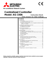
FIGURE 1.3 Single Line Diagram - Battery Operation
The UPS is equipped with an internal rotary type Maintenance Bypass Switch (MBS) that can be
used to divert utility power to the load during maintenance sessions. Figure 1.4 illustrates the power
path when the MBS is in the BYPASS mode.
FIGURE 1.4 Single Line Diagram - UPS on Maintenance Bypass Operation.
(7.5/10/15/20kVA)
The rotary maintenance bypass switch is shown as 52CS in Figure 1.4. 52CS is a two position
three point make-before-break transfer switch.
(30/40/50kVA)
Two contactors (52MB, 52L) are used instead of the 52CS. A rotary switch(SWM) is used for
control of the two contactors.
UPS Module
FB
BATTERY
CB2
CB3
Static Transfer
Switch
Power Flow
Not in Use
Output
52C
CB1
FI
FO
AC input
CB
User
su
pp
lied
CONVERTER
INVERTER
Maintenance
Bypass
Switch
40kVA, 50kVA:
External Battery
52CS(7.5-20kVA)
52MB&52L(30-50kVA)
UPS Module
FB
BATTERY
CB2
CB3
Static Transfer
Switch
Power Flow
Not in Use
52C
FO
CONVERTER
INVERTER
Output
AC input
CB
User
su
pp
lied
Maintenance
Bypass
Switch
CB1
FI
40kVA, 50kVA:
External Battery
52CS(7.5-20kVA)
52MB&52L(30-50kVA)

MITSUBISHI ELECTRIC 2033C SERIES UPS
MITSUBISHI
ELECTRIC
2033C SERIES UPS
OWNERS / TECHNICAL MANUAL
Page Number:
1-8
The two positions are identified as NORMAL and BYPASS. In the NORMAL position the load is fed
by the UPS - either through the inverter or through the static bypass line. In the BYPASS position
the load is powered by an external source such as the utility or a generator. This transfer operation
must be made while the UPS is in the static bypass mode.
The transfer procedure to place the UPS in maintenance bypass mode, or from bypass mode to
normal operation mode is outlined below:
A) Transfer of load from inverter to maintenance bypass
1. On the front panel, press the "STOP" button. The “BYP.OP.” LED illuminates within 3
seconds.
2. After confirming that the “BYP.OP.” LED is illuminated, Rotate MBS(52CS/SWM) clockwise
to the “TRANSFER” position (Do not rotate 52CS/SWM if the “BYP.OP.” LED is NOT
illuminated).
3. After 3 seconds, rotate 52CS/SWM clockwise to the “BYPASS” position.
4. Transfer complete. Load is now powered from the external source. UPS can be shutdown.
B) Transfer of load from maintenance bypass to inverter
1. Rotate 52CS/SWM counterclockwise from the “BYPASS” position to the “TRANSFER”
position, wait 5 seconds.
2. On the UPS, confirm the “BYP.OP.” LED is illuminated. If not, press the “STOP” button.
3. Rotate 52CS/SWM counterclockwise to the “NORMAL” position.
4. On the UPS, press the “START” button. The “INV.OP.” LED should illuminate.
5. Transfer complete. Load now powered by the inverter.

MITSUBISHI ELECTRIC 2033C SERIES UPS
MITSUBISHI
ELECTRIC
2033C SERIES UPS
OWNERS / TECHNICAL MANUAL
Page Number:
1-9
FIGURE 1.5a UPS Parts Location(7.5-20kVA)
4.Main PCB
UPFR-K
3.Relay PCB
RYDR-X
UPS module
FRONT VIEW
7.Maintenance bypass
transfer switch
52CS
Battery
5.AC input, AC
output terminal
Cooling fan
6.Grounding bar
Converter &
Inverter Uni
t
2.Display PCB
DPAU-72
1.LCD touch panel
monitor display

MITSUBISHI ELECTRIC 2033C SERIES UPS
MITSUBISHI
ELECTRIC
2033C SERIES UPS
OWNERS / TECHNICAL MANUAL
Page Number:
1-10
FIGURE 1.5b UPS Parts Location(30kVA)
4.Main PCB
UPFR-K
3.Relay PCB
RYDR-X
UPS module
FRONT VIEW
7.Maintenance bypass
transfer switch
SWM
Battery
5.AC input, AC
output terminal
Cooling fan
2.Display PCB
DPAU-72
6.Grounding
bar
Converter &
Inverter Uni
t
1.LCD touch panel
monitor display

MITSUBISHI ELECTRIC 2033C SERIES UPS
MITSUBISHI
ELECTRIC
2033C SERIES UPS
OWNERS / TECHNICAL MANUAL
Page Number:
1-11
FIGURE 1.5c UPS Parts Location(40,50kVA)
FIGURE 1.6 Display PCB DPAU-72
FIGURE 1.7 External I/F PCB RYDR-X
DPAU-57
DPAU-72
8.SW5
TEST switch
RYDR-X
10.CN62 RS232C
D-sub Connector
9.External contact
si
g
nal terminal block
11.CN64 RS232C
D-sub Connector
4.Main PCB
UPFR-K
UPS module
FRONT VIEW
Converter &
Inverter Uni
t
7.Maintenance bypass
transfer switch SWM
5.AC input, AC output
terminal
Cooling fan
2.Display PCB
DPAU-72
6.Grounding bar
3.Relay PCB
RYDR-X
1.LCD touch pane
monitor display

MITSUBISHI ELECTRIC 2033C SERIES UPS
MITSUBISHI
ELECTRIC
2033C SERIES UPS
OWNERS / TECHNICAL MANUAL
Page Number:
1-12
FIGURE 1.8 Main control PCB UPFR-K
Description of UPS parts, referred to in Figure 1.5:
1. LCD Touch Panel Monitor Display
The Liquid Crystal Display (LCD) Touch Panel Monitor Display indicates power flow, measured
values and fault and error messages via user selectable display screens.
2. Display PCB DPAU-72
Switches on DPAU-72 board : FOR SERVICE PERSONNEL ONLY (Figure 1.6):
- (8) SW5 (TEST switch)
3. Relay PCB RYDR-X board
Signal I/F on RYDR-X board : (Figure 1.7):
- (9) External contact signal terminal block
- (10) CN62 (RS232C communication connector)
- (11) CN64 (RS232C communication connector)
4. Main PCB UPFR-K
Switches on UPFR-K board : FOR SERVICE PERSONNEL ONLY (Figure 1.8):
- (8) SW11 (TEST switch)
- (12) SW13 (BOOT switch).
- (13) SW14 (RESET switch)
5. AC input, AC output terminal
Refer to Figure 3.3 for details
6. Grounding bar (E)
UPFR-K
12.SW13
BOOT switch
13.SW14
RESET switch
8.SW11
TEST switch

MITSUBISHI ELECTRIC 2033C SERIES UPS
MITSUBISHI
ELECTRIC
2033C SERIES UPS
OWNERS / TECHNICAL MANUAL
Page Number:
1-13
7. Maintenance Bypass Switch (52CS/SWM) (FOR SERVICE PERSONNEL ONLY) This switch
is used to transfer the load from inverter power to external power for maintenance purposes.
Do not operate it under normal operation.
8. "Test mode" switch (FOR SERVICE PERSONNEL ONLY)
This switch changes system operation to the test-mode. This switch is mounted on Display
PCB and Main PCB. (This switch should not be operated by personnel other than an
Authorized Service Engineer).
9. External contact signal terminal block
Terminal block to connect contact signal input/output lines to and from external dry contacts.
Refer to FIGURE 2.3 for details.
10. RS232C connector (CN62)
Refer to Figure 2.6 for detail.
11. RS232C connector (CN64)
12. "BOOT" switch (FOR SERVICE PERSONNEL ONLY)
This switch boots the processor on the main control circuit board following alarm conditions.
(Do not operate this switch while inverter and converter are in operation).
13. "Reset" switch (FOR SERVICE PERSONNEL ONLY)
This switch resets errors resulting from alarm conditions. (Do not operate this switch while
inverter and converter are in operation).

MITSUBISHI ELECTRIC 2033C SERIES UPS
MITSUBISHI
ELECTRIC
2033C SERIES UPS
OWNERS / TECHNICAL MANUAL
Page Number:
1-14
1.4 Specifications
The UPS name plate displays the rated kVA as well as nominal voltages and currents. The
name plate is located on the interior side of the UPS front door.
TABLE 1.1 Power Specifications
Rated output
Power
Input voltage
3 phase / 4 wire
Output voltage
3 phase / 3 or 4 wire
7.5kVA/6kW
10kVA/8kW
15kVA/12kW
20kVA/16kW
30kVA/24kW
40kVA/32kW
50kVA/40kW
208
208
208
208
208
208
208
208
208
208
208
208
208
208
TABLE 1.2 UPS Module Information
UPS
(kVA)
CABLE
ENTRY
WIDTH
(in/mm)
DEPTH
(in/mm)
HEIGHT
(in/mm)
WEIGHT
(lb./kg)
HEAT LOSS
@ 208V
(kBTU/h)
7.5 BOTTOM 17.7 / 450 31.5 / 800 43.3 / 1100 562 / 255* 3.2
10 BOTTOM 17.7 / 450 31.5 / 800 43.3 / 1100 562 / 255* 3.9
15 BOTTOM 17.7 / 450 31.5 / 800 43.3 / 1100 816 / 370* 5.1
20 BOTTOM 17.7 / 450 31.5 / 800 43.3 / 1100 816 / 370* 6.5
30 BOTTOM 23.6 / 600 31.5 / 800 59.0 / 1500 1235 / 560* 8.8
40 BOTTOM 27.6 / 700 31.5 / 800 59.0 / 1500 1082 / 490 11.9
50 BOTTOM 27.6 / 700 31.5 / 800 59.0 / 1500 1082 / 490 14.6
*:7.5-30kVA Including batteries
/