Page is loading ...

Actual product may differ from product pictured above
AASSSSEEMMBBLLYY IINNSSTTRRUUCCTTIIOONNSS
OOPPEERRAATTOORR''SS MMAANNUUAALL
PPAARRTTSS LLIISSTT
Models covered:
Blower Kit P/N 7078273
Bagger Kit P/N 0-50576
Weight Kit P/N 7078274
Complete Kit P/N 7063375
ZZ
--VVAACC
Grass Catcher Kit
for CZT/HZT
Series 0
Manual No. 7100056 (I.R. 03/31/05)

1
preliminaries
CCoonnggrraattuullaattiioonnss!!
You have just purchased one of the finest pieces of outdoor power equipment on the market today. If properly cared for,
your new Z-Vac Grass Catcher Kit will provide years of dependable service. Please read and follow this instruction man-
ual carefully in order to get the most out of your new equipment.
As you carefully unpack your unit, you will find the following items:
1 Blower Kit
1 Bagger Kit
1 Weight Kit
1 Package containing operating manuals and warranty registration
Each product leaves our factory in excellent condition; occasionally, however, some damage may occur during shipment.
If any such damage is found upon initial inspection, immediately notify the transport carrier who delivered your machine,
as they are solely responsible for such damage, as well as any subsequent adjustments necessary.
Before assembly, please take a moment and record your model number and serial number below for future reference (both
numbers are located on the serial tag attached to the blower):
Model number_______________________________
Serial number________________________________
Also be sure to promptly fill out and return the warranty registration enclosed in your manual packet.
Your new unit requires very little assembly. Simply follow the instructions contained within this manual to begin enjoying
the benefits of your new unit.
2

safety rules regarding outdoor power equipment
2
TRAINING
-- Read, understand, and follow all instructions in the man-
ual and on the unit before starting. If the operator(s) or
mechanic(s) can not read English it is the owner's responsi-
bility to explain this material to them.
-- Become familiar with the safe operation of the equipment,
operator controls, and safety signs.
-- All operators and mechanics should be trained. The
owner is responsible for training the users.
-- Only allow responsible adults, who are familiar with the
instructions, to operate the unit.
-- Never let children or untrained people operate or service
the equipment. Local regulations may restrict the age of the
operator.
-- The owner/user can prevent and is responsible for acci-
dents or injuries occurring to themselves, other people or
property.
PREPARATION
-- Evaluate the terrain to determine what accessories and
attachments are needed to properly and safely perform the
job. Use only accessories and attachments approved by
the manufacturer.
-- Wear appropriate clothing including safety shoes, safety
glasses and ear protection. Long hair, loose clothing or jew-
elry may get tangled in moving parts.
-- Inspect the area where the equipment is to be used and
remove all objects such as rocks, toys and wire, which can
be thrown by the machine.
-- Use extra care when handling gasoline and other fuels.
They are flammable and vapors are explosive.
a) Use only an approved container.
b) Never remove fuel cap or add fuel with the engine run-
ning. Allow engine to cool before refueling. Do not smoke.
c) Never refuel or drain the machine indoors.
-- Check that operator's presence controls, safety switches
and shields are attached and functioning properly. Do not
operate unless they are functioning properly.
OPERATION
-- Never run an engine in an enclosed area.
-- Operate only in the daylight or with good artificial light,
keeping away from holes and hidden hazards.
-- Be sure of your footing while using pedestrian controlled
equipment, especially when backing up. Walk, don't run.
-- Do not operate in reverse unless absolutely necessary.
Always look down and behind before and while traveling in
reverse.
-- Be aware of the blower discharge direction and do not
point it at anyone. Do not operate the blower without hose
and bagger hood in place.
-- Never leave a running unit unattended. Always stop
engine before leaving unit.
-- Never operate with guards not securely in place. Be sure
all safety features are attached, adjusted properly and func-
tioning properly.
-- Never operate with the hose or hood removed or altered.
-- Do not change the engine governor setting or over speed
the engine.
-- Stop on level ground, shut off engine before leaving the
operator's position for any reason.
-- Stop equipment and inspect impeller blades after striking
objects or abnormal vibration occurs. Make necessary
repairs before resuming operations.
-- Keep hands and feet away intake and discharge areas.
-- Keep pets and bystanders away.
-- Do not operate the unit while under the influence of alco-
hol or drugs.
-- Use caution when crossing roads and sidewalks. Stop
engine if not blowing.
-- Use care when loading or unloading the machine into a
trailer or truck.
-- Use care when approaching blind corners, shrubs, trees
or other objects that may obscure vision.
SLOPE OPERATION
Slopes are a major factor related to loss-of-control and tip-
over accidents, which can result in severe injury or death.
All slopes require extra caution. If you cannot back up the
slope, or if you feel uneasy on it, do not drive on it.
Do
-- Mow up and down slopes, never across face.
-- Remove obstacles such as rocks, tree limbs, etc.
-- Watch for holes, ruts, or bumps. Uneven terrain could
overturn the unit. Tall grass can hide obstacles.
-- Keep all movement on the slopes slow and gradual. Do
not make sudden changes in speed or direction.
Do Not
-- Do not start or stop on a slope. If tires lose traction, pro-
ceed slowly straight down the slope.
-- Do not turn on slopes unless necessary, and then, turn
slowly and gradually downhill, if possible.
-- Do not use near drop-offs, ditches, or embankments. The
operator could lose footing or balance or blower could sud-
denly turn over if a wheel is over the edge of a cliff or ditch,
or if an edge caves in.
-- Do not operate on slopes with wet grass. Reduced foot-
ing or traction could cause sliding.
-- Do not operate machine on slopes in excess of 10
degrees (18% grade) when equiped with a grass catcher.
-- Do not operate machine without weight kit installed when
equiped with a grass catcher.
IIMMPPOORRTTAANNTT!! RREEAADD CCAARREEFFUULLLLYY TTHHEE FFOOLLLLOOWWIINNGG SSAAFFEETTYY RRUULLEESS BBEEFFOORREE
AASSSSEEMMBBLLIINNGG OORR OOPPEERRAATTIINNGG UUNNIITT..
3

2
safety rules regarding outdoor power equipment
CHILDREN
Tragic accidents can occur if the operator is not alert to the
presence of children. Children are often attracted to the unit
and its activity. Never assume that children will remain
where you last saw them.
-- Keep children out of the mowing area and under the
watchful care of another responsible adult.
-- Do not allow children or others to ride on the machine,
attachment, or towed equipment (even with the blades off).
-- Be alert and turn unit off if children enter the area.
-- Before and during reverse operation, look behind and
down for small children.
-- Never allow children to operate the unit.
-- Use extra care when approaching blind corners, shrubs,
trees, or other objects that may obscure vision.
EMISSIONS
-- Engine exhaust from this product contains chemicals
known, in certain quantities, to cause cancer, birth defects,
or other reproductive harm.
-- Look for the relevant Emissions Durability Period and Air
Index information on the engine emissions label.
MAINTENANCE AND STORAGE
-- Always observe safe refueling and fuel handling practices
when refueling the unit after transportation or storage.
-- Always follow the engine manual instructions for storage
preparations before storing the unit for both short and long
term periods.
-- Always follow the engine manual instructions for proper
start-up procedures when returning the unit to service.
-- Never store the machine or fuel container inside where
there is an open flame, such as in a water heater. Allow unit
to cool before storing.
-- Shut off fuel while storing or transporting. Do not store fuel
near flames or drain indoors.
-- Keep all hardware tight and keep all parts in good work-
ing condition. Replace all worn or damaged decals.
-- Never tamper with safety devices. Check their proper
operation regularly.
-- Clean leaves and debris from mufflers and engine to pre-
vent fires. Clean up oil or fuel spillage.
-- Stop and inspect the equipment if you strike an object.
Repair, if necessary, before restarting.
-- Never make adjustments or repairs with the engine run-
ning unless specified otherwise.
-- Park machine on level ground. Never allow untrained per-
sonnel to service machine.
-- Carefully release pressure from components with stored
energy. (e.g. springs)
-- Only replace impellers. Never straighten or weld them.
-- Keep hands and feet away from moving parts.
-- Frequently check components and replace with manufac-
turer's recommended parts, when necessary.
-- Use only factory authorized replacement parts when mak-
ing repairs.
-- Always comply with factory specifications on all settings
and adjustments.
-- Only authorized service locations should be utilized for
major service and repair requirements.
-- Never attempt to make major repairs on this unit unless
you have been properly trained. Improper service proce-
dures can result in hazardous operation, equipment dam-
age and voiding of manufacturer's warranty.
4
unit assembly
3
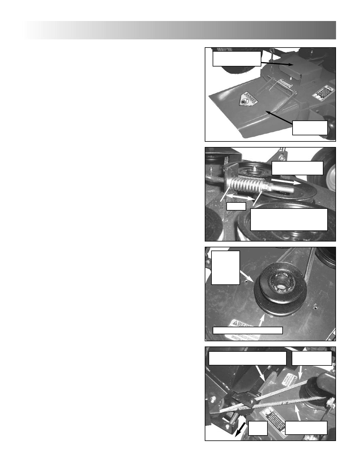
STEP 1: Remove pin, rod and spring securing dis-
charge deflector to mower deck, and remove
deflector. Store deflector for future use. IMPOR-
TANT: Never operate any mower without a dis-
charge deflector or grass catcher securely in
place.
STEP 2: Remove two bolts securing right deck pul-
ley guard to mower deck and remove guard. Set
bolts aside for future assembly step. Store guard
for future use. IMPORTANT: Never operate any
mower without a pulley guard securely in place.
STEP 3: Loosen both nuts all the way to end of
rod. NOTE: Deck belt tension rod is located under
foor rest of machine. Removing foot rest will aid in
accessing rod.
STEP 4: Remove belt from right deck pulley.
Remove nut securing pulley to blade spindle, and
remove pulley, replacing with supplied replace-
ment pulley. Replace nut, and torque to 70-80 ft-
lbs. NOTE: Nut secures blade bolt in place.
Support bolt from beneath while replacing pulley.
IMPORTANT: Use gloves when working under
deck. Sharp blades can cause injury.
Replace deck belt onto bottom groove of pulley.
With deck in lowest cutting position, retighten nuts
on deck tension rod until spring length measures
2-5/16”.
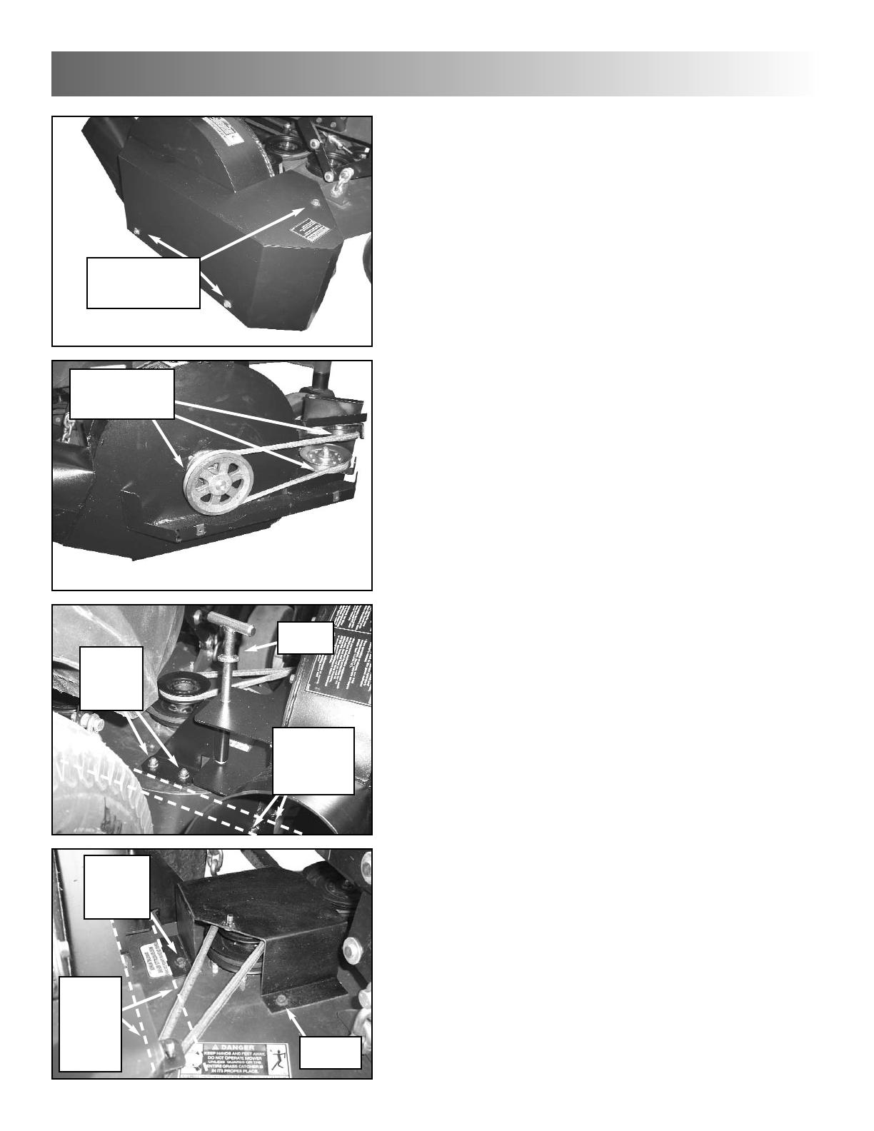
STEP 5: Set blower against deck discharge. Align
holes in blower mount with holes in deck discharge
tabs, and secure with rod and pin removed in Step
1. NOTE: Do not include deflector spring in rod
installation.
STEP 6: Pull back on idler tension release handle,
and install blower belt around top groove of deck
pulley. NOTE: Make sure belt is not rolled or
twisted when installing.
5
REMOVE PULLEY
GUARD
REMOVE
DEFLECTOR
LOOSEN NUTS TO
END OF ROD
REPLACEMENT PULLEY
INSTALL BLOWER AND
SECURE WITH ROD AND PIN
FROM UPPER
IDLER PULLEY
TO LOWER
IDLER PULLEY
PULL
BACK
BLOWER KIT INSTALLATION
REPLACE
BELT
ONTO
BOTTOM
GROOVE
WHEN RETIGHTENING NUTS,
ADJUST UNTIL SPRING
LENGTH MEASURES 2-5/16”
2-5/16”
3
unit assembly
6
STEP 7: Slip tube of locking pin bracket into blow-
er mount, and secure with T-handle pin, making
sure pin goes through both upper and lower part of
blower mount. Then align base of pin bracket par-
allel with rear of deck, and, using bracket as a tem-
plate, drill two 7/16” holes through deck. Insert two
3/8-16 x 1” bolts up through deck and bracket,
securing with hex flange nuts. Tighten securely.
IMPORTANT: Use gloves when working under
deck. Sharp blades can cause injury.
STEP 8: Lay supplied pulley guard onto deck.
Align hole in front flange with front mounting hole
in deck, and secure with one of the two bolts
securing original guard. Do not tighten yet.
Align side flange of guard with side of deck, and,
using other hole in guard as a template, drill one
9/32” hole in deck and install other bolt. (NOTE:
Bolt is self-tapping.) Tighten both bolts securely.
STEP 6a: Remove bolts securing impeller pulley
cover to blower, and remove cover.
STEP 6b: Check to see that blower belt is routed
around impeller pulley and idler pulleys after belt is
installed onto deck pulley. Then replace cover.
Tighten bolts securely. IMPORTANT: Never oper-
ate any mower without a pulley guard securely in
place.
REMOVE BOLTS,
THEN REMOVE
COVER
CHECK TO SEE
THAT BELT IS
ON PULLEYS
INSERT
PIN
DRILL
HOLES &
INSTALL
BOLTS
ALIGN
BRACKET
WITH REAR
OF DECK
DRILL
HOLE &
INSTALL
BOLT
INSTALL
BOLT
ALIGN
SIDE OF
GUARD
WITH
SIDE OF
DECK

STEP 9: Install belt guard between pulley guard
and belt guard support clip on front part of blower
mount. Secure with two 5/16 nylon wing nuts.
Tighten nuts securely.
!! Warning: Weight kit must be installed prior to
installing bagger unit. Failure to do so may
result in longitudal tipping of unit.
STEP 10: Insert the four narrow weight bars
through opening in side of foot rest. Be sure holes
in weights are all aligned. Next, insert the two 1/2-
13 x 5 bolts through the five wide weight bars, and
lay the wide bars against front of footrest, inserting
bolts through holes in narrow bars. Secure with
1/2” split lock washers and nuts. Tighten securely.
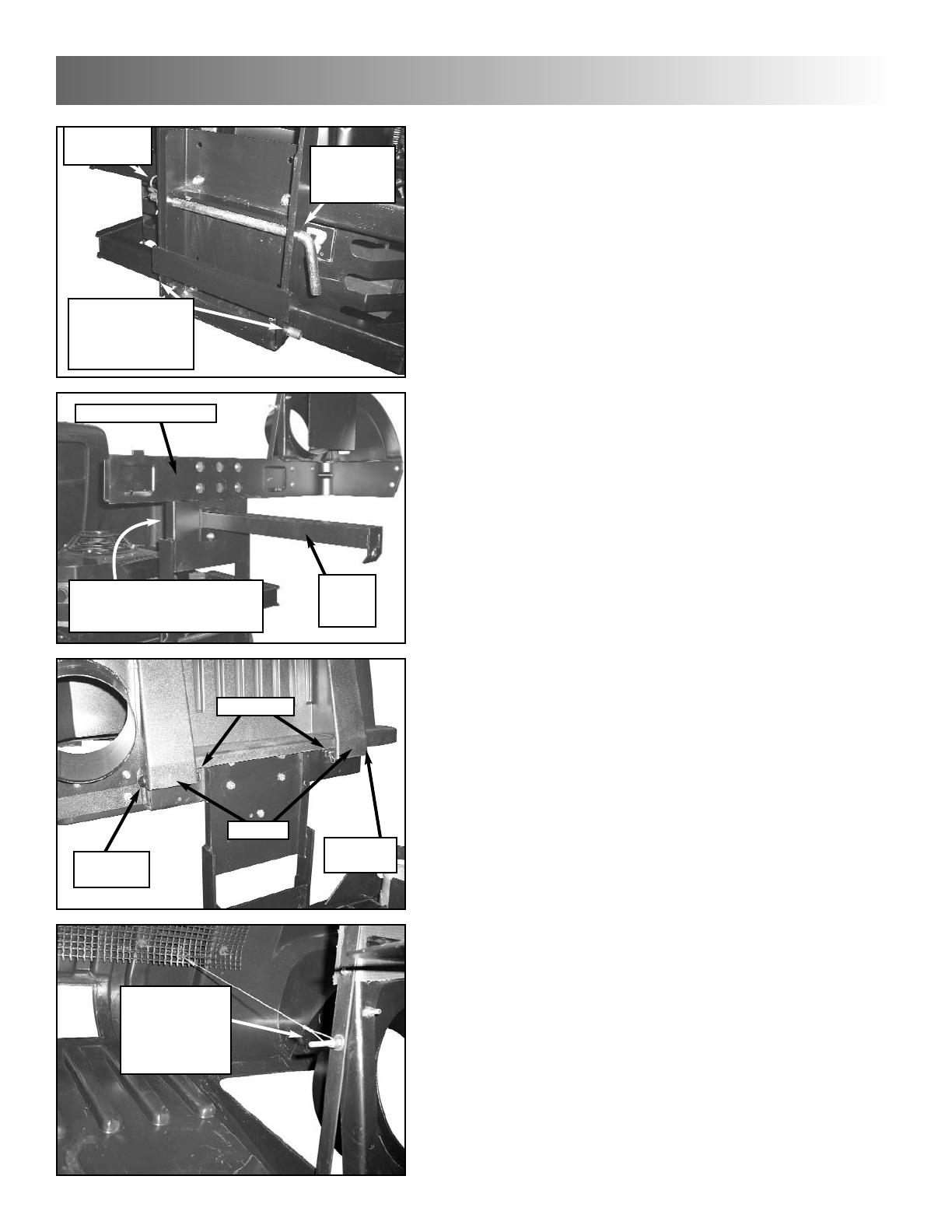
STEP 11: Install bumper mount standoffs onto rear
bumper of machine, utilizing existing hardware on
machine. NOTE: Invert hardware when installing
standoffs, installing bolts out through bumper with
nuts facing out.
NOTE: When installing standoffs, be sure that the
bumper mount plate mounting holes along the
back bar of the standoffs are located towards the
right side of the machine. Refer to the Parts List
section of the manual.
STEP 12: Install bumper mount plate onto stand-
offs with four 5/16-18 x 3/4 hex cap screws, secur-
ing with four 5/16-18 flange lock nuts. Tighten
securely.
Also, install muffler deflector (see inset) onto muf-
fler, making sure deflector directs exhaust off to the
side of the mower. Fasten with clamp.
IMPORTANT: FAILURE TO INSTALL MUFFLER
DEFLECTOR MAY RESULT IN A FIRE.
unit assembly
3
7
INSTALL BELT GUARD
AND SECURE WITH
WING NUTS
WEIGHT KIT INSTALLATION
4 NARROW BARS
THROUGH
FOOTREST
5 WIDE BARS
AGAINST
FOOTREST
BAGGER KIT INSTALLATION
USE EXISTING
HARDWARE
HOLES TOWARD RIGHT
STEP 16: Lay cover assembly on cross assembly.
Align hinges on cross assembly with hinges on
cover, and install one round head pin through each
set of hinge holes, securing with a hair pin.
STEP 17: Slip looped end of cover support cord
onto threaded stud on hose adapter assembly.
Secure end of cord with one 3/16” flat washer and
10-32 nyloc nut (not shown). Run nut all the way in
on thread, but leave cord loose enough to swivel.
3
unit assembly
STEP 13: Hook bottom of bagger frame onto pins
in bottom of bumper mount plate. Then slide lock-
ing rod through aligned holes in bagger frame and
bumper mount plate, securing with bridge pin.
STEP 14: Install cross assembly onto bagger
frame with four 3/8-16 x 3/4 bolts and hex flange
lock nuts, tightening securely. Insert bolts back
through bagger frame and into cross assembly.
STEP 15: Insert two 5/16-18 x 3/4 bolts through
reinforcement plate (not shown; refer to Parts List
- Catcher Mount Group), then through holes in
bagger frame. Install cover latch arm onto bolts
and secure with hex flange lock nuts, tightening
securely. NOTE: Use the leftmost set of holes in
the bagger frame when installing arm.
8
HOOK BAGGER
FRAME ONTO
BUMPER MOUNT
PLATE PINS
SLIDE ROD
THROUGH
HOLES
INSERT PIN
INTO ROD
CROSS ASSEMBLY
COVER
LATCH
ARM
HINGES
ROUND
HEAD PIN
HAIR PINS
ROUND
HEAD PIN
SLIP CORD
ONTO STUD
AND SECURE
WITH WASHER
& NUT
INSTALL REINFORCEMENT
PLATE ON BACK SIDE OF
BAGGER FRAME
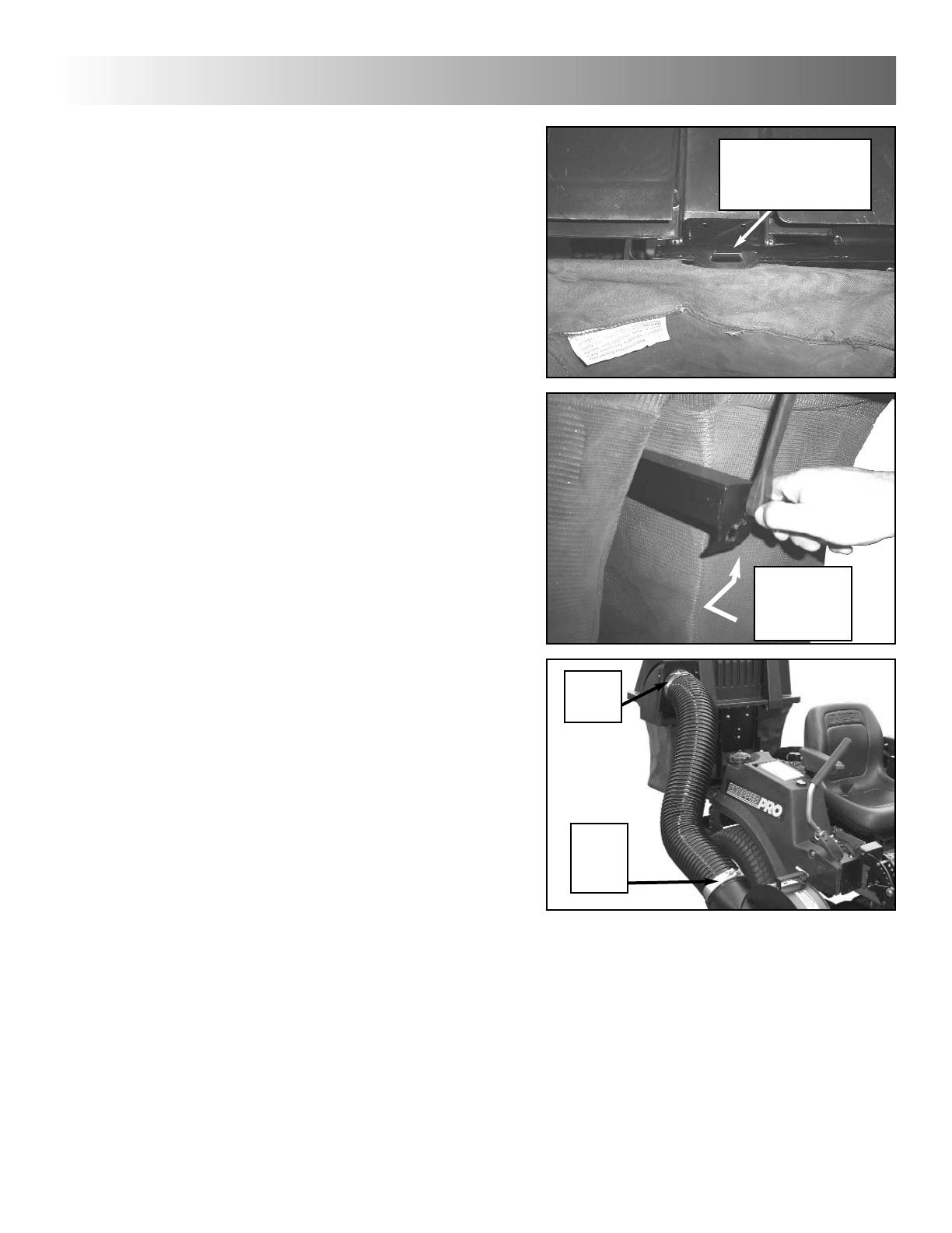
STEP 18: Install bags onto cross assembly by
hooking slot in bag hanger onto tabs in channel
assembly.
STEP 19: Close cover and lock in place by hook-
ing lock knob into slot in cover latch arm.
STEP 20: Slip one hose clamp onto each end of
hose (use the clamp with the black quick-release
knob at the blower end), and install hose between
blower and bagger. Make sure to fit hoses firmly
onto adapters. Tighten clamps securely.
unit assembly
3
9
SLIP SLOT IN GRASS
BAG HANGER ONTO
TAB ON CROSS
ASSEMBLY
INSERT,
THEN MOVE
OVER AND
UP TO LOCK
CLAMP
WITH
NUT
CLAMP
WITH
BLACK
KNOB

4
unit operation & maintenance
10
INTRODUCTION
Follow operation and maintenance instructions in the
Operator’s Manual provided with the Snapper CZT/HZT.
GRASS CATCHER OPERATION
1. Select desired cutting height. Choose a setting that will
not attempt to cut off too much at once, overloading the
machine.
2. After starting engine and allowing a brief warm up peri-
od, move engine speed control to highest setting.
3. Drive machine to cutting area. Engage blades.
4. Select a slow forward ground speed until familiar with
conditions. Do not select a speed that is too fast, caus-
ing the machine to become overloaded.
5. The weight of the grass catcher and contents will affect
the stability and handling of the machine. Avoid sudden
starts and sharp turns. Reduce speed on slopes, and
DO NOT operate machine on slopes exceeding 10
degrees (18% grade). Operate machine up and down
slopes. DO NOT operate machine across the face of
slopes. Turn blades off when traveling up slope.
6. Empty grass catcher bags often to minimize effect on
stability and handling. Over filling the catcher bags will
reduce performance and cause clogging of the hose,
blower and deck.
7. Do not operate the machine with the Grass Catcher
cover open. The entire Grass Catcher must be installed,
the cover closed and latched properly before operating.
EMPTYING GRASS CATCHER
1. Empty Grass Catcher bags often to avoid overfilling.
Overfilling reduces performance and causes clogging of
hose, blower and deck.
2. Turn blades off. Drive machine to location the clippings
are to be dumped. DO NOT operate blades in reverse.
If you must back machine to dump clippings in desired
location, LOOK and SEE behind and down for children,
pets and hazards before and while backing.
3. Stop motion of machine by returning Motion Control(s)
to Neutral (N). Set Park Brake. Stop engine.
4. Unlatch cover and lift. Remove bags and dump debris
in desired location.
5. After dumping, to maintain peak performance, check
the catcher screen located on the inside of the Cover
Assembly to make sure it is clean and free of any build
up. Clean as required with brush or broom.
6. Close catcher cover and latch.
7. Re-start engine and drive machine to cutting area. Set
engine speed to highest setting, engage blades and
resume operation.
IF THE GRASS CATCHER BECOMES CLOGGED
The grass catcher may become plugged if the conditions
are too severe, the catcher is overfilled, or the machine is
used improperly. If plugging does occur, attempt the follow-
ing:
1. Engine speed too slow – set engine speed control to
“FAST” position.
2. Empty catcher bags more often.
3. Clean screen on cover assembly.
4. Ground speed too fast – cut at slower speed.
5. Removing too much grass – raise cutting height, cut
partial width, and cut lawn more frequently.
6. Grass is too wet from rain or dew – allow grass to dry.
7. Blades are dull or worn – inspect blades and replace as
necessary. Use only genuine SNAPPER replacement
blades.
8. Deck, blower, or hose has clipping build up – clean all
clippings from all internal surfaces.
(Continued On Next Page)
WARNING
DO NOT attempt to remove any clogs from deck, blow-
er, or hose with engine or blade running. STOP engine.
STOP blades. Set brake. Remove key. Make sure
blades and all rotating components have come to a
complete stop before removing any catcher or unclog-
ging any catcher component.
! !
WARNING
DO NOT put fingers or hands inside blower! STOP
blades. STOP engine. Remove key. Use only a stick, or
other suitable means, to clear the blower of clogs or
other obstructions!
WARNING
DO NOT attempt any adjustments, maintenance or
repairs with engine running. STOP blades. STOP
engine. Remove key.
WARNING
Grass Catcher components are subject to deteriora-
tion. Inspect frequently. Replace worn or damaged
components immediately. Use only genuine SNAPPER
replacement parts.
! !
! !
! !

unit operation & maintenance
4
11
IF THE GRASS CATCHER BECOMES CLOGGED
(Continued From Previous Page)
To Clear A Plugged Hose
1. Stop blades. Stop engine. Remove key.
2. After all rotating components (engine, blower, blades)
have come to a complete stop, loosen hose clamp at
outlet of blower, and remove hose from blower.
3. Clear any obstructions from hose. If necessary, use a
stick to reach into the hose.
4. Reinstall hose to blower and securely tighten hose
clamp.
To Clear A Plugged Blower
1. Stop blades and blower. Stop engine. Remove key.
2. After all rotating components have come to a complete
stop, loosen the hose clamp at the outlet of the blower.
3. Remove hose from blower.
4. Using a stick or similar object, clear all obstructions
from blower. DO NOT INSERT HAND.
5. Reinstall hose to blower and securely tighten hose
clamp.
GRASS CATCHER MAINTENANCE
Grass Catcher components are subject to wear and deteri-
oration during normal usage. Inspect all components fre-
quently for signs of wear and deterioration. Replace worn or
damaged components immediately.
BEFORE EACH USE
1. Perform pre-start checklist and maintenance as
instructed in the SNAPPER CZT/HZT Operator’s
Manual and Engine Owner’s Manual included with the
machine.
2. Catcher. Inspect all catcher components. Replace all
worn or damaged parts.
3. Catcher Bags. Check bags often for wear or damage.
Replace worn or damaged bags immediately, using only
SNAPPER approved replacement bags.
4. Deck, Blower, Hose. Clean grass build up from deck,
blower, hose, covers and rear cover screen. To maintain
peak performance make sure screen is clean at each
dumping.
5. Hose. Check hose for wear, tears and holes. Replace
as needed.
6. Blades. Check blades for sharpness, wear, flatness
and damage. Refer to CZT/HZT Operator’s Manual for
blade wear limits and sharpening/replacement instruc-
tions.
7. Blower. Check blower impeller, blower housing and
inlet/outlets for signs of wear and deterioration. Replace
as needed. Check all fasteners and hardware to insure
none are missing and all are tightened securely.
Lubricate impeller shaft bearings with 1 to 3 shots of
General Purpose grease from a grease gun.
8. Belts. Check belts for wear and fraying. Replace as
needed.
9. Idler Arm. Check idler arm to insure it pivots freely and
bushings are not worn. Replace worn bushings as
needed.
WARNING
Grass Catcher bags used on SNAPPER products are made of woven fab-
ric, and are subject to deterioration and wear during normal usage. Check
condition of bags before each use. Immediately replace worn or damaged
catcher bags with only bags recommended by SNAPPER. The Grass
Catcher is optional equipment on some models.

5
unit breakdown & parts list
12

SSnnaappppeerr ZZ--VVaacc BBlloowweerr UUnniitt GGrroouupp -- CCZZTT // HHZZTT MMooddeellss
Item Part No. Qty Description
1 3046782 1 WELDMENT, Blower Belt Guard
2 91121 1 NUT, 1/2-13 Hex Nyloc
3 90183 1 WASHER, 1/2" Flat SAE
4 3021097 1 PULLEY, A Groove Idler, Steel
5 44995 1 IDLER STUD (3/8-24 thread)
6 91804 2 FLAT WASHER, 9/16 Type Narrow
7 14409 2 FLANGE BEARING, 9/16" I.D. (powdered metal)
8 10776 1 RETAINING RING, 1/2"
9 3046824 1 BELT RETAINER, Idler
10 91527 1 SCREW, 5/16-18 x 1-1/4" Hex Head Cap, GR5
11 3047253 1 WELDMENT, Idler Arm
12 91601 1 NUT, 5/16-18 Hex Flange Lock
13 91218 1 SCREW, 1/2-13 x 2-1/2" Hex Head Cap, GR5
14 3046781 1 WELDMENT, Blower Housing
15 3046853 1 BACK PLATE, Blower
16 91541 7 SCREW, 5/16-18 x 3/4" Hex Washer Self-Tap
17 3022832 2 BEARING, Pillow Block, Blower (includes grease fitting)
18 90839 8 NUT, 7/16-14 Hex Center Lock, GR5 or B
19 3031920 4 SCREW, 7/16-14 x 1-1/2" Hex Head Cap, GR5
20 3046854 1 IMPELLER, Fast Vac Blower (weldment)
21 3031919 4 SCREW, 7/16-14 x 1-1/4" Hex Head Cap, GR5
22 90613 2 NUT, 3/8-16 Hex Flange Lock
23 3046813 2 BELT RETAINER
24 3043613 2 PULLEY, Flat Idler, 2-3/4" O.D.
25 90122 9 WASHER, 3/8" Flat SAE
26 91560 1 SCREW, 3/8-16 x 2-1/4" Hex Head Cap, GR5
27 91518 1 NUT, 3/8-24 Hex Nyloc
28 91305 1 SCREW, 3/8-16 x 2" Hex Head Cap, GR5
29 92111 3 U-CLIP, 5/16-18
30 91541 3 SCREW, 5/16-18 x 3/4" Hex Washer Self-Tap
unit breakdown & parts list
5
13

5
unit breakdown & parts list
14

SSnnaappppeerr ZZ--VVaacc BBlloowweerr MMoouunntt GGrroouupp -- CCZZTT // HHZZTT MMooddeellss
Item Part No. Qty Description
1 3036323 1 BELT, A Section, 91.125" effective length
2 3037161 1 WELDMENT, Belt Cover, Deck
3 ----- -- NOT USED
4 91537 2 WING LOCKNUT 5/16-18
5 3037162 1 BELT GUARD
6 3046806 1 PULLEY, Blower Input
7 78298 1 PULLEY, Spindle
8 3027505 1 WELDMENT, Blower Mount
9 3027507 1 WELDMENT, Guard Support Bracket
10 91541 4 SCREW, 5/16-18 x 3/4" Hex Washer Self-Tap
11 3027508 1 WELDMENT, Deck Mount Bracket
12 91304 2 SCREW, 3/8-16 x 1" Hex Head Cap, GR5
13 90613 4 NUT, 3/8-16 Hex Flange Lock
14 3032118 1 WELDMENT, T-Handle Pin
15 91527 1 SCREW, 5/16-18 x 1-1/4" Hex Head Cap, GR5
16 91601 1 NUT, 5/16-18 Hex Flange Lock
17 90951 2 NUT, 5/16-18 Hex Large Flange Center Lock
18 3020807 1 SPRING, Idler, Fast Vac
19 12315 1 KEY, 1/4 Square x 1.44
20 91617 1 SCREW, 3/8-16 x 6" Hex Head Cap, GR5
unit breakdown & parts list
5
15
5
unit breakdown & parts list
16

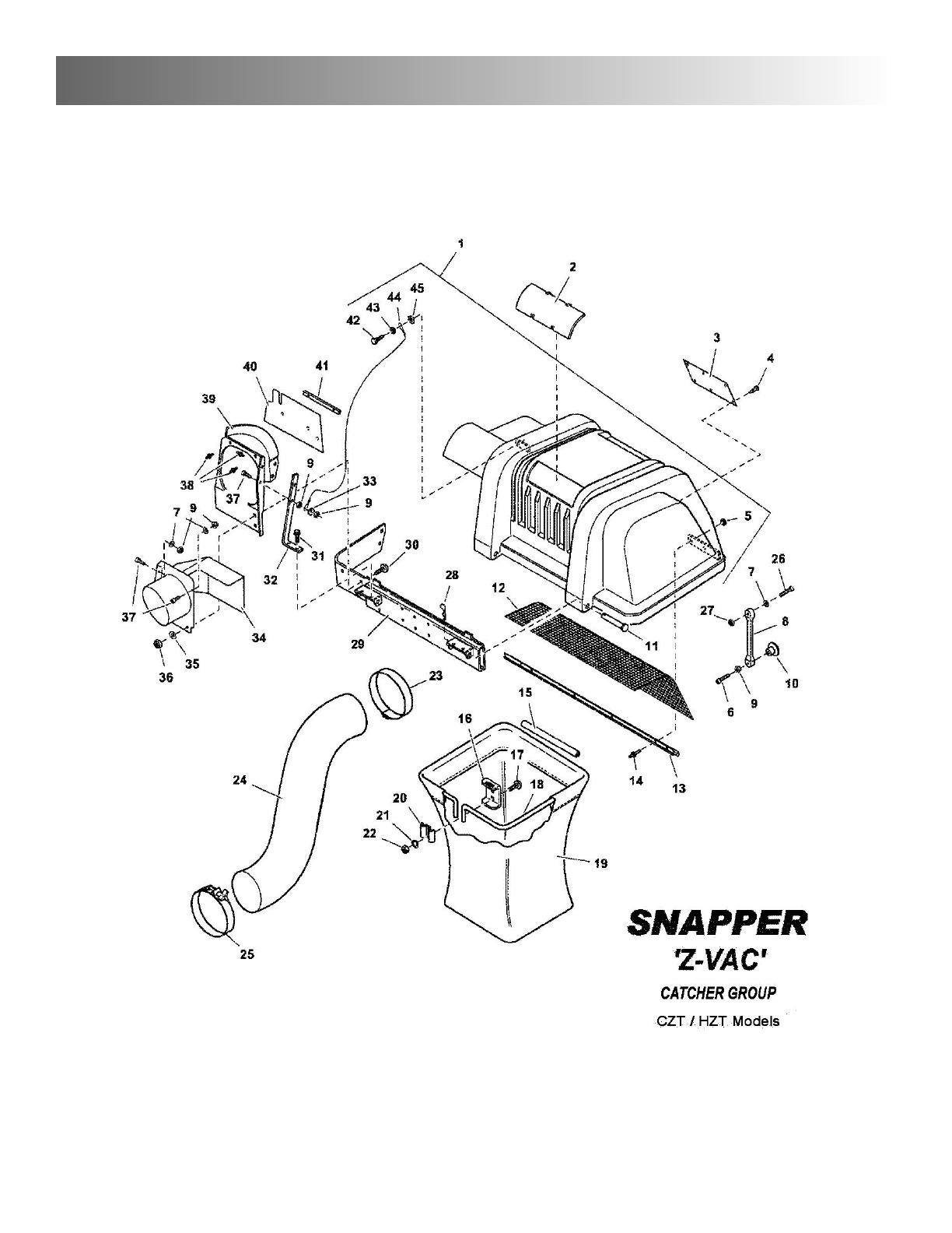
SSnnaappppeerr ZZ--VVaacc CCaattcchheerr GGrroouupp -- CCZZTT // HHZZTT MMooddeellss
Item Part No. Qty. Description
1 3046861 1 ASSEMBLY, 2 Bag Cover and Screen
(includes Item No. 1a, 5, 12, 13, 14, 42, 43, 44, 45)
1a 1704033 1 CATCHER TOP, 2 Bag
2 1704180 2 WINDOW, Cover
3 1704405 1 DECAL, Safety, Grass Bag
4 1667248 6 CLIP, Canoe
5 1910531 4 WASHER, .188 Rivet
6 90922 1 SCREW, #10-32 x 1-1/2 Hex Washer Head Machine w/Nylon Patch
7 91702 3 WASHER, .19 x .38 x .06 Flat
8 3021670 1 STRAP, Rubber
9 90376 5 NUT, #10-32 Hex Nyloc
10 3022838 1 KNOB
11 0960367 2 PIN, Round Head
12 1703700 1 SCREEN
13 1704057 1 SEAL, Clip
14 91578 4 POP RIVET, 3/16 x .265 Alum.
15 1675707 2 TUBE CLIP, Grass Bag
16 1703807 2 HANGER, Grass Bag
17 90316 4 BOLT, 5/16-18 x 3/4" Square Neck Carriage, GR5
18 1703855 2 HOOP, Grass Bag
19 3000847 2 GRASS BAG
20 1672023 2 CLAMP, Grass Bag
21 90187 4 WASHER, 5/16" Split Lock
22 91511 4 NUT, 5/16-18 Hex, GR5 or B
23 3022875 1 HOSE CLAMP, Upper
24 3022833 1 HOSE, Snapper Fast Vac
25 3022876 1 HOSE CLAMP, Lower, Fast Vac
26 91757 1 SCREW, #10-24 x 1-1/4" Hex Head Cap, GR5
27 91290 1 NUT, #10-24 Hex Nyloc
28 15067 2 HAIR PIN, 1.6
29 1703822 1 CROSS ASSEMBLY
30 91530 5 BOLT, 1/4-20 x 3/4" Carriage
31 91084 2 SCREW, 1/4-20 x 3/8" Hex Washer Self-Tap
32 1704507 1 STRAP, Tube Support
33 91702 1 WASHER, .191 I.D. Flat
34 3046722 1 WELDMENT, Hose Adapter/Deflector
35 90598 3 WASHER, 1/4" Flat
36 91603 5 NUT, 1/4-20 Hex Nyloc
37 90883 3 SCREW, 10F x 7/8" Pan Head Cross Recess
38 91241 3 POP RIVET, 3/16”
39 1704075 1 SUPPORT, Tube
40 3046774 1 SEAL, 2 Bag Catcher
41 1704508 1 BRACKET, Seal
42 1960400 1 SCREW, #10-12 x 5/8” Hex Washer Self-Tap
43 90052 1 WASHER, 1/4” Split Lock
44 1705876 1 CABLE, Double Loop
45 1933886 1 NUT, Speed
unit breakdown & parts list
5
17
5
unit breakdown & parts list
18

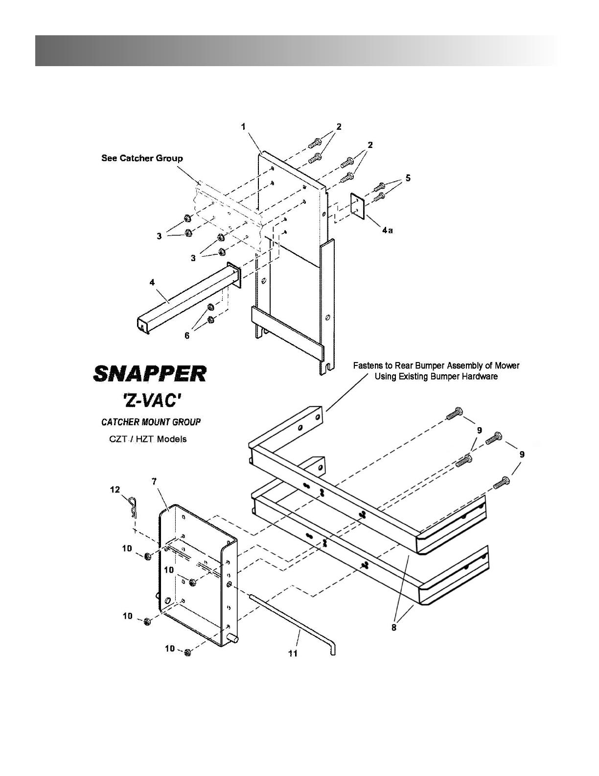
SSnnaappppeerr ZZ--VVaacc CCaattcchheerr MMoouunntt GGrroouupp -- CCZZTT // HHZZTT MMooddeellss
Item Part No. Qty. Description
1 3046687 1 WELDMENT, Bagger Mount Frame
2 91086 4 SCREW, 3/8-16 x 3/4" Hex Head Cap, GR5
3 91619 4 NUT, 3/8-16 Hex Flange Lock
4 3046831 1 ARM, Cover Latch
4a 3046829 1 REINFORCEMENT PLATE
5 91318 2 SCREW, 5/16-18 x 3/4" Hex Head Cap, GR5
6 91601 2 NUT, 5/16-18 Hex Flange Lock
7 3046995 1 WELDMENT, Bumper Mounting Plate
8 50551 2 STANDOFF, Bumper Mount
9 91318 4 SCREW, 5/16-18 x 3/4" Hex Head Cap
10 91601 4 NUT, 5/16-18 Hex Flange Lock
11 3046693 1 ROD, Support
12 15067 1 HAIRPIN, Clip
-- 3039122 1 EXHAUST DEFLECTOR (Not Shown)
-- 3039123 1 MUFFLER CLAMP (Not Shown)
unit breakdown & parts list
5
19

5
unit breakdown & parts list
20
/