Page is loading ...

OPER ATOR'S MANUAL
ROTARY MOWER
29900
Rev. 3/14/2008
Tested. Proven. Unbeatable.
42C-6

2 Introduction
Gen’l (Rev. 2/19/2008)
TO THE DEALER:
Assembly and proper installation of this product is the responsibility of the Woods
®
dealer. Read manual instructions
and safety rules. Make sure all items on the Dealer’s Pre-Delivery and Delivery Check Lists in the Operator’s Manual
are completed before releasing equipment to the owner.
The dealer must complete the Product Registration online at the Woods Dealer Website or complete the mail-in
form included with the Operator’s Manual. If using the mail-in form, the dealer is to return the prepaid postage portion to
Woods, give one copy to the customer, and retain one copy. Failure to register the product does not diminish
customer’s warranty rights.
TO THE OWNER:
Read this manual before operating your Woods equipment. The information presented will prepare you to do a better and
safer job. Keep this manual handy for ready reference. Require all operators to read this manual carefully and become
acquainted with all adjustment and operating procedures before attempting to operate. Replacement manuals can be
obtained from your dealer. To locate your nearest dealer, check the Dealer Locator at www.WoodsEquipment.com, or in
the United States and Canada call 1-800-319-6637.
The equipment you have purchased has been carefully engineered and manufactured to provide dependable and
satisfactory use. Like all mechanical products, it will require cleaning and upkeep. Lubricate the unit as specified.
Observe all safety information in this manual and safety decals on the equipment.
For service, your authorized Woods dealer has trained mechanics, genuine Woods service parts, and the necessary
tools and equipment to handle all your needs.
Use only genuine Woods service parts. Substitute parts will void the warranty and may not meet standards required for
safe and satisfactory operation. Record the model number and serial number of your equipment in the spaces
provided:
Model: _______________________________ Date of Purchase: _____________________
Serial Number: (see Safety Decal section for location) ____________________________________
Provide this information to your dealer to obtain correct repair parts.
Throughout this manual, the term NOTICE is used to indicate that failure to observe can cause damage to equipment.
The terms CAUTION, WARNING, and DANGER are used in conjunction with the Safety-Alert Symbol (a triangle with
an exclamation mark) to indicate the degree of hazard for items of personal safety.

Introduction 3
29900 (Rev. 7/6/2007)
TABLE OF CONTENTS
INTRODUCTION . . . . . . . . . . . . . . . . . . . . . . . . . . . . . . . . . . . . . . . . . . . . . . 2
GENERAL INFORMATION . . . . . . . . . . . . . . . . . . . . . . . . . . . . . . . . . . . . . . 3
SAFETY RULES . . . . . . . . . . . . . . . . . . . . . . . . . . . . . . . . . . . . . . . . . . . . . . 4
SAFETY DECALS . . . . . . . . . . . . . . . . . . . . . . . . . . . . . . . . . . . . . . . . . . . . . 6
OPERATION . . . . . . . . . . . . . . . . . . . . . . . . . . . . . . . . . . . . . . . . . . . . . . . . . 7
SERVICE . . . . . . . . . . . . . . . . . . . . . . . . . . . . . . . . . . . . . . . . . . . . . . . . . . . . 8
ASSEMBLY . . . . . . . . . . . . . . . . . . . . . . . . . . . . . . . . . . . . . . . . . . . . . . . . . . 9
DEALER CHECK LISTS . . . . . . . . . . . . . . . . . . . . . . . . . . . . . . . . . . . . . . . 15
PARTS LISTS . . . . . . . . . . . . . . . . . . . . . . . . . . . . . . . . . . . . . . . . . . . . . . . 16
BOLT TORQUE CHART . . . . . . . . . . . . . . . . . . . . . . . . . . . . . . . . . . . . . . . 25
BOLT SIZE CHART . . . . . . . . . . . . . . . . . . . . . . . . . . . . . . . . . . . . . . . . . . . 26
PRODUCT WARRANTY . . . . . . . . . . . . . . . . . . . . . . . INSIDE BACK COVER
REPLACEMENT PARTS WARRANTY . . . . . . . . . . . . . . . . . . . BACK COVER
GENERAL INFORMATION
The purpose of this manual is to assist you in operating
and maintaining your mower. Read it carefully. It fur-
nishes information and instructions that will help you
achieve years of dependable performance. These
instructions have been compiled from extensive field
experience and engineering data. Some information
may be general in nature due to unknown and varying
operating conditions. However, through experience
and these instructions, you should be able to develop
procedures suitable to your particular situation.
The illustrations and data used in this manual were cur-
rent at the time of printing but, due to possible inline
production changes, your mower may vary slightly in
detail. We reserve the right to redesign and change the
cutters as may be necessary without notification.
Throughout this manual, references are made to right
and left directions. These are determined by standing
behind the mower facing the direction of forward travel.
Si no lee Ingles, pida ayuda a
alguien que si lo lea para que le
traduzca las medidas de seguridad.
LEA EL INSTRUCTIVO!
!
This Operator’s Manual should be regarded as part of the machine.
Suppliers of both new and second-hand machines must make sure
that this manual is provided with the machine.
(Rev. 3/14/2008)

4 Safety
42C Safety Rules (Rev. 7/9/2007)
TRAINING
Safety instructions are important! Read all
attachment and power unit manuals; follow all
safety rules and safety decal information. (Replace-
ment manuals and safety decals are available from
your dealer. To locate your nearest dealer, check
the Dealer Locator at www.WoodsEquipment.com,
or in the United States and Canada call 1-800-319-
6637.) Failure to follow instructions or safety rules
can result in serious injury or death.
If you do not understand any part of this manual
and need assistance, see your dealer.
Know your controls and how to stop engine and
attachment quickly in an emergency.
Operators must be instructed in and be capable
of the safe operation of the equipment, its attach-
ments, and all controls. Do not allow anyone to
operate this equipment without proper instructions.
Never allow children or untrained persons to
operate equipment.
PREPARATION
Check that all hardware is properly installed.
Always tighten to torque chart specifications
unless instructed otherwise in this manual.
Always wear relatively tight and belted clothing
to avoid getting caught in moving parts. Wear
sturdy, rough-soled work shoes and protective
equipment for eyes, hair, hands, hearing, and head;
and respirator or filter mask where appropriate.
Make sure attachment is properly secured,
adjusted, and in good operating condition.
Remove accumulated debris from this equip-
ment, power unit, and engine to avoid fire hazard.
Make sure all safety decals are installed.
Replace if damaged. (See Safety Decals section for
location.)
Make sure shields and guards are properly
installed and in good condition. Replace if damaged.
Inspect and clear area of stones, branches, or
other hard objects that might be thrown, causing
injury or damage.
OPERATION
You may not be able to stop the tractor safely if
the clutch or brake pedal mechanisms are improp-
erly adjusted, allowing them to contact mower
components.
When the mower lift stops are installed as
instructed in this manual, properly adjusted clutch
and brake pedal mechanisms will not contact
mower components. You should frequently check
that the tractor clutch and brake pedal mechanisms
are in adjustment.
If the clutch or brake pedal mechanisms can
contact mower components, do not put mower into
service until properly adjusted.
Do not put mower into service unless discharge
chute is installed and in good condition. Replace if
damaged.
Keep bystanders away from equipment.
Do not operate or transport equipment while
under the influence of alcohol or drugs.
Never direct discharge toward people, animals,
or property.
Operate only in daylight or good artificial light.
Keep hands, feet, hair, and clothing away from
equipment while engine is running. Stay clear of all
moving parts.
Always comply with all state and local lighting
and marking requirements.
Never allow riders on power unit or attachment.
Always sit in power unit seat when operating
controls or starting engine. Place transmission in
neutral, engage brake, and ensure all other con-
trols are disengaged before starting power unit
engine.
Look down and to the rear and make sure area
is clear before operating in reverse.
Do not operate or transport on steep slopes.
Safety is a primary concern in the design and
manufacture of our products. Unfortunately, our
efforts to provide safe equipment can be wiped
out by an operator’s single careless act.
In addition to the design and configuration of
equipment, hazard control and accident preven-
tion are dependent upon the awareness, con-
cern, judgement, and proper training of
personnel involved in the operation, transport,
maintenance, and storage of equipment.
It has been said, “The best safety device is an
informed, careful operator.” We ask you to be
that kind of operator.
SAFETY RULES
ATTENTION! BECOME ALERT! YOUR SAFETY IS INVOLVED!

Safety 5
42C Safety Rules (Rev. 7/9/2007)
Do not stop, start, or change directions sud-
denly on slopes.
Use extreme care and reduce ground speed on
slopes and rough terrain.
Watch for hidden hazards on the terrain during
operation.
Stop power unit and equipment immediately
upon striking an obstruction. Turn off engine,
remove key, inspect, and repair any damage before
resuming operation.
TRANSPORTATION
Always comply with all state and local lighting
and marking requirements.
Never allow riders on power unit or attachment.
Do not operate PTO during transport.
Watch for hidden hazards on the terrain.
Do not operate or transport on steep slopes.
Do not operate auxiliary hydraulics during
transport.
Do not operate or transport equipment while
under the influence of alcohol or drugs.
MAINTENANCE
Before dismounting power unit or performing
any service or maintenance, follow these steps:
disengage power to equipment, lower the 3-point
hitch and all raised components to the ground,
operate valve levers to release any hydraulic pres-
sure, set parking brake, stop engine, remove key,
and unfasten seat belt.
Do not modify or alter or permit anyone else to
modify or alter the equipment or any of its compo-
nents in any way.
Always wear relatively tight and belted clothing
to avoid getting caught in moving parts. Wear
sturdy, rough-soled work shoes and protective
equipment for eyes, hair, hands, hearing, and head;
and respirator or filter mask where appropriate.
Never go underneath equipment (lowered to the
ground or raised) unless it is properly blocked and
secured. Never place any part of the body under-
neath equipment or between moveable parts even
when the engine has been turned off. Hydraulic
system leak down, hydraulic system failures,
mechanical failures, or movement of control levers
can cause equipment to drop or rotate unexpect-
edly and cause severe injury or death. Follow Oper-
ator's Manual instructions for working underneath
and blocking requirements or have work done by a
qualified dealer.
Make sure attachment is properly secured,
adjusted, and in good operating condition.
Keep all persons away from operator control
area while performing adjustments, service, or
maintenance.
Make certain all movement of equipment com-
ponents has stopped before approaching for ser-
vice.
Frequently check blades. They should be sharp,
free of nicks and cracks, and securely fastened.
Do not handle blades with bare hands. Careless
or improper handling may result in serious injury.
Your dealer can supply genuine replacement
blades. Substitute blades may not meet original
equipment specifications and may be dangerous.
Tighten all bolts, nuts, and screws to torque
chart specifications. Check that all cotter pins are
installed securely to ensure equipment is in a safe
condition before putting unit into service.
Make sure all safety decals are installed.
Replace if damaged. (See Safety Decals section for
location.)
Make sure shields and guards are properly
installed and in good condition. Replace if damaged.
Wear gloves when installing belt. Be careful to
prevent fingers from being caught between belt
and pulley.
STORAGE
Block equipment securely for storage.
Keep children and bystanders away from stor-
age area.
SAFETY RULES
ATTENTION! BECOME ALERT! YOUR SAFETY IS INVOLVED!

6 Safety
29900 (Rev. 7/6/2007)
4 - SERIAL NUMBER PLATE
1 - 25505
ROTATING BLADES AND
THROWN OBJECTS
Do not put hands or feet under or into mower when
engine is running.
Before mowing, clear area of objects that may be
thrown by blade.
Keep bystanders away.
Keep discharge chute and guards in place and in good
condition.
BLADE CONTACT OR THROWN OBJECTS CAN
CAUSE SERIOUS INJURY OR DEATH.
DANGER
53425-B
2 - 53425
BE CAREFUL!
Use a clean, damp cloth to clean safety decals.
Avoid spraying too close to decals when using a
pressure washer; high-pressure water can enter
through very small scratches or under edges of
decals causing them to peel or come off.
Replacement safety decals can be ordered free
from your Woods dealer. To locate your nearest
dealer, check the Dealer Locator at
www.WoodsEquipment.com, or in the United States
and Canada call 1-800-319-6637.
MODEL NO. SERIAL NO.
Woods Equipment Company
Oregon, Illinois, U.S.A.
DB2202B
SAFETY & INSTRUCTIONAL DECALS
ATTENTION! BECOME ALERT! YOUR SAFETY IS INVOLVED!
Replace Immediately If Damaged!

Operation 7
29900 (Rev. 7/6/2007)
OPERATION
■ Do not allow children or unqualified persons to
operate equipment.
■ Keep bystanders away from equipment while it
is in operation.
■ Stop mower and tractor immediately upon
striking an obstruction. Turn off engine, remove
key, inspect and repair any damage before resum-
ing operation.
■ Alway wear relatively tight and belted clothing
to avoid entanglement in moving parts. Wear
sturdy, rough-soled work shoes and protective
equipment for eyes, hands, hearing and head.
TRACTOR OPERATING INSTRUCTION
Operate tractor at full governed RPM. If forward speed
is too high, a lower tractor gear can be used.
ATTITUDE ADJUSTMENT
Attitude can be adjusted by selecting the proper hole
when connecting the channel arms to the mounting
frame.
NOTICE
■ The mower should be carried on tractor lift
mechanism at all times; SKIDS should only lift
mower when it encounters bumps or unevenness.
However, skids should be adjusted so they are car-
ried close to the ground.
MOWING GRASS
When mowing grass, adjust machine so that it is level.
CUTTING WEEDS
When shredding high weeds, it may be desirable to
make two trips over the area - the first one with the
machine adjusted in a higher position.
SHREDDING STALKS
When shredding stalks adjust attitude of machine so
that front end is high.
AWARNING
ACAUTION

8 Service
29900 (Rev. 7/6/2007)
SERVICE
LUBRICATION
Grease blade spindle shaft every 24 hours of operation
until some grease is forced out around top of shaft.
This is necessary to ensure that enough grease has
been forced in to reach top bearing of spindle. V-belt
idlers have sealed ball bearings and do not need lubri-
cation.
V-BELT
Belt should be adjusted so it is tight enough to hold
power of tractor when mowing. When belt replacement
is necessary, use only the belt recommended by your
Woods dealer. These belts are of special construction
for shock loading and severe use. Idler pulleys must be
kept in proper alignment so that V-belt will run
smoothly.
MAIN SPINDLE ASSEMBLY
The spindle assembly is equipped with two tapered
roller bearings. Proper adjustment is maintained by a
sleeve welded on the shaft. These bearings are not
intended to be adjusted during their useful life.
BLADE SERVICING
Removal
Loosen locking bolt, rotate blade retainer and drive
blade pin up out of crossbar and blade. Slide blade out
of crossbar. Always sharpen or replace blades in pairs
to maintain proper balance. Use genuine Woods
blades for replacement. They are made of special steel
alloy and are subjected to rigid heat-treat and inspec-
tion requirements. Substitute blades may not meet
these rigid specifications and could be dangerous.
Installation
Figure 1. Clockwise Rotation Crossbar
NOTE: On 42-6 mowers, all crossbars rotate in a clock-
wise rotation except models L42AC/B & C-6 C L42A-6.
Ensure you order correct replacement blades and
install them correctly for your machine. Insert blade into
crossbar; ensure cutting edge points in direction of
crossbar rotation. Install blade pin into crossbar
through blade; rotate blade retainer over blade and
tighten locking bolt.
LUBRICATION OF OVERRUNNING
CLUTCH
Oil only occasionally and just enough to keep a film of
oil on internal parts. Excess oil will prevent ratchet
teeth from fully engaging, resulting in premature failure.
CLEANING
After Each Use
● Remove large debris such as clumps of dirt, grass,
crop residue, etc. from machine.
● Inspect machine and replace worn or damaged
parts.
● Replace any safety decals that are missing or not
readable.
Periodically or Before Extended Storage
● Clean large debris such as clumps of dirt, grass,
crop residue, etc. from machine.
● Remove the remainder using a low-pressure water
spray.
1. Be careful when spraying near scratched or torn
safety decals or near edges of decals as water
spray can peel decal off surface.
2. Be careful when spraying near chipped or
scratched paint as water spray can lift paint.
3. If a pressure washer is used, follow the advice
of the pressure washer manufacturer.
● Inspect machine and replace worn or damaged
parts.
● Sand down scratches and the edges of areas of
missing paint and coat with Woods spray paint of
matching color (purchase from your Woods
dealer).
● Replace any safety decals that are missing or not
readable (supplied free by your Woods dealer).
See Safety Decals section for location drawing.
LA1
(Rev. 3/14/2008)

Assembly 9
29900 (Rev. 7/6/2007)
ASSEMBLY
■ Keep all persons away from operator control
area while performing adjustments, service or
maintenance.
■ Always wear relatively tight and belted clothing
to avoid entanglement in moving parts. Wear
sturdy, rough-soled work shoes and protective
equipment for eyes, hands, hearing and head.
SPINDLE INSTALLATION
Insert spindle assembly (11) up through bottom of
mower frame (1). Be sure to index grease zerk toward
mower front for ease of lubrication. Secure spindle to
frame with four 1/2 x 1-3/4" bolts (26), 1/2" lock wash-
ers (27) and nuts (28). Torque to 85 lbs-ft.
Figure 2. Spindle Installation
BLADE INSTALLATION
Remove bolt (12) and apply an anti-seize lubricant to
threads and reinstall.
Rotate blade retainer washer (10) off of blade pin (11)
and remove blade pin.
Install blades (14) with cutting edge toward closed side
of crossbar. Check that the words “this side down” are
on the bottom side of the blade when installed. Insert
blade pin (11) through blades, rotate blade pin retainer
washer (10) over pin, tighten bolt (12) snugly. Do not
over tighten; do not follow torque chart recommenda-
tions.
Figure 3. Blade Installation
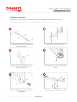
FRONT CORNER BAFFLE INSTALLATION
Attach front corner baffle (2) to right front corner of
mower frame with 3/8 x 3/4" carriage bolt (20) and lock
nuts (25).
Figure 4. Front Corner Baffle Installation
SIDE SKID INSTALLATION
With cutting height set, adjust side skids to within 1/2"
of ground. Never operate mower with weight on side
skids. Properly adjusted side skids are designed to
carry mower over uneven ground and minimize scalp-
ing.
Attach side skids (10) to mower frame with 3/8 x 1"
bolts (21), lock washers (23) and nuts (24).
AWARNING
ACAUTION
LA3
LA5

10 Assembly
29900 (Rev. 7/6/2007)
Figure 5. Side Skid and Side Shield
SIDE SHIELD OR DISCHARGE CHUTE
INSTALLATION
A side shield and discharge chute are provided for right
side of mower. The side shield should be used for nor-
mal operating conditions. The discharge chute may be
used to replace side shield for very heavy mowing con-
ditions.
■ Do not operate mower unless either discharge
chute or side shield is installed.
■ Keep hands and feet away from mower while
tractor engine is running. Stay clear of all moving
parts.
Left Side Shield Installation
Attach side shield (9) to mower with 3/8 x 1" bolts (21)
and 3/8" flanged lock nuts (24). Insert bolts from inside
out. See Figure 5.
Right Side Shield and Baffle Installation
Attach rear of side shield baffle (5) to mower, and front
portion to right side shield (4) with 3/8 x 3/4" carriage
bolts (20) and lock nuts (25), inserted from inside out.
Figure 6. Side Shield & Baffle Installation
Discharge Chute Installation
Remove side shield (4). Attach discharge chute (13) to
mower frame with 3/8 x 1" bolts (20) and 3/8" flanged
lock nuts (25).
Figure 7. Discharge Chute Installation
OVER-RUNNING CLUTCH INSTALLATION
See page 20. Install the two keys (13) in spindle shaft
and place over-running clutch pulley unit on spindle
shaft with bolted flange on top. Make sure it lines up
with keys in shaft. Place three washers on top of spin-
dle shaft (16), install weather cap (15), and secure with
3/8 x 1-1/2" bolt (14) and lock washer (4).
CLUTCH BELT SHIELD INSTALLATION
See page 16. Install drive belt on pulley, then install
drive shield (6) to mower frame with 3/8 x 1" bolts (21),
3/8" lock washers (23) and nuts (24).
NOTICE
■ This shield is not used when mower is installed
on IH Low Boy tractors because of minimum clear-
ance under tractor.
LA6
ADANGER
ACAUTION
LA8

Assembly 11
29900 (Rev. 7/6/2007)
MOUNTING FRAME ASSEMBLY
Push Channel / Push Channel Mounting
Angles and Lift Bars
Loosely assemble the following (see page 18):
Attach right push channel mounting angle (53) to right
rear deck rail and rear mower deck with 1/2" x 1-1/2"
carriage bolts (83) and flange lock nuts (91). Attach left
push channel mounting angle (57) to left rear deck and
rear of mower in same manner.
Insert 1/2" x 1-3/4" bolts (85) through hole in deck rails
immediately behind belt shield. Install slotted hole in
push channel arm (54) on bolt. Install lift arm (40) on
bolt and fasten with lock washer (88) and nut (89).
Attach push channel arm (54) to channel arm mounting
angle (53) with 1/2" x 1-1/2" carriage bolts (83) and
flange lock nuts (91). Mounting angles (53 & 57) have
an upper and lower slot for a cutting height of 1" to 2".
Use lower slot when a higher cutting height is desired.
NOTE: Earlier models do not have lower slots. Should
you need to raise cutting height, drill a 9/16" diameter
hole 3/4" below the upper slot.
Should belt stretch or pulley wear cause the belt to
become too long, re-tension by moving mower forward
and using front hole in push channel arms as an
attachment point.
Leave push channel arms loosely assembled until
mower is mounted to tractor.
Belt Guide
Clamp belt guide (55) to left channel arm using clamp
plate (56) and 3/8" x 2-1/2" hex head cap screws (78),
lock washers (79) and nuts (80). After belt has been
installed, adjust guide fore and aft in the channel so the
belt runs about through the center of the guide.
Idler Bracket
Adjust tractor drawbar to center hole of its adjustment
and slide idler bracket (46) into place. Clamp idler
bracket to tractor drawbar plates with two clamp plates
(45) and four 1/2" x 2" bolts (86), lock washers (88) and
nuts (89). If for some reason, the tractor drawbar
mounting plates have been removed from the tractor,
they must be reinstalled in order to clamp the idler
bracket to them.
Idlers to Idler Bracket
Install 5/8" x 3-1/2" carriage bolt (94) in through the
right side of the vertical slots on idler bracket (46).
Place three 5/8" flat washers (9) over carriage bolt on
left side of slots. Install idlers (47) over bolt and secure
with 5/8" flat washer (95), lock washer (96) and nut
(97).
Mower Frame to Idler Bracket
Slide mower frame under tractor. Adjust front axle out
to provide clearance of mower when turning. See Fig-
ure 10. Attach push channel arms (54) to idler bracket
(46) with 5/8" x 1-1/2" clevis pins (92) and secure with
safety pins (75). Tighten all push channel arm and
mounting bracket hardware installed in
Push Channel /
Push Channel Mounting Angles and Lift Bars.
Drive Pulley
Remove paint from hub of drive sheave (48). Install
bushing (49) and slide assembly onto tractor PTO
shaft, set in from end of shaft approximately 1/2".
Loosen both idlers, place belt over drive sheave (48)
and two idlers (47). Press idlers down to tighten belt.
Then tighten nuts, keeping both idlers in about the
same relative position. Sight down over drive sheave
and align drive sheave with idlers by moving it in or out
of the PTO shaft. Then alternately tighten bushing bolts
evenly to 12 lbs-ft torque, alternating back and forth at
least six times. On IH Cub, adjust belt tension with
mower raised to 4" cutting height.
Lift Arms
Attach upper lift arm (42) to hydraulic lift arm on right
side of tractor with two 5/8 x 1-3/4" bolts (93), lock
washers (96) and nuts (97). Offset of arm (42) should
be toward the outside of tractor. Assemble center lift
arm (43) to upper lift arm (42) using 5/8 x 1-3/4" bolt
(93), 5/8 x 1 x 7/16" sleeve (44), flat washer (95) and
deformed thread nut (97).
Assemble lower lift arm (41) to center lift arm (43) with
1/2 x 1-1/2" bolt (84) and deformed thread nut (90). Do
not tighten this bolt too tight as arms (41 & 42) need to
pivot freely on this bolt.
Attach lower end of lift arm (41) to lift bars (40) using
1/2 x 2" clevis pin (87) and 3/16 x 1" cotter pin (76).
Adjust stops on lift control lever so mower does not hit
bottom of tractor or tractor tires when fully raised. For
tractors not equipped with hydraulics see page 22 for
manual lift.
V-Belt Shield
Bolt V-belt shield attachment plate (50) to tractor plow
bracket holes with two 1/2 x 1" bolts (82) and lock
washers (88). Attach V-belt shield (51) to attachment
plate (50) with 3/8" wing nut (81).

12 Assembly
29900 (Rev. 7/6/2007)
Figure 8. Mounting Frame Assembly Photo

Assembly 13
29900 (Rev. 7/6/2007)
Figure 9. Mounting Frame Assembly Photo with Rear Shield

14 Assembly
29900 (Rev. 7/6/2007)
Figure 10. Lift Assembly Photo

Dealer Check List 15
29900 (Rev. 3/14/2008)
DEALER CHECK LISTS
PRE-DELIVERY CHECK LIST
(DEALER’S RESPONSIBILITY)
Inspect the equipment thoroughly after assembly to
ensure it is set up properly before delivering it to the
customer.
The following check lists are a reminder of points to
inspect. Check off each item as it is found satisfactory
or after proper adjustment is made.
___ Check that all safety decals are installed and in
good condition. Replace if damaged.
___ Check that shields and guards are properly
installed and in good condition. Replace if dam-
aged.
___ Properly attach implement to tractor and make all
necessary adjustments.
___ Check all bolts to be sure they are tight.
___ Check and grease all lubrication points as identi-
fied in “Service”.
___ Check that blades have been properly installed.
DELIVERY CHECK
(DEALER’S RESPONSIBILITY)
___ Instruct customer how to lubricate and explain
importance of lubrication.
___ Point out the safety decals. Explain their meaning
and the need to keep them in place and in good
condition. Emphasize the increased safety haz-
ards when instructions are not followed.
___ Present Operator's Manual and request that cus-
tomer and all operators read it before operating
equipment. Point out the manual safety rules,
explain their meanings and emphasize the
increased safety hazards that exist when safety
rules are not followed.
___ Show customer the safe, proper procedures to be
used when mounting, dismounting, and storing
equipment.
___ Point out all guards and shields. Explain their
importance and the safety hazards that exist
when not kept in place and in good condition.

16 Parts
29900 (Rev. 7/6/2007)
42-6 CW MAIN FRAME ASSEMBLY

Parts 17
29900 (Rev. 7/6/2007)
42-6 CW MAIN FRAME ASSEMBLY
REF PART QTY DESCRIPTION
1 9874 1 Frame
2 26403 1 Front corner baffle
3 4141 1 Right side skid
4 26396 1 Right side shield
5 26402 1 Side shield baffle
6 27663 1 Blade spindle belt shield
7 ----- 1 Overrunning clutch (see page 20)
8 3444 1 Access hole cover
9 26397 1 Left side shield
10 4142 1 Left side skid
11 ----- 1 CW Blade spindle (see page 24)
12 3975KT 1 CW Blade kit
13 31878 1 Side discharge chute
HARDWARE
20 24597 * 3/8 NC x 3/4 Carriage bolt
21 839 * 3/8 NC x 1 HHCS GR5
22 976 * 3/8 NC x 1-1/2 HHCS GR5
23 838 * 3/8 Lock washer
24 835 * 3/8 NC Hex nut, plated
25 14350 3/8 NC Flanged lock nut
26 24576 * 1/2 NC x 1-3/4 HHCS GR5
27 855 * 1/2 Lock washer ZP
28 1093 * 1/2 NC Hex nut, plated
29 1287 * 3/8 NC Wing nut
* Standard hardware, obtain locally
REF PART QTY DESCRIPTION

18 Parts
29900 (Rev. 7/6/2007)
42C-6 MOUNTING FRAME ASSEMBLY DRAWING

Parts 19
29900 (Rev. 7/6/2007)
42C-6 MOUNTING FRAME ASSEMBLY
REF PART QTY DESCRIPTION
40 27657 2 Lift bar
41 1533 1 Bottom lift arm
42 1441 1 Upper lift arm
43 1500 1 Center lift arm
44 484 1 5/8 x 1 x 7/16 Heat-treated sleeve
45 1513 2 Idler bracket clamp plate
46 1491 1 Idler pipe
47 4072 2 7-5/16 OD Idler sheave
48 1505 1 1 BK 7.4H Drive sheave
49 1506 1 .978, 10 Spline H bushing with bolts
50 1489 1 V-Belt shield attachment plate
51 1473 1 V-Belt shield
52 27652 1 V-Belt special (W117)
53 27658 1 Right channel mounting angle
54 27660 2 Push channel assembly
55 2296 1 Belt guide frame
56 2292 1 Belt guide clamp plate
57 27659 1 Left channel mounting angle
58 4788 1 Complete decal set
59 ----- 1 Manual lift (see page 22)
60 52310 1 French safety decal set
HARDWARE
75 2688 * 5/32 Hair cotter pin
76 1256 * 3/16 x 1 Cotter pin
77 2457 * 1/4 NC x 3/4 HHCS GR5
78 2290 * 3/8 NC x 2-1/2 HHCS GR5
79 838 * 3/8 Lock washer ZP
80 835 * 3/8 NC Hex nut, plated
81 1287 * 3/8 NC Wing nut
82 25475 * 1/2 NC x 1 HHCS GR5 full thread
83 29893 * 1/2 NC x 1-1/2 Carriage bolt, GR5
84 3379 * 1/2 NC x 1-1/2 HHCS GR5
85 24576 * 1/2 NC x 1-3/4 HHCS GR5
86 3699 * 1/2 NC x 2 HHCS GR5
87 409 1/2 x 2 Clevis pin
88 855 * 1/2 Lock washer ZP
89 1093 * 1/2 NC Hex nut, plated
90 765 * 1/2 NC Lock nut ZP
91 11900 * 1/2 NC Flanged hex lock nut
92 4097 5/8 x 1-1/2 Clevis pin
93 4548 * 5/8 NC x 1-3/4 HHCS, HT
94 5655 * 5/8 NC x 3-1/2 Carriage bolt, HT
95 692 * 5/8 Flat washer
96 1286 * 5/8 Heavy lock washer
97 230 * 5/8 NC Hex nut, plated
* Standard hardware, obtain locally
REF PART QTY DESCRIPTION

20 Parts
29900 (Rev. 7/6/2007)
OVERRUNNING CLUTCHES
IMPORTANT NOTE: After installing clutch, rotate it back-
wards to see that it ratchets freely. If it does not, add
another washer (16) under cap (15) & rotate clutch again.
REF PART QTY DESCRIPTION
1 ------ * 1 1/8 Pipe plug (used on earlier
models)
2 3174 2 Oil seal
3 839 * 4 3/8 NC x 1 HHCS GR5
4 838 * 5 3/8 Lock washer ZP
5 3333 1 Ratchet cap (includes 2 & 6 installed)
6 3175 2 1-3/4 x 2-1/4 x 1/2 Bushing
7 3171 1 Ratchet with hex hole
8 3176 1 Compression spring
9 3177 1 Drive hex
10 3178 1 1-3/4 x 3-3/8 x 18 GA Shim
11 6935 1 .070 x 3-1/2 x 5 Gasket
12 3332 1 Special 9.4 sheave (includes 2 & 6
installed)
13 3912 2 Key, 1/4 x 3/8 x 2
14 12169 * 1 3/8 NC x 1-1/4 HHCS GR5
15 3172 1 Weather cap
16 1536 3 1-1/4 x 1-3/4 Shim -or-
16 565 * 4 3/8 Flat washer
* Standard hardware, obtain locally
/