Harbor Freight Tools 90402 is a hydraulic door closer designed for small and medium doors with a maximum capacity of 132 lbs. It features adjustable closing and latching speeds, allowing you to customize the door's operation to your specific needs. The closer is easy to install and comes with all necessary mounting hardware. With its durable construction and reliable performance, the Harbor Freight Tools 90402 is an excellent choice for both residential and commercial applications.
Harbor Freight Tools 90402 is a hydraulic door closer designed for small and medium doors with a maximum capacity of 132 lbs. It features adjustable closing and latching speeds, allowing you to customize the door's operation to your specific needs. The closer is easy to install and comes with all necessary mounting hardware. With its durable construction and reliable performance, the Harbor Freight Tools 90402 is an excellent choice for both residential and commercial applications.


-
 1
1
-
 2
2
-
 3
3
-
 4
4
-
 5
5


Harbor Freight Tools 90402 is a hydraulic door closer designed for small and medium doors with a maximum capacity of 132 lbs. It features adjustable closing and latching speeds, allowing you to customize the door's operation to your specific needs. The closer is easy to install and comes with all necessary mounting hardware. With its durable construction and reliable performance, the Harbor Freight Tools 90402 is an excellent choice for both residential and commercial applications.
Ask a question and I''ll find the answer in the document
Finding information in a document is now easier with AI
Related papers
-
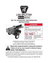 Greyhound 65761 User manual
-
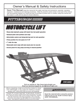 Pittsburgh Motorcycle 1000 lb. Capacity Motorcycle Lift Owner's manual
-
Harbor Freight Tools 91039 User manual
-
-
-
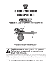 Greyhound 94837 User manual
-
-
-
-
Central Hydraulics 93033 User manual


Other documents
-
Drill Master 95527 Assembly And Operation Instructions
-
Assa Abloy King 640 Installation guide
-
Sentinel 5000 Series Installation guide
-
 ShelterLogic 90402 Operating instructions
-
LCN 4640CS Installation Instructions Manual
-
-
Hager 5200 Series Installation Instructions Manual
-
Hagerco 5200 Series - Grade 1 Heavy Duty - Door Closer Installation guide
-
-
