Page is loading ...

kinq
ASSAABLOY'
i
* II *•
BODY
SIZE
4
installation
MODEL:
640,
eso,
740,750,840,
sso
Instructions
1640.
teso.
1740.1750.
mo.
tsso
A
Type
Regular
Arm
Installation
I£
Right
hand
door
SPEED
ADJUSTING
VALVE
PULL
side
of
door
Bjype
Top
Jamb
Installation
Left
hand
door
SPEED
ADJUSTING
VALVE
PULL
side
of
door
Please
note
This
drawing
is not to
full
scale. Therefore,
do not use it as
your
template
to
locate
the
hole
positions
while
you
fabricate
your
door
and
frame
for the
installation
of
this
product.
Instead,
make
the
measurements
needed
manually
without
the use of the
enclosed
template which
is not to
full
scale.
REGULAR
ARM
(PULL
SIDE)
Mounting
i
i
1
(25)
3/4
(IS)
i
!
4
1
.61/2.
.13/4]
1
rM
f
— fe
P
(101)
1
Right
ham
Lett
hand
"
(ItS)
'_:(44.4
ISLJEJ
>
9
1/16
""
(230)
1
door
shown,
door
opposite.
}
(
i,
CM-4)
V
t/
•
v
Dimension*:
Inchaa
(mm)
Hinge
or
Pivot
U
B
INSTALLATION
INSTRUCTIONS
1.
Using
template dimensions shown above, mark
FORE(4)
HOLES
ON
DOOR
for
door closer
and
TWO(2)
HOLES
ON
FRAME
for arm
shoe.
2.
Drill
pilot
holes
in
door
and
frame
for
#14
all-purpose
screws
or
drill
and tap for
1/4-20
machine
screws.
3.
Install adjustable
forearm/arm
shoe
to
frame
using
screws
provided.
4.
Mount closer
on
door using
screws
provided. SPEED ADJUSTING
VALVE
MUST
BE
POSITIONED TOWARD HINGE EDGE.
5.
Install
main
arm
to
too
pinion
shaft,
perpendteular
to
door
as
shown
below. Secure
tightly
with
arm
screw/washer assembly provided.
6.
Adjust
length
of
forearm
so
that
forearm
is
perpendicular
to
frame
when assembled
to
preloaded
main
armOllustration
below).
Secure
forearm
to
main
arm
with
screw/washer
assembly provided.
7.
Adjust
closing
speed
of
door,
8.
Snap
pinion
cap
over shaft
at
bottom
of
closer.
Blype
TOP
JAMB
(PUSH
SIDE)
Mounting
"
(101)
i
i
i
4-
1
^
r
^
3/4
1/2
4
,
y
(230)
>
61/4
?
1
f
(K|
i
j
112.7)
(15M
<««•«)
Left hand door shown.
Right
hand door
opposite.
Dimensions:
Inches
(mm)
r
'1
3/4
(44.4)
Hinge
or
Pivot
INSTALLATION
INSTRUCTIONS
1.
Using
template dimensions shown above, mark
FORE(4)
HOLES
ON
FRAME
for
door closer
and
TWO(2) HOLES
ON
DOOR
for arm
shoe.
2.
Drill
pilot
holes
in
door
and
frame
for
#14
all-purpose
screws
or
drill
and tap for
1/4-20
machine screws.
3.
Install
adjustable forearm/arm shoe
to
door
using
screws
provided.
4.
Mount closer
on
frame
using
screws
provided. SPEED ADJUSTING
VALVE
MUST
BE
POSITIONED
TOWARD
HINGE
EDGE.
5.
Install
main
arm to top
pinion
shaft, perpendicular
to
door
as
shown
below. Secure
tightly
with
arm
screw/washer assembly provided.
6.
Adjust
length
of
forearm
so
that forearm
is
perpendicular
to
door
when assembled
to
preloaded main
arm
(Illustration
below).
Secure
forearm
to
main
arm
with
screw/washer
assembly provided.
7.
Adjust
closing
speed
of
door,
Snap
pinion
cap
over shaft
at
bottom
of
closer.

king
ASSAABLOY
4
BODY
SIZE
Installation
MODEL:
040,
eso,
740,750,840,
sso
Instructions
1640.
ieso.
1740.1750.1840.
isso
Cryp^
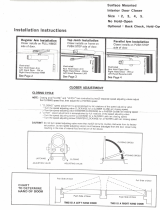
Parallel
Arm
Installation
o
/
/\
-•'/
*
__b
SMfcizf1
x~x_
L\*
Tw
Main
/V&J~7
ViP*5^
\m
\JWT__)
SPEED
ADJUSTING
Left
hand
door
^
1]
=^»
°r
\E
PULL
side
of
door
W
Type
Opposite
<-,
Riflht
hand
door
||
*~i
<^S
^^^^^
PULL
SPFFD
side
of
door
orCCU
X\
\"v
x^Si7r
/
*!-=aV
ADJUSTING
n
,,i
J
^C_
y-Yy^S
Main
(
r^a|
)
arm
VALVE
Please
note
This
drawing
is not to
full
scale.
Therefore,
do not use it as
your
template
to
locate
the
hole
positions
while
you
fabricate
your
door
and
frame
for the
installation
of
this product. Instead,
make
the
measurements
needed manually without
the use of the
enclosed
template which
is not to
full scale.
Clype
PARALLEL
ARM
(PUSH
SIDE)
Mounting
8
3/10
(211)
3/4
L_J
j
i
IS/IS
aa-s)
a/4
33
(121)
(230)
Left
hand door shown.
Right
hand
door
opposite.
Dimensions: Inches (mm)
Hinge
or
Pivot
INSTALLATION
INSTRUCTIONS
1.
Using
template
dimensions
shown above, mark
FORE(4)
HOLES
ON
DOOR
for
door closer
and
THREE
(3)
HOLES
ON
FRAME
for
parallel
bracket.
2.
Drill
pilot
holes
in
door
and
frame
for
#14
all-purpose
screws
or
drill
and tap for
1/4-20
machine screws.
3.
Install
Parallel
Arm
Bracket shoe
to
frame
using
screws
provided.
4.
Mount closer
on
door
using
screws provided. SPEED
ADJUSTING
VALVE
MUST
BE
POSITIONED
TOWARD
AWAY
FROM
HINGE
EDGE.
5.
Install
main
arm to top
pinion
shaft, with
arm
pointing
toward speed
adjusting
screw.
Secure
fighBy
with
arm
screw/washer
assembly
provided.
6.
Remove
arm
shoe from fore
arm and
discard.
Install
ROD end of
fore
arm
to
bracket
using
screw/washer
assembly provided.
Adjust
length
of
fore
arm to set arm
elbow approximately
1
-1/2"(38mm)
from
door(refer
to
Illustration
below).
Attach fore
arm to
main
arm by
rotating main
arm
away
from
door. Secure forearm
to
main
arm
using
screw/washer
assembly provided.
7.
Adjust
length
of
fore
arm
so
when
it
is
attached
to
main
arm
the
main
arm
wiH
be
slightly
away
from
parallel
with
closed
door
and
assemble
at
elbow then tighten
tocknut.
8.
Adjust
door
closing
speed
by
speed
adjusting
valves.
9.
Snap
pinion
cap
over shaft
at
bottom
of
closer.
CLOSER
ADJUSTMENT
CLOSING
SPEED
ADJUSTMENT
-
Turn
the
speed adjusting valve
CLOCKWISE
for
SLOWER
CLOSE
arc
closing speed,
-
Turn
the
speed
adjusting
valve COUNTER-CLOCKWISE
for a
FASTER
CLOSE
arc
closing
speed.
BACK
CHECK
CONTROL
(OPENING
CYCLE)
- To
increase back check intensity, turn back check control valve clockwise.
- To
decrease back check intensity, turn back check control valve
counter-clockwise.
-
Never close this valve
completely.
CAUTION!
I
Do not
turn speed
adjusting
valve more than
two(2)
full
turns
counter-
clockwise from factory
set
position,
as two
speed
adjusting
valves
could
become
dislodged
from
the
door closer
body,
resulting
in the
loss
of
internal
fluid
and
failure
of the
device.
SWEEP
Adjusting
Valve
\H
Adjusting
Valve
\K
or
DELAY
Adjusting
Valvel
Closing
cycle
Opening
cycle
/
