Page is loading ...

Eclipse
E-Zip Side Retention Screen
Installation Instructions
Version 10.3.16
Please carefully read all of the instructions BEFORE installation. If you have
any questions, please contact our Technical Service Department at
800-501-3850 from 8am to 5pm ET, or 845-645.6995 after hours.

Whether you are an experienced installer or this is your first installation, please read these instruc-
tions carefully before attempting the installation.
Before you start, take a minute to ensure your installation will proceed as smoothly as possible.
- Open the box and lay out all of the components
- Measure the screen and make sure it will fit in the desired space
- Make sure you have all the tools needed
- You will need at least two people, depending on the size and location to set the unit in place
PLEASE NOTE: FASTENERS ARE NOT INCLUDED
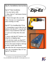
IMPORTANT NOTE
TRACK ATTACHMENT:
up to 5’ drop: 2 mounting points per track
over 5’ drop: 3 mounting points per track
IMPORTANT: DO NOT LEVEL DOWN EACH TRACK SEPARATELY. THE DISTANCE BETWEEN
BOTH TRACKS NEED TO BE THE SAME. IMPROPER INSTALLATION WILL NOT LET THE
SCREEN OPERATE PROPERLY.
6”
6”
fig 1
fig 4
fig 3
fig 2
fig 5
fig 7
fig 6
fig 8
Level
&
Plumb
Top
Bottom
2
Figures for instructions

3
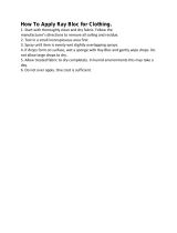
Eclipse E-Zip Pivot End Packing Note
PLEASE READ THIS BEFORE PROCEEDING
Thanks to our newly designed pivot end assembly, the roller tube is installed properly in the cassette
box housing. Nothing special needs to be done before proceeding to the installation of the unit.
To Remove The Roller Tube Assembly IF Needed:
Step #2
Once the front panel is removed, squeeze the white plastic Retaining End Clip that is locked into
the Pivot End Lock. (fig 2).
Step #1
With the unit installed, remove the two screws securing the front panel - one on each end (fig 1).
Step #3
You can now lower the Roller Tube assembly. Please note the motor cord will need to be fed into
the Cassette Box or End Cover for additional movement.
fig 1
fig 2
Pivot End Clip Reinstallation:
Please note that the collar on the white plastic Retaining End Clip is placed between the
End Cover and the Pivot End Lock
Collar is placed between End
Cover and Pivot End Lock
Pivot
End Lock
Retaining
End Clip
Properly installed - collar is
hidden & fully engaged
Remove this
screw and
the one on
the other end
Squeeze this clip
with your fingers
or with pliers

Tools Needed
Optional Tools
4

Eclipse E-Zip Track & Hem Bar Options & Details
For Recessed/Inside Track Mounting:
Once the track is mounted, twist
in the track PVC inserts as shown
2.0”
1.3”
0.8”
1.9”
Side Track Details (top view)
Hem Bar Details
(side view)
screw cover
fabric
track PVC insert
brush/seal location
3/8”, 3/4”, 11/2” options
Drill here on the guide line in the extrusion
Drill through both layers
For Wall/Surface Track Mounting:
Drill here on the guide line in the extrusion
Drill through both layers
All Mounting:
Once the unit is fully installed and
functioning properly, install the
track front cover
5

Surface Mount Installation Procedures:
Mounting The Box Version
Step# 1
Remove all the foam packing and set it aside. Then remove the plastic wrap being very careful not to
cut the fabric or damage the finish on the hardware.
Step #2
Lay the cassette box housing on the ground with the side cover leg down and remove the two screws
holding the front cassette box cover (fig 1). Put the screws in a safe place as you will need to reinstall
them later. Now lift off the front cover and place it out of direct sunlight - the metal gets really hot in
the sun!
Step #3
Remove the roller tube assembly from the cassette housing - with needle nose pilars, remove the
metal motor retaining ring (fig 2), then squeeze the white plastic pivot end retaining clip (fig 3).
Step #4
Remove the roller tube assembly and place it on top on the original packaging, resting the tube on the
gray foam pillows (fig 4).
Step #5
Once you have determined your mounting height and mounting locations, place the cassette box into
position and attach ONE screw at the corner near the top side cover tab (fig 5) but do not fully
tighten the screw yet.
Step #6
With the one side safely secured to the wall, have your assistant adjust the cassette box to the de-
sired position using a 6’ level. The unit MUST be level to function properly. Once the desired position
is achieved, screw down the end near the other side cover top tab...again do not fully tighten yet,
as you may need the pivoting movement of the box to slide the tracks on later.
Step #7
Once you confirm that the cassette box is level, slide the fully assembled side tracks over each of the
side cover tabs. Make sure that the “V” cut of the black plastic track insert is at the top of the track by
the cassette box. With the track fully engaged over the side cover tabs (fig 6), fasten each track about
6” down from the top. You can use self tapping screws going through both layers of aluminum before
you reach your mounting surface (fig 7).
Step #8
On the left side track ONLY, using your level, make sure the track is plumb and fasten the track to
the mounting surface about 6” up from the bottom. With a TAPE MEASURE, measure the distance of,
“outside of track to outside of the other track” at the top near the cassette box. Take that distance and
measure at the bottom of the tracks in the same manner, marking the surface where the right track
should go.
Step #9
Fasten the right track to the mounting surface about 6” up from the bottom. To ensure that the tracks
are parallel and square, measure again across the top of the tracks and again near the bottom. Now
that everything is in the desired position, add two more screws along the bottom of the cassette box
6

Surface Mount Installation Procedures:
Mounting The Tracks ONLY Version
Step# 1
Remove all the foam packing and set it aside. Then remove the plastic wrap being very careful not to
cut the fabric or damage the finish on the hardware.
Step #2
Lay the cassette box housing on the ground with the side cover leg down and remove the two screws
holding the front panel (fig 1). Put the screws in a safe place as you will need to reinstall them later.
Now lift off the front cover and place it out of direct sunlight - the metal gets really hot in the sun!
Step #3
Determine the location of the cassette box and the tracks making sure you allow at least 2” of over-
head clearance for the cassette box side cover legs to slide down into the tracks. With the 6’ level,
mark the wall as to where the top of the cassette box should be once installed.
Step #4
Spray the entire length of both track inserts with Dry Lube, wiping off any excess on the metal tracks.
With the help of an assistant, slide the fully assembled side tracks over each of the side cover tabs.
Make sure that the “V” cut of the black plastic track insert is at the top of the track by the cassette
box. With the track fully engaged over the side cover tabs (fig 5), walk the unit into place and align to
the mark on the wall.
Step #5
Fasten each track to the mounting surface about 6” down from the cassette box (fig 6). These two
screws should be enough to temporarily support the unit. You can use self tapping screws going
through both layers of aluminum before you reach your mounting surface.
Step #6
Lift the hem bar up and guide the zipper into the track inserts at the “V” cut.
Step #7
Temporarily connect power to the screen motor and send the unit down with the remote. Once down
plumb the LEFT track with the level and fasten it to the mounting surface about 6” up from the bottom.
(fig 5) and FULLY tighten the lose top two screws from earlier. DO NOT install the aluminum track
covers yet - it’s one of the last steps you need to do after you have fully tested the unit.
Step #10
Spray the entire length of both track inserts with Dry Lube, wiping off any excess on the metal tracks.
Step #11
Reinstall the roller tube assembly by placing the motor end into the bracket first and then the pivot
end. You should feel/hear the pivot end retaining end clip fully engage (see page 3). Reinstall the
metal motor retaining clip.
PROCEED TO GENERAL INSTRUCTIONS
7

Step #8
With a TAPE MEASURE, measure the distance of, “outside of track, to outside of the other track” at
the top near the cassette box. Take that distance and measure at the bottom of the tracks in the
same manner, marking the surface where the right track should go.
Step #9
Fasten the right track to the mounting surface about 6” up from the bottom. To ensure that the tracks
are parallel and square, measure again across the top of the tracks and again near the bottom (fig 7).
Step #10
With both tracks secured to the wall, press on the edges of the fabric to confirm that the zippers are in
the tracks, then operate the screen a few times to confirm that there is no binding. If binding occurs,
adjust one track at the bottom slightly.
PROCEED TO GENERAL INSTRUCTIONS
Inside/Recessed Mount Installation Procedures:
Mounting The Tracks ONLY Version
Step# 1
Remove all the foam packing and set it aside. Then remove the plastic wrap being very careful not to
cut the fabric or damage the finish on the hardware.
Step #2
Lay the cassette box housing on the ground with the side cover leg down and remove the two screws
holding the front panel (fig 1). Put the screws in a safe place as you will need to reinstall them later.
Now lift off the front cover and place it out of direct sunlight - the metal gets really hot in the sun!
Step #3
Remove the black track inserts from the track - noting that the top of the inserts have “V” cut into
them - this will allow access to mount the tracks to the mounting surface.
Step #4
Measure the mounting area to make sure that it is plumb and square. If this is not the case, we offer
“L” channel and a few other options that can assist you - see page 4.
Step #5
Now slide the tracks fully onto the cassette box (fig 6), and with an assistant, walk the unit up into
place to confirm that it fits. Often the concrete surface will be pitched for water drainage so you may
need to trim one leg or have one leg up slightly. If you need to trim, CUT only the aluminum track and
track cover with the saw. Next, cut the black track insert from the bottom - not the top (the top has the
“V” cut).
Step #6
With the tracks installed on the side cover legs, stand the assembled unit in place and anchor with a fas-
tener through the top of each track, 6” below the top (fig. 7), then fasten bottom fastener of left track
ONLY.
8

Step #7
With a TAPE MEASURE, measure the distance of, “outside of track, to outside of the other track “at
the top near the cassette box. Take that distance and measure at the bottom of the tracks in the
same manner, marking the surface where the right track should go. Fasten the right track to the
mounting surface also about 6” up from the bottom. To ensure that the tracks are parallel and square,
measure again across the top of the tracks and again near the bottom (fig. 8).
Step #6
Install the black track inserts as shown on page 5, making sure the “V” is at the top of each track.
Spray the entire length of both track inserts with Dry Lube, wiping off any excess on the metal tracks.
PROCEED TO GENERAL INSTRUCTIONS
General Instructions
Step A
If you haven’t done this already, lift the hem bar up and guide the zipper into the track inserts at the
“V” cut.
Step B
Temporarily connect power to the screen motor. Using the remote, press the down button to send the
fabric down. You can press on the sides of the fabric to confirm that both sides are engaged into the
track inserts.
Step C
Confirm that the unit functions smoothly in all positions and adjust the motor limits if needed. See pro-
gramming instructions on page 10. If you have multiple units on a single job, be sure to program all
available channels of the transmitter, even if they are repeated functions. This will avoid a future
service call from the owners telling you the remote doesn’t work.
Step D
Once you are satisfied with the performance of the unit, install the track screw covers. These screw
covers are designed as, “one time use” - so make sure you do not need to adjust your track mounting
hardware.
Step E
Connect the power source to the motor (120 volts). This should be done by a licensed electrician and
in accordance with local electric codes, unless you are adding an exterior rated plug to the end of the
cord. See motor specifications on page 13.
Step F
Reinstall the cassette front cover with the two screws you carefully saved from earlier.
Step G
Go over installation, care and use with homeowner.
9

my
my
my
my
Programming Button
my
STEP 1
Before programming the motor
initiate programming by pressing
both the UP and DOWN buttons
at the same time until the motor jogs.
NOTE: After every command the motor will jog
to confirm.
STEP 2
Check the direction of operation.
Press and hold the DOWN button
and confirm it moves the motor out
(the motor will be in momentary
fashion). To change the direction
press and hold the MY (stop)
button until the motor jogs.
my
STEP 3
Press and hold the MY (stop)
and UP button of the remote to
move the motor to the desired
upper limit position, then release.
The motor will stop at the original
upper point. Adjust if necessary.
STEP 4
Bring the motor to your desired upper
limit. Press and hold the MY and
DOWN buttons until the motor moves
DOWN, then release. Stop the motor where
the LOWER limit should be set, you can
adjust by pressing the or buttons.
STEP 5
Press and hold the MY (stop)
button until the motor jogs to confirm
the limit setting.
STEP 6
Press and hold the Program button
on the back of the transmitter until
the motor jogs. It will now operate
in a maintained fashion. Double
check limits as a precaution.
Programming
Button
To Adjust Limits
To change the limit: Move the motor to it’s current lower limit position and let it stop. Press the UP and
DOWN buttons simultaneously until the motor jogs, then release. Adjust to a new lower limit position.
Press the MY (stop) button until the motor jogs, then release. Check new limit.
To change the upper limit: Move the motor to it’s current upper limit position and let it stop. Press the
UP and DOWN buttons simultaneously until the motor jogs, then release. Adjust to a new upper limit
position. Press the MY (stop) button until the motor jogs, then release. Check new limit.
To add a remote/channel or sun and wind sensor: First press the programming button on the back of the
already programmed remote until the motor jogs. Then press the programming button on the remote that you
would like to add until the motor jogs. Check it.
To reset the motor: you will need to disconnect power (120vac) for 2 seconds, reconnect for 10 seconds,
disconnect for another 2 seconds and reconnect. The motor should start to move and then stop on it’s own
(If this does not happen, continue to perform the disconnects until it does). Once the motor stops moving
on it’s own, press and hold the programming button on the back of the remote and count to ten without
letting go. The motor should jog twice.
Please contact SOMFY for detailed installation instructions.
my
my
my
my
ALTUS 6 STEP VISUAL REFERENCE GUIDE
TI N
BY
877-22SOMFY www.somfysystems.com
my
my
10

Eclipse E-Zip Components (4” & 5”) as of 7.16
11
A-4/5
B-4/5
D-85
D-70/78
J
GG
G
DD
H
FF
EL-4/5
ER-4/5
I
M
Y-70/78
Z
F
L
W
P
Q
NR
V
U-1/2/3
T
W
R
AA BB
O-1
O
S
V09.02.16LB
CC
EE-70/78
HH-60/85
II
JJ
KK
NL

Eclipse E-Zip Components (4” & 5”)
12
size varies based on unit size

®
Radio Technology RTS > LT50 Altus RTS
®
Somfy
RTS
120 V / 60 Hz
3 conductor cable
®
LT50 Altus RTS Star Head
506S2 1032500
510S2 1037501
525A2 1043287
Type of cable
white = neutral
black = hot
green = ground
®
Radio Technology Somfy (RTS) allows for
wireless radio control of motorized window
coverings via the RTS family of controls.
6
530R2 1037507
535A2 1037509
540R2 1037510
550R2 1037511
Performances
6 Nm
1.1A
38 rpm
433.42 MHz
Dimensions 506S2
L1
L2
L3
Cable Length
23.82 in
(605 mm)
10 Nm
1.3A
38 rpm
433.42 MHz
510S2
2 mounting holes for self
tapping screws.
Dia. 5 mm (cat #9670013)
Depth 13 mm
Spaced 1.89” (48 mm) apart
25 Nm
1.6A
20 rpm
433.42 MHz
30 Nm
1.5A
14 rpm
433.42 MHz
35 Nm
2.1A
20 rpm
433.42 MHz
40 Nm
1.8A
14 rpm
433.42 MHz
50 Nm
2.1A
14 rpm
433.42 MHz
23.23 in
(590 mm)
24.13 in
(613 mm)
25.79 in
(655 mm)
25.20 in
(640 mm)
26.10 in
(663 mm)
525A2
25.79 in
(655 mm)
25.20 in
(640 mm)
26.10 in
(663 mm)
530R2
25.79 in
(655 mm)
25.20 in
(640 mm)
26.10 in
(663 mm)
535A2
26.57 in
(605 mm)
25.98 in
(660 mm)
26.89 in
(683 mm)
540R2
26.57 in
(605 mm)
25.98 in
(660 mm)
26.89 in
(683 mm)
550R2
26.57 in
(605 mm)
25.98 in
(660 mm)
26.89 in
(683 mm)
Optional cables with NEMA plugs available in 3ft, 6ft, 12ft, 18ft, 24ft.
Torque
Nominal Voltage
Rated Current
Speed
Thermal Protection
Radio Frequency
L1
L2
20
ø 63
ø 47
17.5
min.
25
6.5 ft (2 m) 6.5 ft (2 m) 12.3 ft (3.75 m) 6.5 ft (2 m) 12.3 ft (3.75 m) 6.5 ft (2 m) 6.5 ft (2 m)
L3
3.95
120V/60Hz
5 minutes
506S2 510S2 525A2 530R2 535A2 540R2 550R2
Voltage Supply AC
Index Protection Rating IP 44
Limit Switch Type Electronic RTS
Limit Switch Capacity 250 Turns
Technical features
Temperature Working Range 14°F to 104°F
(-10°C to 40°C)
Insulation Class Class 1 for 120V
Antenna
Integrated into power cord. Must
be at least 12 inches and must not
come in contact with metal
R
R
Warranty
year
R
13

F.A.Q’S
When my screen is down I see a light gap below my hem bar, how can I correct that?
A lot of the times floors are pitched for water drainage causing an uneven surface. Eclipse offers
thicker/taller hem bar brushes - 0.75” or 1.5” for this scenario.
When my screen runs I hear a screeching noise, how can I correct that?
1) Confirm your tracks are squared and level.
2) Spray the PVC inserts with a dry lube such as the one made by Blaster.
3) Ensure the fabric is rolling up evenly on the roller tube and not pulling.
I accidentally chipped the paint, what can I do?
Eclipse offers touch up paint for all its products.
I need to adjust the limits on my screen and I lost my SOMFY instructions what should I do?
To change a limit move the motor to its current limit position to be changed and let it stop. Press the
UP and DOWN buttons on your remote simultaneously until the motor jogs, then release. Adjust to a
new limit position. Press the MY (stop) button until the motor jogs, then release. Check the new limit.
How do I add a remote/channel, sun or wind sensor?
First select the remote/channel that is already programmed to the motor and press the program but-
ton on the back until the motor jogs. Then select the remote/channel/sun or wind sensor that you
would like to add and press the program button on that until the motor jogs.
My motor does not respond what should I do?
1) Confirm power source (plug another appliance into the same outlet and make sure there is power)
2) Make sure you are on the correct channel if you have a Telis 4 or Decoflex 5 remote.
3) Does the LED indicator illuminate on the Telis remote? If not change the battery on the remote.
4) Press the up and down buttons simultaneously to see if you can wake up the motor.
Product Tips
• Make sure the power cord is not cut shorter than 2 feet.
• Make sure the light is blinking when pressing a button on the Telis remote.
14

Maintenance practices to go over with the
homeowner:
When the screen is not in use, it is recommended that it be fully retracted.
The screen should remain retracted during high winds.
When lowering the screen, make sure it is not obstructed in any way. Obstructions
may cause damage to the screen.
When the screen is lowering, if the bottom bar does not lower;
STOP the screen
immediately by pressing the “MY” button on your controller.
Motorized screens will not operate during power outages.
Tracks should be free of dirt and debris. Lubricate with a dry silicone spray only on
a semi-annual basis.
Mesh screens can be cleaned with a mild detergent and a soft brush.
Let the screen fabric dry completely before retracting it into cassette housing.
Do not operate screens in below freezing temperatures.
Do not cook near or expose the screen fabric to high heat.
Please make sure that you hand the homeowner
the Owner’s Manual that is included in the box.
Encourage them the register their warranty
online - as listed on the back cover.
15
Eclipse
Exterior
Solar Screen
OWNERS MANUAL
THE ULTIMATE SUN BLOCK™
m, visit:
ration
below
’
/