SCS 770063 Installation, Operation and Maintenance Manual
- Type
- Installation, Operation and Maintenance Manual
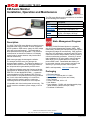
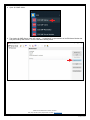
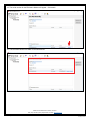
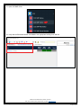
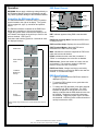
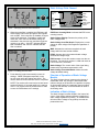
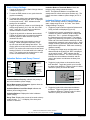
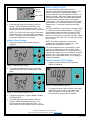
The SCS 770063 EM Aware Monitor empowers you to continuously monitor ESD events, abrupt changes in voltage, and ionizer performance. It features an antenna for detecting and gauging the unique waveform of ESD events, catering to both low and high-temperature settings. This device not only meets the monitoring necessities of ANSI/ESD standards but also complements the Static Management Program (SMP) for comprehensive ESD process control throughout production.
The SCS 770063 EM Aware Monitor empowers you to continuously monitor ESD events, abrupt changes in voltage, and ionizer performance. It features an antenna for detecting and gauging the unique waveform of ESD events, catering to both low and high-temperature settings. This device not only meets the monitoring necessities of ANSI/ESD standards but also complements the Static Management Program (SMP) for comprehensive ESD process control throughout production.


-
 1
1
-
 2
2
-
 3
3
-
 4
4
-
 5
5
-
 6
6
-
 7
7
-
 8
8
-
 9
9
-
 10
10
-
 11
11
-
 12
12
-
 13
13
-
 14
14
-
 15
15
-
 16
16
-
 17
17
-
 18
18


SCS 770063 Installation, Operation and Maintenance Manual
- Type
- Installation, Operation and Maintenance Manual
The SCS 770063 EM Aware Monitor empowers you to continuously monitor ESD events, abrupt changes in voltage, and ionizer performance. It features an antenna for detecting and gauging the unique waveform of ESD events, catering to both low and high-temperature settings. This device not only meets the monitoring necessities of ANSI/ESD standards but also complements the Static Management Program (SMP) for comprehensive ESD process control throughout production.
Ask a question and I''ll find the answer in the document
Finding information in a document is now easier with AI
Related papers
-
SCS CTC034-031-5-WW Installation, Operation and Maintenance Manual
-
SCS 718 User manual
-
-
-
-
-
-
-
-
Other documents
-
AFC CPU-08-G Datasheet
-
AFC CPU-03-G Datasheet
-
 Monroe Electronics 288 Specification
-
-
Greenlee CLAMP-ON GROUND RESISTANCE TESTER User manual
-
-
 Core Insight AirStat 2400 User manual
-
 HOZAN F-66-S / M / L Owner's manual
-
Dwyer Series SCS User manual
-
Desco 19640 Technical Bulletin


