Page is loading ...

INSTALLATION AND PROGRAMMING GUIDE
734N Wiegand
Interface Modules


About the 734N/734N-POE ...................... 1
Power Supply ......................................................... 1
Zone Terminals ...................................................... 1
Annunciators .......................................................... 1
Indicator LEDs ....................................................... 1
Form C Relay ......................................................... 2
Programming Connection ................................ 2
PCB Features ...............................................3
Install the 734N...........................................4
Mount the Device ................................................ 4
Wire the Electronic Lock .................................. 5
Network Connection .......................................... 5
Isolation Relay ...................................................... 8
Install the 333 Suppressor ............................... 9
Wire the Zone Terminals ..................................10
Connect a Card Reader ....................................13
Addressing the 734N ........................................15
TABLE OF CONTENTS
Program the 734N .................................... 17
Program Start Display ......................................18
Initialization Option ...........................................18
Initialize Confirm Option .................................18
Communication Menu .......................................18
734N DHCP ...........................................................19
734N IP Address .................................................19
Subnet Mask .........................................................19
Gateway Address ...............................................19
Panel IP Address .................................................19
Panel IP Port ........................................................20
734N Passphrase ...............................................20
Access Options ..................................................20
Activate Zone 2 Bypass ...................................21
Zone 2 Bypass Time .........................................22
Relock on Zone 2 Change ..............................22
Activate Zone 3 Request to Exit .................23
Zone 3 REX Strike Time .................................. 23
Activate On-board Speaker ..........................24

Custom Card Definitions .........................25
Card Options ....................................................... 25
Wiegand Code Length ....................................26
Site Code Position and Length ....................26
User Code Position and Length ................... 26
Require Site Code .............................................27
Site Code .............................................................. 27
Enter Site Code ..................................................28
Number of User Code Digits .........................28
No Communication with Panel ....................29
Remove Keypad ................................................ 30
Public Card Formats ................................ 31
734N Network Specifications .................32
Compliance Listing Specifications ....... 34
UL Access Control ............................................. 34
ULC Commercial Burglary (XR150/XR550
Series Panels) ...................................................... 34
Certifications .............................................35
Underwriters Laboratory (UL Listed) ........35
International Certifications .....................37
Intertek (ETL) Listed* ......................................37
Export Control .................................................... 37
Product Specifications ............................38
Readers and Credentials ........................ 40

Digital Monitoring Products, Inc. | 734N Installation and Programming Guide 1
ANNUNCIATORS
An on-board programmable piezo provides local
annunciation at the 734N. You can also connect
a variety of switched ground annunciators to the
734N for remote annunciation.
INDICATOR LEDS
The 734N provides three indicator LEDs. The
red LED turns on for the same duration as the
door strike relay. The yellow LED turns on for one
second to indicate receipt of a valid Wiegand
input. The green LED indicates that data is being
sent to the panel.
The 734N and 734N-POE Wiegand Interface Modules allows you to add IP network access control
capability to XR150/XR550 and XR150INT/XR550INT Series panels using proximity credential or
mag-stripe card readers. The modules also allow you to use the powerful built-in access control
capability of DMP Panels.
POWER SUPPLY
The 734N operates at 12/24 VDC from the power
supply supporting a door’s magnetic lock or
door-strike. It can also be powered from POE.
The 734N provides a 10 Amp Form C relay
contact for lock control.
ZONE TERMINALS
Four input zones are provided to allow
connection of nearby burglary devices.
ABOUT THE 734N/734N-POE

2 734N Installation and Programming Guide | Digital Monitoring Products, Inc.
FORM C RELAY
The 734N’s Form C relay draws up to 35 mA of current. See NC/C/NO (Dry Contact Relay) and
Isolation Relay for more information.
PROGRAMMING CONNECTION
The 734N also provides a keypad programming connection that allows you to use a standard DMP
LCD keypad for initial setup. Programming can be completed using a keypad connected to the 734N
or from an XR150/XR550 or XR150INT/XR550INT panel.

Digital Monitoring Products, Inc. | 734N Installation and Programming Guide 3
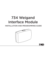
PCB FEATURES
DC INPUT
WIEGAND
INPUTS
ZONES
PIEZO
INDICATOR
LEDS
DOOR RELAY
NETWORK
CONNECTION
Figure 1: PCB Features

4 734N Installation and Programming Guide | Digital Monitoring Products, Inc.
INSTALL THE 734N
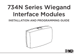
The 734N comes in a high-impact plastic housing that you can mount directly to a wall,
backboard, or other flat surface.
DMP recommends mounting the 734N near the protected door. For easy installation, the back and
ends of the 734N housing have wire entrances. The back also contains multiple mounting holes
that allow you to mount the 734N on a single-gang switch box. See Figure2 for mounting hole
locations on the housing base.
1
MOUNT THE DEVICE
Mounting Hole
Figure 2: Mounting Hole Locations

Digital Monitoring Products, Inc. | 734N Installation and Programming Guide 5
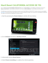
The 734N provides a Form C (SPDT) relay for controlling locks and other electronically-
controlled barriers. The three relay terminals marked NO C NC allow you to connect the device
wiring to the relay for module control.
When the 734N is powered with a 12/24 V power supply or POE, the device can power an
electric strike, up to 750 mA. See Figures 3 and 4 for typical magnetic lock and door strike
wiring. See Figure 5 for POE door strike wiring.
The Form C relay draws up to 35 mA of current and contacts are rated for 10 Amps (resistive)
at 12/24 VDC. When connecting multiple locks to the Form C relay, the total current for all locks
cannot exceed 10 Amps. If the total current for all locks exceeds 10 Amps, problems may arise
and an isolation relay may be needed. See Isolation Relay for more information.
NETWORK CONNECTION
Connect an IP network cable from the LAN/WAN connection to the 734N Network connector.
The 734N communicates AES encrypted TCP with panels that have network installed.
Two LED’s are located on the ethernet jack.
▸ The green LED indicates data sent to the panel.
▸ The yellow LED indicates the speed of the transmission. A solid yellow LED indicates
the network is connected at 100 Base-T. A flashing yellow LED indicates the network is
connected at 10 Base-T.
2
WIRE THE ELECTRONIC LOCK

6 734N Installation and Programming Guide | Digital Monitoring Products, Inc.
PROG
J2
RED RED
KYPD IN
J4
J1
DATA
XMT LED
WIEGAND
READ LED
RELAY
ON
NCCNO
GRNYELRED
Model 333
Supressor
Normally Closed
–
+
Magnetic Door Lock
12/24 VDC
Power Supply
Figure 3: Typical
Magnetic Lock Wiring
PROG
J2
RED
J1
DATA
XMT LED
WIEGAND
READ LED
RELAY
ON
NCCNO
GRNYELRED
Model 333
Supressor
Normally Open
–+
DC Door Strike
12/24 VDC
Power Supply
Figure 4: Typical Door Strike
Wiring with Power Supply

Digital Monitoring Products, Inc. | 734N Installation and Programming Guide 7
Door Strike
POE Switch or Injector
Card Reader
Figure 5: Typical Door
Strike Wiring with POE

8 734N Installation and Programming Guide | Digital Monitoring Products, Inc.
The Form C relay can control a device that draws less than 10 Amps of current. If a device draws
more than 10 Amp of current, or the sum of all devices controlled by the Form C relay exceeds
10 Amps, an isolation relay must be used. Refer to Figures 6 and 7 for isolation relay wiring.
3
ISOLATION RELAY
Figure 6: Magnetic Lock with
an Isolation Relay
Figure 7: Door Strike with
an Isolation Relay
(optional)
Normally
Closed
Magnetic Lock
Model 333
Supressor
–+
12/24VDC
Power
Supply
734N
Interface
Module
DC Input
Model 333
Supressor
Normally
Open
–+
DC Door Strike
12/24VDC
Power
Supply
734N
Interface
Module
DC Input

Digital Monitoring Products, Inc. | 734N Installation and Programming Guide 9
734N
Interface
Module
Model 333
Supressor
Use the included 333 suppressor with the 734N to suppress any surges caused by energizing a
magnetic lock or door strike.
Install the 333 across the 734N C (common) and NO (normally open) or NC (normally closed)
terminals.
If the device being controlled by the relay is connected to the NO and C terminals, install the
suppressor on the NO and C terminals.
Conversely, if the device is connected to the NC and C terminals, install the 333 Suppressor on
NC and C terminals.
The suppressor wire is non-polarized. Install the suppressor as shown in Figure 8.
4
INSTALL THE 333 SUPPRESSOR
Figure 8: 333 Suppressor Installation

10 734N Installation and Programming Guide | Digital Monitoring Products, Inc.
Terminals 5-9 connect grounded zones 1 through 3. These zones have a grounded side and
cannot be used for fire-initiating devices. Zones 2 and 3 can also be used for access control with
Zone 2 providing a bypass option and Zone 3 providing Request to Exit functionality. Zone 4
terminals provide a non-powered Class B, Style A zone. Use the supplied DMP Model 311 1K Ohm
End-of-Line resistors on each zone. Refer to the panel programming guide for programming
instructions. See Figure 9 for more information on wiring the zone terminals.
Auxiliary Outputs 1 & 2
The 734N controls Auxiliary Outputs 1 and 2 when the Activate Zone 2 Bypass programming option
is enabled and the Zone 2 Bypass Time is set. When the door contact (Zone 2) is opened while the
door strike is activated, the Zone 2 Bypass Time starts. If the door has not closed at the end of the
timer, Aux Output 1 is turned on and the timer starts again. If the door is still open at the end of the
second timer, Aux Output 2 is turned on. Aux Outputs 1 and 2 turn o when the door contact is
closed. Use the Model 431 Relay Harness for connection of Output 1 and Output 2.
5
WIRE THE ZONE TERMINALS

Digital Monitoring Products, Inc. | 734N Installation and Programming Guide 11
Figure 9: 734N Zone Terminal
Wiring
Zone 1
Zone 2
Zone 3
Zone 4
1K EOL
1K EOL
1K EOL
1K EOL

12 734N Installation and Programming Guide | Digital Monitoring Products, Inc.
Annunciator Header
The 4-pin header located on the far right of the circuit board is used to wire the Armed Status,
Remote Annunciation, and the Remote LED Control
. The open collectors supply a ground for a
maximum current of 50mA
at 30 VDC.
Connect a Model 300 4-wire harness to the 4-pin header for
connection of the following indicators:
AS (Armed Status)
Armed Status provides an unsupervised switched ground for a visual or audible armed status indicator
that turns on when the burglary areas are armed, such as SYSTEM ON or ALL SYSTEM ON. Connect
the wire from the 4-wire harness to an Armed Status output.
RA (Remote Annunciation)
Remote Annunciation provides an unsupervised switched ground for a remote annunciator that turns
on when the Zone 2 Bypass timer expires.
Connect the wire from the 4-wire harness to a
remote
annunciator. The remote annunciator silences when the RA restores. The remote annunciator (RA)
switched ground operates even if the speaker is programmed not to operate.
LC (Remote LED Control)
Remote LED Control provides an unsupervised switched ground for a visual indicator that turns on
when the 734N relay activates. Connect the wire from the 4-wire harness to an LED. The LED turns
on for the duration the door strike relay is on. HID readers optionally provide a connection for LED
reader control.

Digital Monitoring Products, Inc. | 734N Installation and Programming Guide 13
The 734N provides direct 12/24 VDC, 200 mA output to the reader on the RED terminal
connection. Figure 10 shows a reader with wire colors RED, WHT, GRN, and BLK connecting to
terminals 1, 2, 3, and 4.
The green wire carries Data Zero (D0), and the white wire carries Data One (D1). The red wire
connects 12/24 VDC, 200 mA maximum power and the black wire is ground.
The wire colors may be dierent depending on the reader being installed. Refer to the literature
provided with the reader for wire coding, wire distance, cable type (such as shielded), and other
specifications.
Card Reader LED Operation
To provide visual indication of a valid card read, the card reader can be wired to illuminate the
green LED for the duration of the door strike.
Connect the orange or brown wire to LC to have the green LED stay on for the duration of the
relay activation.
Card Reader Annunciation
Connect the yellow wire to RA to have the remote annunciator turn on anytime the panel
instructs the 734N on-board piezo to turn on.
6
CONNECT A CARD READER
(optional)

14 734N Installation and Programming Guide | Digital Monitoring Products, Inc.
Figure 10: Card Reader Wiring
Card Reader
Red (12/24VDC)
White (Data 1)
Black (GND)
Green (Data 0)
Shield
Orange/Brown
Yellow

Digital Monitoring Products, Inc. | 734N Installation and Programming Guide 15
ADDRESSING THE 734N
Keypad Bus Addresses
DMP XR550 Series panels use keypad bus addresses 1 through 16. XR150 Series panels can only use
keypad bus addresses 1 through 8. Each keypad bus address can accommodate 1 door output and 4
expansion zones. A 734N with an address of 2 on the keypad bus would represent Door 2 and zones
21-24. A 734N with a keypad address of 14 would represent Door 14 and zones 141-144.
AX-Bus Addresses (XR550 only)
DMP XR550 panels are capable of access control expansion using any of the five AX/LX-Bus headers
(AX/LX500, 600, 700, 800, and 900). An AX-Bus address can accommodate 1 door output and 1
expansion zone. Because the 734N has a built-in 4-zone expander, 3 extra zones must be mapped to
the 734. A 734N with an address of 501 on AX500 would represent Door 501 and zones 501-504. A
734N with an address of 505 on AX500 would represent Door 505 and zones 505-508. A 734N with
an address of 701 on AX700 would represent Door 701 and zones 701-704.
Note: Hardwired zone expanders and addressable points and modules do not communicate on
an AX-Bus. AX-Bus doors do not have programmable device or communication types and do
not have assignable display areas.

16 734N Installation and Programming Guide | Digital Monitoring Products, Inc.
Setting the 734N Addresses
Only valid door numbers can be assigned 734N in device setup. For complete keypad and AX-Bus
address mapping, see the chart below.
Table 1: Device Addresses and 734N Zone
Numbers
DEVICE/
DOOR
ZONES
DEVICE/
DOOR
ZONES
DEVICE/
DOOR
ZONES
DEVICE/
DOOR
ZONES
DEVICE/
DOOR
ZONES
DEVICE/
DOOR
ZONES
1 11-14 501 501-504 601 601-604 701 701-704 801 801-804 901 901-904
2 21-24 505 505-508 605 605-608 705 705-708 805 805-808 905 905-908
3 31-34 509 509-512 609 609-612 709 709-712 809 809-812 909 909-912
4 41-44 513 513-516 613 613-616 713 713-716 813 813-816 913 913-916
5 51-54 517 517-520 617 617-620 717 717-720 817 817-820 917 917-920
6 61-64 521 521-524 621 621-624 721 721-724 821 821-824 921 921-924
7 71-74 525 525-528 625 625-628 725 725-728 825 825-828 925 925-928
8 81-84 529 529-532 629 629-632 729 729-732 829 829-832 929 929-932
9 91-94 533 533-536 633 633-636 733 733-736 833 833-836 933 933-936
10 101-104 537 537-540 637 637-640 737 737-740 837 837-840 937 937-940
11 111-114 541 541-544 641 641-644 741 741-744 841 841-844 941 941-944
12 121-124 545 545-548 645 645-648 745 745-748 845 845-848 945 945-948
13 131-134 549 549-552 649 649-652 749 749-752 849 849-852 949 949-952
14 141-144 553 553-556 653 653-656 753 753-756 853 853-856 953 953-956
15 151-154 557 557-560 657 657-660 757 757-760 857 857-860 957 957-960
16 161-164 561 561-564 661 661-664 761 761-764 861 861-864 961 961-964
/