Page is loading ...

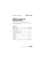
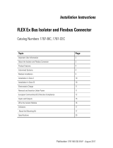
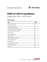
Installation Instructions
Original Instructions
Bulletin 800G Base Mount Back-of-Panel Modules
Catalog Numbers
800G-XB
x
-EX; 800G-DBx-EX; 800G-DBxXx-EX
Product Description
• Contact block (catalog number 800G-XBx-EX)
Contact blocks are used within hazardous areas where machine
functions are activated by pressing a button or actuating a
switch. These contact blocks are designed with self-cleaning
contacts and N.O. contacts feature positive break operation.
Contact blocks are compatible with all 800G non-illuminated
operators.
• Power module (catalog number 800G-DBx-EX)
Power modules are used within hazardous areas to indicate the
functional status of respective machines visually by lighting up
or turning off. Power modules are compatible with all 800G
pilot light operators.
• Power module with contact block (catalog number
800GDBxXx-EX)
Power module with contact block combination units are used
within hazardous areas where machine functions are activated
by depressing a push button and the corresponding functional
status is visually indicated. These units are compatible with all
800G illuminated push button operators.
ATTENTION: To help prevent electrical shock, disconnect from
power source before installing or servicing. Follow NFPA 70E
requirements. Install in suitable enclosure. Keep free from
contaminants.
Only suitably trained personnel can install, adjust, commission,
use, assemble, disassemble, and maintain the product in
accordance with applicable code of practice. If a malfunction or
damage occurs, do not attempt to repair the product.
IMPORTANT When working in hazardous areas, the safety of personnel
and equipment depends on compliance with the relevant
safety regulations. The people in charge of installation and
maintenance bear a special responsibility. They must be
knowledgeable of the applicable rules and regulations.
These instructions provide a summary of the most important
installation measures. Everyone working with the product
must read these instructions so that they are familiar with the
correct handling of the product.
Keep these instructions for future reference as they must be
available throughout the expected life of the product.
Contact Block (Screw Termination) Power Module (Screw Termination)
Power Module with Contact Block
(Screw Termination)
Certifications
ATEX CML 17 ATEX 1107 U CML 17 ATEX 1108 U
IECEx IECEx CML 17.0047U IECEx CML 17.0048U
NEPSI GYJ17.1398U GYJ17.1399U
INMETRO UL-BR 14.0567U UL-BR 14.0566U
Gas protection type II 2 G Ex db eb IIC Gb
Ambient Temperature Range
-55…+40 °C (-67…+104 °F) @ 16 A
-55…+60 °C (-67…+140 °F) @ 11 A
-55…+50 °C (-67…+122 °F) or 60 °C (140 °F) if U
e
≤26.4V
Service Temperature Range -55…+85 °C (-67…+185 °F)
Mechanical and Electrical Ratings
Rated Insulation Voltage 690V 300V
Power Consumption — ≤1 W
Rated Voltage (U
e
) AC 250V and 400V; DC 24V and 110V
•T
a
<50 °C (122 °F): 12…250V AC, 12…60V DC
•T
a
<60 °C (140 °F): 12…24V AC/DC
Illumination Colors (LED) — Red, green, blue, white, or yellow
Contact Options 1 N.O./1 N.C., 2 N.O., 2 N.C. — 1 N.O., 1 N.C.
Utilization Category (AC) AC-12: 16 A, 400V; AC-15: 10 A, 400V — AC-15: 1 A, 230V
Utilization Category (DC) DC-13: 1 A, 24V; DC-13: 0.5 A, 110V — DC-13: 0.25 A, 24V
Conventional Thermal Current (I
the
)
16 A/40 °C (104 °F)
11 A/60 °C (140 °F)
——
Conductor Size 0.75…2.5 mm² (18…14 AWG)
Degree of Protection
• Module only: IP20
• Module and operator: IP64/IP66

2 Rockwell Automation Publication 800G-IN002B-EN-P - May 2018
Bulletin 800G Base Mount Back-of-Panel Modules
Additional Contact Block and Power Module
Information
Front-of-panel operators are inserted into a mounting hole in an “Ex e”
enclosure or control panel. The respective back-of-panel module is
mounted directly underneath the operator by latching onto a DIN
mounting rail (NS 357.5).
The conductor connection is made by wiring the conductors to
terminals at the back of the contact block, power module, or power
module with contact block combination unit.
Compatibility
Contact blocks, power modules, and power module with contact block
combination units are compatible with specific front-of-panel
operators.
Safety Instructions
Improper installation can cause malfunctioning and the loss of
explosion protection.
All back-of-panel modules and operators can only be used within the
specified ambient temperature range (depending on the voltage and
current).
Use in areas other than those areas specified or the modification of the
product by anyone other than the manufacturer is not permitted and
exempts Rockwell Automation from liability for defects and any
further liability.
The applicable statutory rules and other binding directives that relate
to workplace safety, accident prevention, and environmental
protection must be observed.
Before you commission or restart operation, check compliance with all
applicable laws and directives.
All back-of-panel modules can be used only if they are in a clean and
undamaged condition. Do not modify these modules in any way.
Standards Conformed To
Assemble, Install, and Commission
• Only qualified personnel are allowed to assemble, disassemble,
install, and commission the device.
• Protect devices against mechanical damage or electrostatic
discharge.
• Use suitable tools and install cable firmly.
• Use cable that is rated with an appropriate temperature range
suitable for the application.
Assemble and Disassemble
To mount the contact block or power module, follow these steps:
1. Verify that the contact block or power module is intact (no
cracks).
2. Confirm the back-of-panel module is compatible with the
installed operator (see Compatibility
).
3. Position the contact block or power module on the mounting
DIN rail.
4. Align the position of the contact block or power module on
the mounting DIN rail at the front-of-panel operator.
Back-of-Panel Front-of-Panel
Contact block Non-illuminated operator
Power module Pilot light
Power module and contact block Illuminated push button
• EN 60079-0 • EN 60079-1 • EN 60079-7
• IEC 60079-0 • IEC 60079-1 • IEC 60079-7
ATTENTION: Risk of serious injury due to incorrect assembly,
installation, and commissioning.
IMPORTANT The contact block in the following diagram serves as an
example of all back-of-panel modules.
35
(1.4)
7.5
(0.3)
72.5 (2.9)
NS 35/7.5
Measurements are shown in mm (in.)

Rockwell Automation Publication 800G-IN002B-EN-P - May 2018 3
Bulletin 800G Base Mount Back-of-Panel Modules
Installation
In hazardous areas, the contact block or power module must be used:
• In appropriate enclosures with “Ex e” increased safety type of
protection. The clearance and creepage distances under IEC/
EN 60079-7 Clauses 4.3 and 4.4 must be observed.
• In an enclosure that corresponds to another approved type of
protection that is specified in IEC/EN 60079-0 Clause 1.
Take care when following these steps to connect the cable:
1. Strip 40 mm (1.575 in.) of sheath off the cable.
2. Remove approximately 6 mm (0.236 in.) of insulation from the
conductors.
3. Prepare the ends of the fine-stranded and multi-stranded
conductors. Crimp wire end sleeves with suitable crimp tools.
Connection cross-sections: 0.75…2.5 mm (18…14 AWG).
4. Open terminal cage and insert conductors.
5. Tighten the terminals to a torque range of 0.4…0.7 N·m
(3.5…6.2 lb·in).
Commissioning
Before commissioning, check the following:
• The device has been installed in compliance with the
regulations.
• The device is not damaged.
• The connection has been established properly (verify that the
conductors are secure).
Maintenance
• Only qualified personnel are allowed to do any maintenance
and fault clearance.
• IEC/EN 60079-17 must be observed.
You must keep the contact block and power module devices in good
condition, operate them properly, monitor them, and clean them
regularly.
• Check all contact blocks, power modules, operators, and cables
regularly for cracks and damage. Verify that they are properly
installed.
Repair and Replacement
• Back-of-panel devices are defective if the contact block does
not function properly or the status indicator does not
illuminate on the power module.
• Devices must be replaced with an equivalent catalog number
from the manufacturer.
Accessories and Replacement Parts
For more accessories and replacement parts that Rockwell Automation
offers, see https://ab.rockwellautomation.com/Push-Buttons/
Hazardous-Location/800G.
Disposal
At the end of its life, this equipment must be collected separately from
any unsorted municipal waste. Follow all local and national
requirements for disposal of this product.
Terminals
Contact Block
1 N.O. and 1 N.C. Contact 2 N.C. Contacts 2 N.O. Contacts
Power Module
Power Module with Contact Block
1 N.O. 1 N.C.
13
14
21
22
11
12
21
22
13
14
23
24
X1
X2
3
4
X1
X2
1
2
X1
X2
ATTENTION: Risk of serious injury due to incorrect maintenance.
IMPORTANT Do not clean contact blocks, power modules, or power
module with contact block combination units with
compressed air.
ATTENTION: Defective contact blocks and power modules cannot
be repaired; they must be replaced.

Allen-Bradley, Rockwell Automation, and Rockwell Software are trademarks of Rockwell Automation, Inc.
Trademarks not belonging to Rockwell Automation are property of their respective companies.
Rockwell Otomasyon Ticaret A.Ş., Kar Plaza İş Merkezi E Blok Kat:6 34752 İçerenköy, İstanbul, Tel: +90 (216) 5698400
Rockwell Automation maintains current product environmental information on its website at
http://www.rockwellautomation.com/rockwellautomation/about-us/sustainability-ethics/product-environmental-compliance.page
.
EEE Yönetmeligine Uygundur.
Publication 800G-IN002B-EN-P - May 2018 10001129327 Ver 02
Supersedes Publication 800G-IN002A-EN-P - April 2015 Copyright © 2018 Rockwell Automation, Inc. All rights reserved. Printed in the U.S.A.
Approximate Dimensions
Dimensions are shown in millimeters (inches).
Contact Block
(Catalog Number 800G-XBx-EX)
Power Module
(Catalog Number 800G-DBx-EX)
Power Module with Contact Block
(Catalog Number 800G-DBxXx-EX)
Declaration of Conformity
Rockwell Automation, Inc. declares that the 800G-XBx-EX,
800GDBx-EX, and 800G-DBxXx-EX Series A base mount contact
blocks, power modules, and power module with contact block units are
in compliance with Essential Health and Safety Requirements of
Directive 2014/34/EU (ATEX) as follows:
• Equipment Group II, Equipment Category 2
• Type of Protection “Ex db eb IIC Gb”
• Compliance to standards EN 60079-0:2012+A11:2013,
EN 60079-1:2014, and EN 60079-7: 2015 per ATEX Type
Examination Certificates CML 17ATEX1107U and
CML 17ATEX1108U
The full text of the EU declaration of conformity is available at the
following website:
http://www.rockwellautomation.com/global/certification
0.5 (0.02)
52 (2.05)
46
(1.81)
33.5 (1.32)
57.5
(2.25)
33.5 (1.32)
57.5
(2.25)
52 (2.05)
91 (3.58)
46
(1.81)
Ø 19
(0.75)
33.5 (1.32)
57.5
(2.25)
52 (2.05)
84 (3.31)
46
(1.81)
Ø 19
(0.75)
/