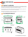
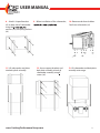
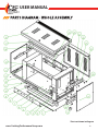
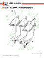
CPG 351S36SBL36K is a 36" gas salamander broiler that allows you to quickly and easily brown the top of casseroles, melt cheese, toast sandwiches, or even finish steaks and other meats! It is equipped with a gas-fired 36,000 BTU atmospheric infrared burner with an adjustable gas valve and a continuous pilot for instant ignition. The salamander features a sleek stainless steel front and sides, making it both durable and easy to clean! A full width, large capacity broiler pan can also be removed for convenient cleaning.
CPG 351S36SBL36K is a 36" gas salamander broiler that allows you to quickly and easily brown the top of casseroles, melt cheese, toast sandwiches, or even finish steaks and other meats! It is equipped with a gas-fired 36,000 BTU atmospheric infrared burner with an adjustable gas valve and a continuous pilot for instant ignition. The salamander features a sleek stainless steel front and sides, making it both durable and easy to clean! A full width, large capacity broiler pan can also be removed for convenient cleaning.


-
 1
1
-
 2
2
-
 3
3
-
 4
4
-
 5
5
-
 6
6
-
 7
7
-
 8
8
-
 9
9
-
 10
10
-
 11
11
-
 12
12
-
 13
13
-
 14
14
-
 15
15
-
 16
16
-
 17
17
-
 18
18
-
 19
19


CPG 351S36SBL36K is a 36" gas salamander broiler that allows you to quickly and easily brown the top of casseroles, melt cheese, toast sandwiches, or even finish steaks and other meats! It is equipped with a gas-fired 36,000 BTU atmospheric infrared burner with an adjustable gas valve and a continuous pilot for instant ignition. The salamander features a sleek stainless steel front and sides, making it both durable and easy to clean! A full width, large capacity broiler pan can also be removed for convenient cleaning.
Ask a question and I''ll find the answer in the document
Finding information in a document is now easier with AI
Related papers
-
CPG 351S36SBN36K User manual
-
CPG 351FGCs Powered Convection Ovens100DD Deep Depth Ga User manual
-
CPG 351WOKNG 13 Inch Natural Gas Wok Range User manual
-
CPG 351EF300 User manual
-
CPG CK-HPSU212 Gas Step Up Hot Plate User manual
-
CPG CK-HPSU212 Boasting 6 Powerful 30000 BTU Burners User manual
-
CPG 351CPGDSPRN User manual
-
CPG 351SR12NL Countertop Step Up Ranges User manual
-
-
CPG 351WOKR13 User manual
Other documents
-
COOKING PERFORMANCE GROUP 351RCPG36NL User manual
-
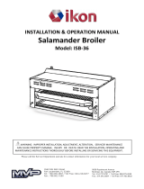 IKON ISB-36 Owner's manual
-
COOKING PERFORMANCE GROUP 351EF300 User manual
-
Pantheon SG630 Owner's manual
-
Southbend S-60 Owner's manual
-
-
Garland MST54 Owner Instruction Manual
-
Garland G Series User manual
-
Market Forge 99-5702 Operating instructions
-
U.S. Range M42 M42R M42T M42S Specification
