Page is loading ...

SHIPPING, RIGGING, HOISTING AND ASSEMBLY MANUAL
ENERGY RECOVERY VENTILATORS
RENEWAIRE.COM
LE6X
LE8X
LE10X

SHIPPING, RIGGING, LIFTING AND ASSEMBLY: LE MODELS
RENEWAIRE.COM INSTALLATION, OPERATION AND MAINTENANCE MANUAL 1.800.627.44992
IMPORTANT SAFETY INFORMATION
WARNING
RISK OF DEATH 0R SERIOUS INJURY
Hoisting heavy equipment overhead is inherently dangerous.
Failure to properly rig the ERV for hoisting or the use of incorrect
rigging equipment may result in the ERV falling during hoisting.
Improper work procedures may result in death or serious injury
to workers. Rigging, hoisting and assembly are to be performed
by skilled and experienced personnel. OSHA-approved work
guidelines are to be strictly followed.
Before proceeding with installation, read all instructions,
verifying that all the parts are included.
The information in this manual is provided as a guideline and
does not neccessarily meet all local codes. It is the installer’s
responsibility to comply with all local codes and OSHA-approved
safety practices.
RISK OF DAMAGE TO ENTHALPIC CORES
Whenever working within the ERV cabinet, protect the enthalpic
cores from accidental damage. The core media is subject to
damage from dropped tools or other foreign objects.
RISK OF DAMAGE TO ERV CABINET
Incorrect lifting can cause damage to the unit.
Do not lift joined unit by the 4 corner lifting lugs only. Secure
lifting cables to the center lifting lugs also.
All lifting lugs provided must be used. Never lift the unit or
modules from the top of the unit.
This unit is intended for general ventilating only. Do not use to
exhaust hazardous or explosive materials and vapors. Do not
connect this equipment to range hoods, fume hoods or collection
systems for toxics.
This unit is for ventilating finished structures only. It is not to
be used until after all construction has been completed and
construction debris and dust are cleaned from the Occupied
Space.
Do not lift joined unit by the 4 corner lifting lugs only. Secure
lifting cables to the center lifting lugs also.
All lifting lugs provided must be used. Never lift the unit or
modules from the top of the unit.
Incorrect lifting can cause damage to the unit.
This equipment is to be installed by following Industry Best
Practices and all applicable codes. Any damage to components,
assemblies, subassemblies or the cabinet which is caused by
improper installation practices will void the warranty.
NOTICE
NOTICE
NOTICE
NOTICE
NOTICE
NOTICE
IMPORTANT IMPORTANT
If this unit is installed in an area where it may draw air from
a nearby fuel-burning device such as a gas furnace or water
heater, verify that the air being extracted by the ERV does not
conflict with proper operation of the fuel-burning device.
This unit can be delivered in two modules for on-site assembly
or as a completely assembled unit (additional charges apply).
See separate unit-specific Installation, Operation and
Maintenance manual for further information.

SHIPPING, RIGGING, LIFTING AND ASSEMBLY: LE MODELS
3 1.800.627.4499 INSTALLATION, OPERATION AND MAINTENANCE MANUAL RENEWAIRE.COM
OWNER INFORMATION
IMPORTANT USER INFORMATION
READ AND SAVE THIS MANUAL/LIRE ET CONSERVER CE MANUEL
In the unlikely event that factory assistance is ever required, information located on the unit label will
be needed.
UNIT INFORMATION
Configuration (Option) Code
Unit Label (typical)

SHIPPING, RIGGING, LIFTING AND ASSEMBLY: LE MODELS
RENEWAIRE.COM INSTALLATION, OPERATION AND MAINTENANCE MANUAL 1.800.627.44994
OWNER INFORMATION
TABLE OF CONTENTS
UNIT INFORMATION 3
1.0 SHIPPING 6
1.1 RECEIVING AND HANDLING 6
1.2 STORAGE BEFORE INSTALLATION 6
2.0 RIGGING 7
2.1 REQUIRED RIGGING EQUIPMENT 7
3.0 FORKLIFT REQUIREMENTS 9
4.0 MODULE ASSEMBLY 9
4.1 CONFIGURATION LABEL 9
4.2 ASSEMBLY PREPARATION 9
4.3 REMOVE SHIPPING STRAPS 10
4.4 APPLY FOAM GASKET TAPE 10
4.5 JOIN MODULES TOGETHER 11
4.5.1 Bolt Together at Lifting Lugs 11
4.5.2 Bolt Together Mating Roof Beams 12
4.5.3 Caulk The Seams 13
4.5.4 Install Joining Roof Cap 13
4.5.5 Install Assembly Straps 14
4.5.6 Install Roof End Joining Caps 14
4.6 CONNECT THE WIRING HARNESS 15
4.7 INSTALL WEATHERHOODS 16
4.8 INSTALL MERV-8 FILTERS 17
5.0 ROOFTOP CURB DIMENSIONS 18
5.1 LE6XRT CURBS 18
5.2 LE8XRT CURBS 18
5.3 LE10XRT CURBS 19
6.0 ROOFTOP UNIT DIMENSIONS 20
6.1 LE6XRTH-F DIMENSION DRAWING 20
6.2 LE6XRTV-R DIMENSION DRAWING 20
6.3 LE8XRTH-F DIMENSION DRAWING 21
6.4 LE8XRTV-R DIMENSION DRAWING 21
6.5 LE10XRTH-F DIMENSION DRAWING 22
6.6 LE10XRTV-R DIMENSION DRAWING 22
7.0 INDOOR UNIT DIMENSIONS 23
7.1 LE6XINH DIMENSION DRAWING 23
7.2 LE6XINV DIMENSION DRAWING 23
7.3 LE8XINH DIMENSION DRAWING 24
7.4 LE8XINV DIMENSION DRAWING 24
7.5 LE10XINH DIMENSION DRAWING 25
7.6 LE10XINV DIMENSION DRAWING 25
8.0 LE6X CORNER WEIGHTS 26
8.1 LE6XRT CORNER WEIGHTS 26
8.2 LE6XINH CORNER WEIGHTS 27
8.3 LE6XINVH CORNER WEIGHTS 27
9.0 LE8X CORNER WEIGHTS 28
9.1 LE8XRT CORNER WEIGHTS 28
9.2 LE8XINH CORNER WEIGHTS 29
9.3 LE8XINVH CORNER WEIGHTS 29
10.0 LE10X CORNER WEIGHTS 30
10.1 LE10XRT CORNER WEIGHTS 30
10.2 LE10XINH CORNER WEIGHTS 31
10.3 LE10XINVH CORNER WEIGHTS 31

SHIPPING, RIGGING, LIFTING AND ASSEMBLY: LE MODELS
5 1.800.627.4499 INSTALLATION, OPERATION AND MAINTENANCE MANUAL RENEWAIRE.COM
TABLE OF ILLUSTRATIONS
Unit Label (typical) 3
LE ERV Hood Shipping Location (typ) 6
Rigging Assembly Graphic 1 8
Rigging Assembly Graphic 2 8
Corner Lifting Lug (typ) 8
Shipping Straps Location 10
Foam Gasketing Tape Location (typ) 10
Module Positioning Technique 11
LE Indoor Unit Base Bolt Locations 11
LE Rooftop Unit Base Bolt Locations 11
Alignment / Spacer Bolt Location 11
Roof Beam Assembly Graphic 2 12
Roof Beam Assembly Graphic 1 12
Roof Beam Assembly Bolt Locations 12
Roof Cap Caulking 13
Roof Beam Caulking 13
Assembly Strap Locations 14
Roof End Joining Caps 14
Assembly Strap Installation 14
Wiring Harness Access Panel 15
Wiring Harness Routing 15
Access Panel Removal 15
Wiring Harness Connections 15
OA Hood Screw Locations 16
EA Hood Screw Locations 16
Access Panel Installation 16
OA Hood Installation 16
EA Hood Installation 16
Filter Spacers 17
Filter Racks 17
Filter Extractor Hook 17

SHIPPING, RIGGING, LIFTING AND ASSEMBLY: LE MODELS
RENEWAIRE.COM INSTALLATION, OPERATION AND MAINTENANCE MANUAL 1.800.627.44996
SHIPPING
1.0 SHIPPING
1.1 RECEIVING AND HANDLING
1.2 STORAGE BEFORE INSTALLATION
All ERVs are palletized and then shipped by common carrier. It is the installer’s / customer’s
responsibility to coordinate delivery and properly handle the shipment during unloading and storage.
Upon delivery of the ERV, inspect it carefully for shipping damage and completeness. Verify the pres-
ence of any accessories such as external hoods that are to be field-installed or filters that are shipped
loose. If shipping damage is discovered, take digital pictures and note the visible damage on the ship-
ping manifest. Notify your RenewAire dealer immediately.
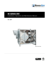
Note that whenever possible, accessories such as weather hoods are assembled and then secured for
shipping inside the ERV. See photo below.
LE ERV Hood Shipping Location (typ)
Hoods are assembled at the factory and
then secured for shipment inside the ERV.
LE models can be delivered in two modules for on-site assembly or as a complete unit (additional
charges apply).
In all cases, extra protective pallet materials may have been added; this material was added at the
factory to protect the unit or modules during shipping.
In all cases, when shipped as modules, assembly materials ship loose and can be found inside the
modules. Note that assembly materials must be removed and installed prior to unit operation.
For rooftop models, the outdoor air weather hoods ship loose and can be found inside the modules.
Note that weather hoods and assembly materials must be removed and installed prior to unit operation.
If installation will not occur immediately following delivery, store equipment in a dry protected area
away from construction traffic and in the proper orientation as marked on the packaging with all in-
ternal packaging in place.
When placing the ERV on the ground, the placement area should be flat and level. Take care to avoid
twisting or wracking of the unit.

SHIPPING, RIGGING, LIFTING AND ASSEMBLY: LE MODELS
7 1.800.627.4499 INSTALLATION, OPERATION AND MAINTENANCE MANUAL RENEWAIRE.COM
RIGGING
2.0 RIGGING
2.1 REQUIRED RIGGING EQUIPMENT
The unit comes equipped with base rail lifting lugs at the lower 4 corners and in the middle of the unit.
Each lifting lugs come equipped with a 2” diameter hole which will accommodate a 1.5” dia. schedule
40 steel pipe (not provided).
Unit or module sections shall be lifted by cables attached to all of the lifting lugs.
If cables or chains are used to lift the unit they must be the same length. Care should be taken not to
damage the cabinet, dampers, or electrical box.
Adjustable spreader bars should be used to properly support the unit in order to properly distribute
the load thus applying an even vertical lifting force to all of the lifting lugs. This will prevent structural
damage to the unit.
Also adjustable spreader bars should be used to maintain the required 10” clearance between the
cables and the cabinet or any of the equipment attached to the unit or modules.
Provide additional blocking or covering as required.
Secure hooks and cables at all lifting points.
Take up slack in cables gradually as to avoid sudden movements as this may cause the unit or modules
to shift.
Suspending the unit or modules for an extended period of time is not recommended and it is advised
to place the unit as soon as possible after lifting.
Do not lift in high winds.
RenewAire will not be responsible for any damage during the rigging, lifting or installing of the unit or
modules.
Refer to Corner Weight Charts for exact center of gravity.
All rigging equipment is to be provided by the installing Contractor.
Rigging procedures may differ depending on the physical dimensions of the unit or modules, it’s loca-
tion, the job site, or Installing Contractor preferences.
Tools needed (Suggested):
Crane to lift proper capacity
Adjustable spreader bars
Cables
1.5” Dia. steel pipe schedule 40.
Tools to pull modules together, chains, bar clamps, come alongs etc.
Miscellaneous (SAE) wrenches and 1/2” drive socket wrenches with short extensions

SHIPPING, RIGGING, LIFTING AND ASSEMBLY: LE MODELS
RENEWAIRE.COM INSTALLATION, OPERATION AND MAINTENANCE MANUAL 1.800.627.44998
RIGGING
Corner Lifting Lug (typ)
Rigging Assembly Graphic 1
Rigging Assembly Graphic 2

SHIPPING, RIGGING, LIFTING AND ASSEMBLY: LE MODELS
9 1.800.627.4499 INSTALLATION, OPERATION AND MAINTENANCE MANUAL RENEWAIRE.COM
ASSEMBLY
3.0 FORKLIFT REQUIREMENTS
4.0 MODULE ASSEMBLY
When lifting individual modules, forklift extensions must be used and a minimum length of 72” (96”
preferred).
When lifting modules off the pallets:
If entering from the door side or the open side of the module ensure forks extend in far enough as to
catch the furthest away stringer with fork extensions.
If entering from the side of the module, insure forks extend all the way through the module.
NOTICE
Do not attempt to lift a rooftop module off the pallet from the door side or open side as there are no
stringers under the unit to carry the load.
Assembled modules should never be lifted using a forklift.
4.1 CONFIGURATION LABEL
4.2 ASSEMBLY PREPARATION
RenewAire LE series Energy Recovery Ventilators can either be built and shipped factory assembled or
be ordered unassembled for applications where modules must be manipulated separately. If the unit
was ordered unassembled, then you will need to assemble the modules in the field.
Each module is labeled with a configuration and serial number label. Locate these labels and insure
each module assembled together have the same configuration and serial number. See the image on
page 3 of this manual.
If for any reason you are unable to identify a module or its position in the final assembly, then consult
the Installation Contractor or RenewAire Customer Service.
Extra protective pallet material has to be removed prior to assembly. This additional pallet material
was added at the factory to protect the unit during shipping.
Also, plywood protective packaging material has to be removed from modules before assembly.
It is desirable to situate all required modules in the installation location as near as possible to the order
in which they will be connected. Be sure to leave enough space to work between modules before
connection. Gasket tape will be applied before assembling the modules.
All materials for assembling the modules are supplied by RenewAire.

SHIPPING, RIGGING, LIFTING AND ASSEMBLY: LE MODELS
RENEWAIRE.COM INSTALLATION, OPERATION AND MAINTENANCE MANUAL 1.800.627.449910
ASSEMBLY
4.3 REMOVE SHIPPING STRAPS
4.4 APPLY FOAM GASKET TAPE
Remove shipping straps from opening/mating ends before joining modules and operating the unit.
Shipping straps are attached to the modules at the factory. These straps insure proper rigidity when
shipping and lifting. Once the straps are removed they may be disposed of along with the screws that
held them in place.
www.renewaire.com (800) 627- 4499 [email protected]
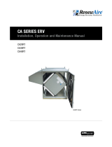
Apply 1/2” X 1” gasket tape (provided), as shown below. Gasket tape creates an airtight seal between
modules. The adhesive backing on the gasket tape is easily repositioned during assembly if needed.
However, if gasket tape is allowed to set more than 48 hours, it will be difficult to reposition.
INSTALL FOAM GASKETING
TAPE AS SHOWN HERE.
(Gasketing is shown in red for
clarity)
NOTE: Failure to apply
foam gasketing tape
as shown here will
compromise water and
airtight seal of the unit.
Foam Gasketing Tape Location (typ)
Shipping Straps Location

SHIPPING, RIGGING, LIFTING AND ASSEMBLY: LE MODELS
11 1.800.627.4499 INSTALLATION, OPERATION AND MAINTENANCE MANUAL RENEWAIRE.COM
ASSEMBLY
4.5 JOIN MODULES TOGETHER
4.5.1 Bolt Together at Lifting Lugs
Align modules and push together using forklift or other means, compressing the gasket tape. The
lower lifting lugs are equipped with 2” diameter holes that 1.5” dia. (2” OD) steel pipe could be used
to assist in alignment. See Lifting Lug illustration on page 8 of this manual. Joining lift lugs also have a
spacing bolt at the tip of one lug that will fit into the empty lug hole of the other module for alignment
and lug tip spacing.
After positioning the modules together, compressing the gasket tape, insert eight 3/8” - 16 x 1-1/4
plated hex head bolts through the holes on the lifting lugs and base rail (LE-IN) or base supports
(LE-RT) of the two adjacent modules. Use 3/8” washers between the bolt head and the unit and
between the nut and the unit. Fasten the nuts to the bolts secure the bases of the two modules
together tightly.
ALIGNMENT /
SPACER
BOLT
LE INDOOR UNITS:
INSTALL 2 BOLTS IN THE MATING LIFT-
ING LUGS AND THEN 2 MORE BOLTS
IN THE MATING BASE RAILS. TYPICAL
EACH SIDE OF LE UNIT.
2 BOLTS THROUGH LIFTING
LUGS (EACH SIDE OF UNIT)
HAND HOLES (TYP, EACH
SIDE OF UNIT)
2 BOLTS THROUGH LIFTING
LUGS (EACH SIDE OF UNIT)
2 BOLTS THROUGH BASE RAILS (EACH SIDE
OF UNIT). ACCESS BOLT AND NUT THROUGH
THE HAND HOLES IN EACH MODULE SIDE BASE
RAIL TO BE JOINED.
2 BOLTS THROUGH BASE SUP-
PORTS (EACH SIDE OF UNIT).
ACCESS BOLT AND NUT
THROUGH HAND HOLES IN
EACH MODULE SIDE BASE RAIL
TO BE JOINED.
LE ROOFTOP UNITS:
INSTALL 2 BOLTS IN THE
MATING LIFTING LUGS AND
THEN 2 MORE BOLTS IN BASE
SUPPORT.
LE Indoor Unit Base Bolt Locations
LE Rooftop Unit Base Bolt Locations
Alignment / Spacer Bolt LocationModule Positioning Technique

SHIPPING, RIGGING, LIFTING AND ASSEMBLY: LE MODELS
RENEWAIRE.COM INSTALLATION, OPERATION AND MAINTENANCE MANUAL 1.800.627.449912
ASSEMBLY
4.5.2 Bolt Together Mating Roof Beams
Use bar clamps, or other non-destructive winching device to pull the top of the modules together tightly
compressing the gasket. After aligning the 4 roof bolt locations, insert 1/4” - 20 x 1.00” Grade 5 zinc
plated hex head bolts through the holes in the roof beam. Secure the nuts to secure the roof section.
www.renewaire.com (800) 627- 4499 [email protected]
AFTER THE LIFTING LUG AS-
SEMBLIES HAVE BEEN BOLTED
TOGETHER, RAISE ONE END OF
THE UNIT TO COMPRESS THE
GASKETING AND BRING BOTH
OF THE MATING ROOF BEAMS
INTO TIGHT CONTACT.
USE A PIPE CLAMP TO ADJUST
THE ROOF BEAMS LATERALLY
AND THEN BOLT TOGETHER
THE TWO ROOF BEAMS.
Roof Beam Assembly Graphic 1
Roof Beam Assembly Graphic 2
Roof Beam Assembly Bolt Locations

SHIPPING, RIGGING, LIFTING AND ASSEMBLY: LE MODELS
13 1.800.627.4499 INSTALLATION, OPERATION AND MAINTENANCE MANUAL RENEWAIRE.COM
ASSEMBLY
4.5.3 Caulk The Seams
4.5.4 Install Joining Roof Cap
Attention should be taken to assure the modules are forming an air and water tight seal.
Apply a continuous ½” bead of Tremsil 600 Silicone Sealant caulk (provided) at the seam along the
entire roof and sides of the unit.
A galvanized cap roof flange is provided to seal the roof seam and to maintain a water and airtight seal.
The cap roof flange is provided with pre-drilled holes. #12 X .75 hex head tek screw w/washers are
provided to attach the cap roof flange.
For best results, use a lower torque setting on the power drill. Be careful not to over tighten the screw.
NOTE: Failure to apply
caulk in these locations
will compromise the
water and airtight seal
of the unit.
NOTE: Failure to
install the roof cap will
compromise the water
and airtight integrity of
the unit.
Roof Beam Caulking
Roof Cap Caulking

SHIPPING, RIGGING, LIFTING AND ASSEMBLY: LE MODELS
RENEWAIRE.COM INSTALLATION, OPERATION AND MAINTENANCE MANUAL 1.800.627.449914
ASSEMBLY
4.5.5 Install Assembly Straps
4.5.6 Install Roof End Joining Caps
Two (2) galvanized metal assembly straps are used to secure the module seams to assist in maintain-
ing a water and airtight seal and provide structural rigidity during lifting. One (1) used on each side of
the unit. These straps are provided with pre-drilled holes. #12 X 3/4” hex head tek screw w/washers
are provided to attach the joining straps to the unit. For additional protection, caulk sides of straps
after attachment.
For best results, use a lower torque setting on the power drill. Be careful not to over tighten the screw.
www.renewaire.com (800) 627- 4499 [email protected]
Two (2) galvanized roof cap ends are provided to seal the top end of each module and maintain a water
and airtight seal. The roof cap joining ends are provided with pre-drilled holes. #12 X 3/4” hex head
tek screw w/washers are provided to attach these roof cap joining ends to the unit.
www.renewaire.com (800) 627- 4499 [email protected]
NOTE: Failure to install the assembly straps will
compromise the structural integrity of the unit and
cause damage during lifting. It will also compromise
the water and airtight integrity of the unit.
NOTE: Failure to install roof cap ends will compromise
the structural integrity of the unit and cause unit
damage during lifting. It will also compromise the water
and airtight integrity of the unit.
Assembly Strap Locations Assembly Strap Installation
Roof End Joining Caps

SHIPPING, RIGGING, LIFTING AND ASSEMBLY: LE MODELS
15 1.800.627.4499 INSTALLATION, OPERATION AND MAINTENANCE MANUAL RENEWAIRE.COM
ASSEMBLY
4.6 CONNECT THE WIRING HARNESS
Wiring Harness Access Panel
Wiring Harness Routing
Access Panel Removal
Wiring Harness Connections
Internal wiring connections are required after modules are fastened together, and before connection
of unit supply power. For INH and RT models, the back module comes pre-wired with the exhaust air
blower wires being routed from the motor to the open end of the module. The wiring harnesses end in
plugs, ready for connection.
If the back module is equipped with isolation dampers, they are also pre-wired with the damper wires
being routed from the damper actuators to the open end of the module. The ends of the damper wiring
harnesses also end in plugs, ready for connection.
After the modules are joined together, open the electrical connection cover on the E-Box side of the
front module by removing screws in the access panel. The access panel is located in the upper left
corner of the front module, to the left of the E-Box.
www.renewaire.com (800) 627- 4499 [email protected]
www.renewaire.com (800) 627- 4499 [email protected]
Inside the access panel are low voltage and high voltage wiring connection compartments. The low
voltage compartment is the lower compartment and the high voltage compartment is the upper
compartment. Both compartments are open on the left side to access the wiring harness plugs that are
coming from the exhaust air blower and isolation dampers (if equipped).
Reach through the open left side of the compartments and into the rear module. Guide the wiring
harness(es) into the wiring connection compartments in the front module. Plug each wiring harness
into its matching connector, located in the wiring connection compartments. Secure excess wire with
wire ties.

SHIPPING, RIGGING, LIFTING AND ASSEMBLY: LE MODELS
RENEWAIRE.COM INSTALLATION, OPERATION AND MAINTENANCE MANUAL 1.800.627.449916
ASSEMBLY
4.7 INSTALL WEATHERHOODS
Rooftop units (RT models) have weatherhoods that are shipped loose and must be field-installed.
Installation of the hoods is normally performed after all rigging and hoisting is completed because of
the chance of damage to the hoods by the rigging equipment.
All weatherhoods have a flange on the top rear that must be inserted behind the roof panel overhang.
To install any hood, remove the factory-installed roof edge screws and keep them for re-use.
www.renewaire.com (800) 627- 4499 [email protected]
www.renewaire.com (800) 627- 4499 [email protected]
www.renewaire.com (800) 627- 4499 [email protected]
www.renewaire.com (800) 627- 4499 [email protected]
Slide the top flange of the OA air hood beneath the roof panel overhang. Reinstall the screws in the roof
edge and then install screws along the sides and lower edge of each hood.
Slide the top flange of the EA air hood beneath the roof panel overhang. Reinstall the screws in the roof
edge and then install screws along the sides and lower edge of each hood.
OUTSIDE AIR HOODS
EXHAUST AIR HOODS
Replace the access cover by sliding the top edge of the cover behind the edge of the roof pan and
replace the screws. Caulk the sides and bottom of the access panel with factory-supplied caulk.
www.renewaire.com (800) 627- 4499 [email protected]
Access Panel Installation
OA Hood Screw Locations
EA Hood Screw Locations
OA Hood Installation
EA Hood Installation

SHIPPING, RIGGING, LIFTING AND ASSEMBLY: LE MODELS
17 1.800.627.4499 INSTALLATION, OPERATION AND MAINTENANCE MANUAL RENEWAIRE.COM
ASSEMBLY
4.8 INSTALL MERV-8 FILTERS
LE units ship with 20” X 25” X 2” (nominal) MERV-8 air filters. Filters are shipped loose in LE-RT units or
may be installed prior to shipment in LE-IN units. In addition, RenewAire provides a set of filter spacers
and a filter extractor hook, all shipped loose.
The filter spacers have a tab on the ends where a pull cord can be inserted. With a cord installed in the
tab holes, it is possible to to simply pull the cords and withdraw all the filters in a filter bank at once.
See image below. When installing the filter spacers, the foam strip is to be placed against the filter.
Note that when filters are installed, the filter spacers may tend to fall off the end of the filter receiving
channels. If this happens, simply install the spacers between the first two filters in from the door.,
instead of locating them against the access doors.
Install filters in filter racks with airflow direction arrow on filters correctly oriented. The short sides of
the filter will slide in the filter channels.
Filter Extractor Hook
Filter Spacers
Filter Racks
Tabs with Holes for Pull Cord
RenewAire recommends that the factory-provided MERV-8 filters be installed immediately and be kept
in place during the construction and installation phases. Once the unit is fully installed, the filters may
be changed to the desired efficiency and thickness. See the unit-specific manual for filter changing
options and procedures.
Adjustable filter racks, factory-
set to accept 2” thick filters

SHIPPING, RIGGING, LIFTING AND ASSEMBLY: LE MODELS
RENEWAIRE.COM INSTALLATION, OPERATION AND MAINTENANCE MANUAL 1.800.627.449918
CURB DIMENSIONS
5.0 ROOFTOP CURB DIMENSIONS
5.1 LE6XRT CURBS
5.2 LE8XRT CURBS
Subject to change without notice: RENEWAIRE.COM | 1.800.627.4499 98 Subject to change without notice: RENEWAIRE.COM | 1.800.627.4499
SPECIFICATIONS & DIMENSIONS
2" Duct
Flange Typ.
73 3/8"
Lifting Lugs
19 5/8"
Typ.
22 1/4"
69 1/4" Case
111 1/8" Overall
2" Typ.
FRONT VIEW
Pressure Ports
(4) Typ.
FA
RTR
ONLY
FA
RTV
ONLY
RA
122 5/8" Case
125 3/8" Overall
OA Inlets,
OA Damper
Locations
(Optional)
RIGHT VIEW
53 1/2"
44 5/8"
8 7/8"
25 1/4"
4"
65 5/8" Case
71 1/8" Overall
C
L
11 3/8"
(5)
7/8"
Knockouts
C
L
5 1/4"
(2)
7/8"
Knockouts
Disconnect
Switch
E-Box
EA Outlet
13 3/8" X 15 1/2"
Electrical
Connection
Cover
FA (RTR)
32" X 24"
Duct Receiving
Flange
18 3/8"
49 5/8"
41"
46"
36" E-Box
Minimum
Service Area
111" Minimum
Service Area
60 1/4"
Minimum
Blower Service
Area Typ.
69 3/4" Minimum
Service Area
TOP VIEW
Door
Swing
Door
Swing
Door
Swing
Door
Swing
OA
OA
EA
FA (RTV)
16 1/8" X 19 1/2"
Opening
RA
24" X 32"
Opening
RA Damper
Location
(Optional)
115 1/4" O.D.
64 1/4" O.D.
3"
60 1/2" I.D.
17 1/4"
33"
20" 25"
9 1/2"
A
A
TOP VIEW
CURB LE6X
FA
RA
1 7/8"
3"
14"
SECTION
A-A
CURB CROSS-SECTION
A-A (TYP.)
1 1/2" X 1/4"
Neoprene Gasket
3/4" X 3 1/2"
Wooden Nailer
LEFT VIEW
Model: LE6X RTV/RTR
Drawing Type: Unit Dimension
Version: MAY18
ABBREVIATIONS
EA: Exhaust Air to outside
OA: Outside Air intake
RA: Room Air to be exhausted
FA: Fresh Air to inside
RTV: Rooftop Vertical RA & FA
RTR: Rooftop Vertical RA Only
INSTALLATION ORIENTATION
Unit must be installed in orientation
shown.
NOTE:
1. UNLESS OTHERWISE SPECIFIED,
DIMENSIONS ARE ROUNDED TO THE
NEAREST EIGHTH OF AN INCH.
2. SPECIFICATIONS MAY BE SUBJECT
TO CHANGE WITHOUT NOTICE.
LE6XRT (RTV/RTR) Energy Recovery Ventilator Standard
AIRFLOW ORIENTATION
Available as shown:
UNIT MOUNTING & APPLICATION
Must be mounted as shown. Airstreams can not
be switched.
EA
AR
AF
OA
HERT except 6x 8x, LERT
RTV
AR
FA
EA OA
HERT except 6x 8x, LERT
RTR
NOTE: See Curb Clip
Installation Manual
and Curb Clips Design
Notes document for
LE-RT suggested installation
instructions on a rooftop
curb.
Subject to change without notice: RENEWAIRE.COM | 1.800.627.4499 1716 Subject to change without notice: RENEWAIRE.COM | 1.800.627.4499
SPECIFICATIONS & DIMENSIONS
111 1/4" Overall
69 1/8" Case
19 3/4" 22 1/2"
73 3/8"
Lifting Lugs
2" Duct
Flange Typ.
2" Typ.
RTV
ONLY
FA
RA
FA
RTR
ONLY
FRONT VIEW
Pressure Ports
(4) Typ.
162 5/8" Case
165 3/8" Overall
OA Inlets,
OA Damper
Locations
(Optional)
RIGHT VIEW
8 7/8"
27 3/4"
53 1/2"
64 5/8"
38 5/8"
25 1/4"
65 5/8"
Case
71 1/8" Overall
C
L
5 1/4"
(2)
7/8"
Knockouts
C
L
11 3/8"
(5)
7/8"
Knockouts
EA Outlet
E-Box
13 3/8" X 15 1/2"
Electrical
Connection
Cover
LEFT VIEW
Disconnect
Switch
FA (RTR)
48" X 24"
Duct Receiving
Flange
52 1/8"
49 3/8"
38 1/4"
65 1/4"
18 1/4"
OA
OA
78 1/2"
Minimum
Blower Service
Area Typ.
111" Minimum
Service Area
36" E-Box
Minimum
Service Area
69 3/4" Minimum
Service Area
EA
RA
24" X 48"
Opening
TOP VIEW
RA Damper
Location
(Optional)
FA (RTV)
(2) 16 1/8" X 16 3/8"
Openings
Door
Swing
Door
Swing
Door
Swing
Door
Swing
21 1/4"
49"
155 1/4" O.D.
20" 25"
9 1/2"
151 1/2" I.D.
3"
64 1/4" O.D.
60 1/2" I.D.
A
A
TOP VIEW
CURB LE8X
FA
RA
1 7/8"
3"
14"
CURB CROSS-SECTION A-A (TYP.
)
1 1/2" X 1/4"
Neoprene Gasket
3/4" X 3 1/2"
Wooden Nailer
SECTION A-A
Model: LE8X RTV/RTR
Drawing Type: Unit Dimension
Version: MAY18
ABBREVIATIONS
EA: Exhaust Air to outside
OA: Outside Air intake
RA: Room Air to be exhausted
FA: Fresh Air to inside
RTV: Rooftop Vertical RA & FA
RTR: Rooftop Vertical RA Only
INSTALLATION ORIENTATION
Unit must be installed in orientation
shown.
NOTE:
1. UNLESS OTHERWISE SPECIFIED,
DIMENSIONS ARE ROUNDED TO THE
NEAREST EIGHTH OF AN INCH.
2. SPECIFICATIONS MAY BE SUBJECT
TO CHANGE WITHOUT NOTICE.
LE8XRT (RTV/RTR) Energy Recovery Ventilator Standard
AIRFLOW ORIENTATION
Available as shown:
UNIT MOUNTING & APPLICATION
Must be mounted as shown. Airstreams can not
be switched.
EA
AR
AF
OA
HERT except 6x 8x, LERT
RTV
AR
FA
EA OA
HERT except 6x 8x, LERT
RTR

SHIPPING, RIGGING, LIFTING AND ASSEMBLY: LE MODELS
19 1.800.627.4499 INSTALLATION, OPERATION AND MAINTENANCE MANUAL RENEWAIRE.COM
CURB DIMENSIONS
5.3 LE10XRT CURBS
Subject to change without notice: RENEWAIRE.COM | 1.800.627.4499 1716 Subject to change without notice: RENEWAIRE.COM | 1.800.627.4499
SPECIFICATIONS & DIMENSIONS
111 1/4" Overall
69 1/8" Case
19 3/4" 22 1/2"
73 3/8"
Lifting Lugs
2" Duct
Flange Typ.
2" Typ.
RTV
ONLY
FA
RA
FA
RTR
ONLY
FRONT VIEW
Pressure Ports
(4) Typ.
162 5/8" Case
165 3/8" Overall
OA Inlets,
OA Damper
Locations
(Optional)
RIGHT VIEW
8 7/8"
27 3/4"
53 1/2"
64 5/8"
38 5/8"
25 1/4"
65 5/8"
Case
71 1/8" Overall
C
L
5 1/4"
(2)
7/8"
Knockouts
C
L
11 3/8"
(5)
7/8"
Knockouts
EA Outlet
E-Box
13 3/8" X 15 1/2"
Electrical
Connection
Cover
LEFT VIEW
Disconnect
Switch
FA (RTR)
48" X 24"
Duct Receiving
Flange
52 1/8"
49 3/8"
38 1/4"
65 1/4"
18 1/4"
OA
OA
78 1/2"
Minimum
Blower Service
Area Typ.
111" Minimum
Service Area
36" E-Box
Minimum
Service Area
69 3/4" Minimum
Service Area
EA
RA
24" X 48"
Opening
TOP VIEW
RA Damper
Location
(Optional)
FA (RTV)
(2) 16 1/8" X 16 3/8"
Openings
Door
Swing
Door
Swing
Door
Swing
Door
Swing
21 1/4"
49"
155 1/4" O.D.
20" 25"
9 1/2"
151 1/2" I.D.
3"
64 1/4" O.D.
60 1/2" I.D.
A
A
TOP VIEW
CURB LE8X
FA
RA
1 7/8"
3"
14"
CURB CROSS-SECTION A-A (TYP.
)
1 1/2" X 1/4"
Neoprene Gasket
3/4" X 3 1/2"
Wooden Nailer
SECTION A-A
Model: LE8X RTV/RTR
Drawing Type: Unit Dimension
Version: MAY18
ABBREVIATIONS
EA: Exhaust Air to outside
OA: Outside Air intake
RA: Room Air to be exhausted
FA: Fresh Air to inside
RTV: Rooftop Vertical RA & FA
RTR: Rooftop Vertical RA Only
INSTALLATION ORIENTATION
Unit must be installed in orientation
shown.
NOTE:
1. UNLESS OTHERWISE SPECIFIED,
DIMENSIONS ARE ROUNDED TO THE
NEAREST EIGHTH OF AN INCH.
2. SPECIFICATIONS MAY BE SUBJECT
TO CHANGE WITHOUT NOTICE.
LE8XRT (RTV/RTR) Energy Recovery Ventilator Standard
AIRFLOW ORIENTATION
Available as shown:
UNIT MOUNTING & APPLICATION
Must be mounted as shown. Airstreams can not
be switched.
EA
AR
AF
OA
HERT except 6x 8x, LERT
RTV
AR
FA
EA OA
HERT except 6x 8x, LERT
RTR
Subject to change without notice: RENEWAIRE.COM | 1.800.627.4499 2524 Subject to change without notice: RENEWAIRE.COM | 1.800.627.4499
SPECIFICATIONS & DIMENSIONS
FA
RTR
ONLY
OA
RA
FA
RTV
ONLY
EA
FA
RTR
ONLY
73 3/8"
Lift Lugs
4"
111 1/4" Overall
69 1/8" Case
2" Typ.
2" Duct
Flange
Typ.
C
L
2 1/4"
Wiring
Pressure
Ports
(4) Typ.
4 1/2"
93 5/8"
202 5/8" Case
205 3/8" Overall
OA Inlets
OA Damper
Locations
(Optional)
37 7/8"
44 5/8"
69 5/8" Case
71 1/8" Overall
29 5/8"
53 1/2"
47 1/4"
84 5/8"
9"
C
L
5 1/4"
(2)
7/8"
Knockouts
C
L
11 3/8"
1 1/8"
Knockouts
E-Box
Disconnect
Switch
13 3/8" X 15 1/2"
Electrical
Connection
Cover
FA (RTR)
48" X 24"
Duct Receiving
Flange
49 3/8"
69 3/4" Minimum
Service Area
72 1/8"
36" E-Box
Minimum
Service Area
111" Minimum
Service Area
79 7/8"
Minimum
Blower
Service
Area Typ.
18 1/4"
58 1/4"
85 1/4"
OA
OA
EA
RA
24" X 48"
Opening
Door
Swing
Door
Swing
Door
Swing
RA Damper
Location
(Optional)
Door
Swing
FA (RTV)
(2) 16 1/8" X 16 3/8"
Openings
64 1/4" O.D.
41 1/8"
49"
195 1/4" O.D.
20"
9 1/2"
25"
3"
60 1/2" I.D.
191 1/2" I.D.
A
A
TOP VIEW
CURB LE10X
FA
RA
1 7/8"
14"
3"
SECTION
A-A
1 1/2" X 1/4"
Neoprene Gasket
3/4" X 3 1/2"
Wooden Nailer
CURB CROSS-SECTION A-A (TYP.)
TOP VIEW
FRONT VIEW
LEFT VIEW
RIGHT VIEW
Model: LE10X RTV/RTR
Drawing Type: Unit Dimension
Version: MAY18
ABBREVIATIONS
EA: Exhaust Air to outside
OA: Outside Air intake
RA: Room Air to be exhausted
FA: Fresh Air to inside
RTV: Rooftop Vertical RA & FA
RTR: Rooftop Vertical RA Only
INSTALLATION ORIENTATION
Unit must be installed in orientation
shown.
NOTE
1. UNLESS OTHERWISE SPECIFIED,
DIMENSIONS ARE ROUNDED TO THE
NEAREST EIGHTH OF AN INCH.
2. SPECIFICATIONS MAY BE SUBJECT
TO CHANGE WITHOUT NOTICE.
LE10XRT (RTV/RTR) Energy Recovery Ventilator Standard
AIRFLOW ORIENTATION
Available as shown:
UNIT MOUNTING & APPLICATION
Must be mounted as shown. Airstreams can not
be switched.
EA
AR
AF
OA
HERT except 6x 8x, LERT
RTV
AR
FA
EA OA
HERT except 6x 8x, LERT
RTR

SHIPPING, RIGGING, LIFTING AND ASSEMBLY: LE MODELS
RENEWAIRE.COM INSTALLATION, OPERATION AND MAINTENANCE MANUAL 1.800.627.449920
UNIT DIMENSIONS
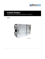
6.0 ROOFTOP UNIT DIMENSIONS
6.1 LE6XRTH-F DIMENSION DRAWING
6.2 LE6XRTV-R DIMENSION DRAWING
Subject to change without notice: RENEWAIRE.COM | 1.800.627.4499 98 Subject to change without notice: RENEWAIRE.COM | 1.800.627.4499
SPECIFICATIONS & DIMENSIONS
2" Duct
Flange Typ.
73 3/8"
Lifting Lugs
19 5/8"
Typ.
22 1/4"
69 1/4" Case
111 1/8" Overall
2" Typ.
FRONT VIEW
Pressure Ports
(4) Typ.
FA
RTR
ONLY
FA
RTV
ONLY
RA
122 5/8" Case
125 3/8" Overall
OA Inlets,
OA Damper
Locations
(Optional)
RIGHT VIEW
53 1/2"
44 5/8"
8 7/8"
25 1/4"
4"
65 5/8" Case
71 1/8" Overall
C
L
11 3/8"
(5)
7/8"
Knockouts
C
L
5 1/4"
(2)
7/8"
Knockouts
Disconnect
Switch
E-Box
EA Outlet
13 3/8" X 15 1/2"
Electrical
Connection
Cover
FA (RTR)
32" X 24"
Duct Receiving
Flange
18 3/8"
49 5/8"
41"
46"
36" E-Box
Minimum
Service Area
111" Minimum
Service Area
60 1/4"
Minimum
Blower Service
Area Typ.
69 3/4" Minimum
Service Area
TOP VIEW
Door
Swing
Door
Swing
Door
Swing
Door
Swing
OA
OA
EA
FA (RTV)
16 1/8" X 19 1/2"
Opening
RA
24" X 32"
Opening
RA Damper
Location
(Optional)
115 1/4" O.D.
64 1/4" O.D.
3"
60 1/2" I.D.
17 1/4"
33"
20" 25"
9 1/2"
A
A
TOP VIEW
CURB LE6X
FA
RA
1 7/8"
3"
14"
SECTION
A-A
CURB CROSS-SECTION
A-A (TYP.)
1 1/2" X 1/4"
Neoprene Gasket
3/4" X 3 1/2"
Wooden Nailer
LEFT VIEW
Model: LE6X RTV/RTR
Drawing Type: Unit Dimension
Version: MAY18
ABBREVIATIONS
EA: Exhaust Air to outside
OA: Outside Air intake
RA: Room Air to be exhausted
FA: Fresh Air to inside
RTV: Rooftop Vertical RA & FA
RTR: Rooftop Vertical RA Only
INSTALLATION ORIENTATION
Unit must be installed in orientation
shown.
NOTE:
1. UNLESS OTHERWISE SPECIFIED,
DIMENSIONS ARE ROUNDED TO THE
NEAREST EIGHTH OF AN INCH.
2. SPECIFICATIONS MAY BE SUBJECT
TO CHANGE WITHOUT NOTICE.
LE6XRT (RTV/RTR) Energy Recovery Ventilator Standard
AIRFLOW ORIENTATION
Available as shown:
UNIT MOUNTING & APPLICATION
Must be mounted as shown. Airstreams can not
be switched.
EA
AR
AF
OA
HERT except 6x 8x, LERT
RTV
AR
FA
EA OA
HERT except 6x 8x, LERT
RTR
Subject to change without notice: RENEWAIRE.COM | 1.800.627.4499 1110 Subject to change without notice: RENEWAIRE.COM | 1.800.627.4499
SPECIFICATIONS & DIMENSIONS
2" Typ.
2" Duct
Flange Typ.
73 3/8"
Lifting Lugs
19 5/8"
Typ.
22 1/4"
69 1/4" Case
111 1/8" Overall
5" Damper
Frames Typ.
FRONT VIEW
Pressure Ports
(4) Typ.
FA
RTH
ONLY
RA
FA
RTF
ONLY
122 5/8" Case
125 3/8" Overall
25 3/8"
8 3/4"
OA Inlets,
OA Damper
Locations
(Optional)
RIGHT VIEW
RA
32" X 24"
Duct Receiving
Flange
RA Damper
Location
(Optional)
53 1/2"
44 5/8"
8 3/4"
25 1/4"
4"
65 5/8" Case
71 1/8" Overall
C
L
5 1/4"
(2)
7/8"
Knockouts
C
L
11 3/8"
(5)
7/8"
Knockouts
Disconnect
Switch
E-Box
EA Outlet
13 3/8" X 15 1/2"
Electrical
Connection
Cover
FA (RTH)
32" X 24"
Duct Receiving
Flange
18 3/8"
46"
36" E-Box
Minimum
Service Area
111" Minimum
Service Area
60 1/4"
Minimum
Blower Service
Area Typ.
69 3/4" Minimum
Service Area
TOP VIEW
Door
Swing
Door
Swing
Door
Swing
Door
Swing
OA
OA
EA
FA ( RTF)
16 1/8" X 19 1/2"
Opening
115 1/4" O.D.
64 1/4" O.D.
3"
60 1/2" I.D.
17 1/4"
33"
20" 25"
9 1/2"
A
A
TOP VIEW
CURB LE6X
FA
RA
1 7/8"
3"
14"
SECTION
A-A
CURB CROSS-SECTION
A-A (TYP.)
1 1/2" X 1/4"
Neoprene Gasket
3/4" X 3 1/2"
Wooden Nailer
LEFT VIEW
Model: LE6X RTH/RTF
Drawing Type: Unit Dimension
Version: MAY18
ABBREVIATIONS
EA: Exhaust Air to outside
OA: Outside Air intake
RA: Room Air to be exhausted
FA: Fresh Air to inside
RTF: Rooftop Vertical FA Only
RTH: Rooftop Horizontal RA & FA
INSTALLATION ORIENTATION
Unit must be installed in orientation
shown.
NOTE:
1. UNLESS OTHERWISE SPECIFIED,
DIMENSIONS ARE ROUNDED TO THE
NEAREST EIGHTH OF AN INCH.
2. SPECIFICATIONS MAY BE SUBJECT
TO CHANGE WITHOUT NOTICE.
LE6XRT (RTH/RTF)
Energy Recovery Ventilator Standard
AIRFLOW ORIENTATION
Available as shown:
UNIT MOUNTING & APPLICATION
Must be mounted as shown. Airstreams can not
be switched.
AF
EA
RA
OA
HERT except 6x 8x, LERT
RTF
RA
EA
FA
OA
HERT except 6x 8x, LERT
RTH
THIS PAGE IS INTENTIONALLY LEFT BLANK.
/