Page is loading ...

MAN 139CMAN 139C
Model ANT 029 Rack Mountable Remote Antenna Model ANT 029 Rack Mountable Remote AntennaModel ANT 029 Rack Mountable Remote Antenna
Overview
The ANT 029 is a 75 Ohm rack mountable remote antenna designed for 72-76 MHz
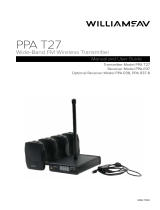
operation. It is intended for use with Williams Sound FM transmitters (i.e. PPA T35,
PPA T27).
Contents
1 - Rack Mount Bracket Assembly
1 - ANT 021 Rubber Duckie Antenna with Swivel F-Connector
1 - WCA 086 Coax Cable, 3’, F-Connector
2 - #10-32 Screws and Nylon Washers
1 - Manual
Recycling Instructions
Help Williams Sound protect the environment! Please take the time to dispose of
your equipment properly.
Product Recycling
Please do NOT dispose of your Williams Sound equipment in the household
trash. Please take the equipment to an electronics recycling center; OR return
the product to the factory for proper disposal.
(2) #10-32 MOUNT SCREWS & WASHERS
FOR RACK INSTALLATION
WCA 086
3’ COAX CABLE
MOUNTING
BRACKET
CONNECTOR
ANT 021
RUBBER DUCKIE
ANTENNA WITH SWIVEL
F-CONNECTOR
TO TRANSMITTER
REMOTE
ANTENNA JACK
A170
Figure 1: ANT 029 Assembly
ANT 029 Assembly & Installation Procedure
1. Select a mounting location for the ANT 029 Remote Antenna. The ANT 029 can
be mounted on an audio rack, wall, corner, or behind a wooden beam. If possible,
avoid placing the antenna within four feet of steel beams. Metal studs, ductwork,
and foil-backed insulation can absorb radio energy, reducing the range of the
system.
2. If installing on wall or other surface, use mounting bracket as a template to mark
position of mounting holes. Use appropriate wall anchors and screws as necessary
(not included).
3. Thread the ANT 021 rubber duckie on to the connector of mounting bracket (see
gure 1). Turn the F-connector on the ANT 021 clockwise by hand until connection
is tight.
4. Thread one end of the WCA 086 3’ coax cable on to the back of the assembled
bracket-antenna unit. Use ngers only to tighten.
5. Use provided #10-32 screws and washers to mount bracket-antenna assembly on
to audio rack; alternatively, use wall anchors and screws (not included) to mount
bracket-antenna assembly on to marked wall/surface area. Make sure bracket-
antenna assembly is secure.
6. Attach other end of WCA 086 3’ coax cable to the F-Connector “Antenna” jack on
the Williams Sound 72-76 MHz transmitter (i.e. PPA T35, T27). Use ngers only to
tighten.
NOTE: Do not bend coax cable sharply at any point. The ANT 021 rubber duckie
antenna should be vertical for best performance, and to comply with
FCC rules.
Warranty
The ANT 029 rack mountable remote antenna is covered by a 90 day warranty. If you
experience difculty with your antenna, call toll-free for customer assistance:
1-800-843-3544 (U.S.A.) or 1-952-943-2252 (Outside the U.S.A.)
If it is necessary to return the system for service, your customer service representative
will give you a Return Authorization Number (RA) and shipping instructions.
/


