A.O. Smith ADM - 50 User manual

Category
Water heaters & boilers
Type
User manual
Instruction manual ADM 3
gis
Read this manual carefully
Warning
Read this manual carefully before starting up the water heater. Failure to
read this manual and to follow the instructions in this manual may lead to
accidents, personal injury, and damage to the appliance.
Copyright © 2008 A.O. Smith Water Products Company
All rights reserved.
Nothing from this publication may be copied, reproduced and/or published by
means of printing, photocopying or by whatsoever means, without the prior
written approval of A.O. Smith Water Products Company.
A.O. Smith Water Products Company reserves the right to modify specifications
stated in this manual.
Trademarks
Any brand names mentioned in this manual are registered trademarks of their
respective owners.
Liability
A.O. Smith Water Products Company accepts no liability for claims from third
parties arising from improper use other than that stated in this manual and in
accordance with the General Conditions registered at the Eindhoven Chamber
of Commerce.
Refer further to the General Conditions. These are available on request, free of
charge.
Although considerable care has been taken to ensure a correct and suitably
comprehensive description of all relevant components, the manual may
nonetheless contain errors and inaccuracies.
Should you detect any errors or inaccuracies in the manual, we would be
grateful if you would inform us. This helps us to further improve our
documentation.
More information
If you have any comments or queries concerning any aspect related to the
appliance, then please do not hesitate to contact:
A.O. Smith Water Products Company
PO Box 70
5500 AB Veldhoven
Netherlands
Telephone: (free) 0870 - AOSMITH
0870 - 267 64 84
General:
+31 40 294 25 00
Fax: +31 40 294 25 39
E-mail : info@aosmith.nl
Website: www.aosmithinternational.com
In the event of problems with connecting to the gas, electricity or water supply,
please contact your installation's supplier/installation engineer .
4 Instruction manual ADM
gis
Instruction manual ADM 5
Table of contents
1 Introduction - - - - - - - - - - - - - - - - - - - - - - - - - - - 7
1.1 About the appliance - - - - - - - - - - - - - - - - - - - - - - - - - - - - 7
1.2 What to do if you smell gas- - - - - - - - - - - - - - - - - - - - - - - - - 7
1.3 Regulations - - - - - - - - - - - - - - - - - - - - - - - - - - - - - - - - 7
1.4 Target groups - - - - - - - - - - - - - - - - - - - - - - - - - - - - - - - 8
1.5 Maintenance - - - - - - - - - - - - - - - - - - - - - - - - - - - - - - - - 8
1.6 Forms of notation - - - - - - - - - - - - - - - - - - - - - - - - - - - - - 8
1.7 Overview of this document - - - - - - - - - - - - - - - - - - - - - - - - - 9
2 Working principle of the appliance- - - - - - - - - - - - - - - 11
2.1 Introduction - - - - - - - - - - - - - - - - - - - - - - - - - - - - - - - 11
2.2 General working principle of the appliance - - - - - - - - - - - - - - - - 11
2.3 The appliance's heating cycle - - - - - - - - - - - - - - - - - - - - - - 12
2.4 Protection for the appliance - - - - - - - - - - - - - - - - - - - - - - - 12
2.5 Safety of the installation - - - - - - - - - - - - - - - - - - - - - - - - - 13
3 Installation - - - - - - - - - - - - - - - - - - - - - - - - - - - 15
3.1 Introduction - - - - - - - - - - - - - - - - - - - - - - - - - - - - - - - 15
3.2 Packaging - - - - - - - - - - - - - - - - - - - - - - - - - - - - - - - - 15
3.3 Ambient conditions- - - - - - - - - - - - - - - - - - - - - - - - - - - - 15
3.4 Technical specifications - - - - - - - - - - - - - - - - - - - - - - - - - 17
3.5 Installation diagram - - - - - - - - - - - - - - - - - - - - - - - - - - - 21
3.6 Water connections, Vented- - - - - - - - - - - - - - - - - - - - - - - - 22
3.7 Water connections, Unvented - - - - - - - - - - - - - - - - - - - - - - 23
3.8 Gas connection - - - - - - - - - - - - - - - - - - - - - - - - - - - - - 24
3.9 Chimney flue- - - - - - - - - - - - - - - - - - - - - - - - - - - - - - - 25
3.10 Electrical connection - - - - - - - - - - - - - - - - - - - - - - - - - - - 26
3.11 Checking the supply pressure and burner pressure - - - - - - - - - - - - 28
4 Conversion to a different gas category - - - - - - - - - - - - 33
4.1 Conversion to different category ADM 40 through 115 - - - - - - - - - - 34
4.2 Conversion to a different gas category ADM 135 - - - - - - - - - - - - - 36
5 Filling - - - - - - - - - - - - - - - - - - - - - - - - - - - - - - 41
5.1 Filling unvented installations - - - - - - - - - - - - - - - - - - - - - - - 42
5.2 Filling vented installations - - - - - - - - - - - - - - - - - - - - - - - - 42
6 Draining - - - - - - - - - - - - - - - - - - - - - - - - - - - - 43
6.1 Draining unvented installations - - - - - - - - - - - - - - - - - - - - - - 44
6.2 Draining vented installations - - - - - - - - - - - - - - - - - - - - - - - 45
7 The control panel- - - - - - - - - - - - - - - - - - - - - - - - 47
7.1 Introduction - - - - - - - - - - - - - - - - - - - - - - - - - - - - - - - 47
7.2 Control panel - - - - - - - - - - - - - - - - - - - - - - - - - - - - - - 47
7.3 Explanation of icons - - - - - - - - - - - - - - - - - - - - - - - - - - - 47
7.4 ON/OFF switch - - - - - - - - - - - - - - - - - - - - - - - - - - - - - 47
7.5 Control thermostat - - - - - - - - - - - - - - - - - - - - - - - - - - - - 47
7.6 Burner control reset button - - - - - - - - - - - - - - - - - - - - - - - - 48
7.7 Flue gas thermostat reset button - - - - - - - - - - - - - - - - - - - - - 48
gis
Table of contents
6 Instruction manual ADM
8 Status of the appliance - - - - - - - - - - - - - - - - - - - - - 49
8.1 Introduction - - - - - - - - - - - - - - - - - - - - - - - - - - - - - - - - 49
8.2 Operating modes - - - - - - - - - - - - - - - - - - - - - - - - - - - - - 49
8.3 Error conditions - - - - - - - - - - - - - - - - - - - - - - - - - - - - - - 49
9 Starting and running - - - - - - - - - - - - - - - - - - - - - - 51
9.1 Introduction - - - - - - - - - - - - - - - - - - - - - - - - - - - - - - - - 51
9.2 Starting the appliance - - - - - - - - - - - - - - - - - - - - - - - - - - - 51
9.3 The appliance's heating cycle - - - - - - - - - - - - - - - - - - - - - - - 51
10 Shutting down - - - - - - - - - - - - - - - - - - - - - - - - - 53
10.1 Introduction - - - - - - - - - - - - - - - - - - - - - - - - - - - - - - - - 53
10.2 Shutting down the appliance for a brief period (OFF mode)- - - - - - - - - 53
10.3 Isolating the appliance from the mains - - - - - - - - - - - - - - - - - - - 53
10.4 Shutting the appliance down for a long period - - - - - - - - - - - - - - - 53
11 Troubleshooting - - - - - - - - - - - - - - - - - - - - - - - - 55
11.1 Introduction - - - - - - - - - - - - - - - - - - - - - - - - - - - - - - - - 55
11.2 Error conditions - - - - - - - - - - - - - - - - - - - - - - - - - - - - - - 55
11.3 Troubleshooting table for general errors - - - - - - - - - - - - - - - - - - 56
11.4 ADM Troubleshooting table - no hot water - - - - - - - - - - - - - - - - - 57
11.5 Troubleshooting table - 'insufficient hot water' - - - - - - - - - - - - - - - 59
12 Performing maintenance - - - - - - - - - - - - - - - - - - - - 61
12.1 Introduction - - - - - - - - - - - - - - - - - - - - - - - - - - - - - - - - 61
12.2 Preparation for maintenance - - - - - - - - - - - - - - - - - - - - - - - 61
12.3 Water-side maintenance - - - - - - - - - - - - - - - - - - - - - - - - - 62
12.4 Gas-side maintenance - - - - - - - - - - - - - - - - - - - - - - - - - - 63
12.5 Finalising maintenance - - - - - - - - - - - - - - - - - - - - - - - - - - 64
13 Warranty (certificate) - - - - - - - - - - - - - - - - - - - - - - 65
13.1 General warranty - - - - - - - - - - - - - - - - - - - - - - - - - - - - - 65
13.2 Tank warranty- - - - - - - - - - - - - - - - - - - - - - - - - - - - - - - 65
13.3 Conditions for Installation and use - - - - - - - - - - - - - - - - - - - - - 65
13.4 Exclusions - - - - - - - - - - - - - - - - - - - - - - - - - - - - - - - - 66
13.5 Scope of the warranty - - - - - - - - - - - - - - - - - - - - - - - - - - - 66
13.6 Claims - - - - - - - - - - - - - - - - - - - - - - - - - - - - - - - - - - 66
13.7 Obligations of A.O. Smith - - - - - - - - - - - - - - - - - - - - - - - - - 66
14 Appendices - - - - - - - - - - - - - - - - - - - - - - - - - - - 67
14.1 Introduction - - - - - - - - - - - - - - - - - - - - - - - - - - - - - - - - 67
14.2 Electrical Diagrams ADM - - - - - - - - - - - - - - - - - - - - - - - - - 68
Instruction manual ADM 7
gis
1 Introduction
1.1 About the appliance
This manual describes how to install, service and use the ADM appliance. The
ADM appliance is a gas-fired open boiler without fan. ADM appliances are
equipped with a flue gas backflow safeguard.
The ADM is an appliance of type B
11BS
.
The information in this manual applies to types: ADM 40, ADM 50, ADM 60,
ADM 80, ADM 90, ADM 115 and ADM 135.
The appliance has been manufactured and equipped in accordance with the
European standard for gas-fired storage water heaters for the production of
domestic hot water (EN 89). The appliances are therefore compliant with the
European Directive for Gas Appliances, and and are entitled to bear the CE
mark.
Warning
Read this manual carefully before starting up the water heater. Failure to
read the manual and to follow the printed instructions may lead to personal
injury and damage to the appliance.
1.2 What to do if you
smell gas
Warning
If there is a gas smell:
No naked flames! No smoking!
Avoid causing sparks! Do not use any electrical equipment or switch, i.e. no
telephones, plugs or bells!
Open windows and doors!
Shut off the mains gas supply valve!
Warn occupants and leave the building!
After leaving the building, alert the gas distribution company or your installation
engineer.
1.3 Regulations
As the (end) user, installation engineer or service and maintenance engineer,
you must ensure that the entire installation complies, as a minimum, with the
official local:
building regulations;
energy supplier's directives for existing gas installations;
directives and technical guidelines for natural gas installations;
safety requirements for low-voltage installations;
regulations governing the supply of drinking water;
regulations governing ventilation in buildings;
regulations governing the supply of air for combustion;
regulations governing the discharge of products of combustion;
requirements for installations that consume gas;
regulations governing indoor waste water disposal;
regulations imposed by fire brigade, power companies and municipality.
0063
Introduction
8 Instruction manual ADM
1
gis
Furthermore, the installation must comply with the manufacturer's instructions.
Note
Later amendments and/or additions to all regulations, requirements and
guidelines published on or prior to the moment of installing, will apply to the
installation.
1.4 Target groups
The three target groups for this manual are:
(end) users;
installation engineers;
service and maintenance engineers.
Symbols on each page indicate the target groups for whom the information is
intended. See the table.
Target group symbols
1.5 Maintenance
A service should be carried out at least once a year, both on the water side and
on the gas side. Maintenance frequency depends, among other things, on the
water quality, the average burning time per day and the set water temperature.
Note
To determine the correct maintenance frequency, it is recommended to
arrange for the service and maintenance engineer to check the appliance on
both the water and gas side within three months following installation. Based on
this check, the best maintenance frequency can be determined.
Note
Regular maintenance extends the service life of the appliance.
Note
Both the end user and the service and maintenance engineer are
responsible for regular maintenance. They will need to establish clear
agreements on this.
Note
If the appliance is not regularly maintained, the warranty will become void.
1.6 Forms of notation
The following notation is used in this manual:
Note
Important information.
Caution
Ignoring this information can lead to the appliance being damaged.
Warning
Failure to carefully read this information may lead to personal injury and
serious damage to the appliance.
Symbol Target group
(End) user
Installation engineer
Service and maintenance engineer
Instruction manual ADM 9
gis
1.7 Overview of this
document
The table provides an overview of the contents of this document.
Contents of this document
Chapter Target groups Description
Working principle of the
appliance
This chapter describes how the appliance functions.
Installation This chapter describes the installation activity to be
completed before you actually start up the appliance.
Filling This chapter describes how to fill the appliance.
Draining This chapter describes how to drain the appliance.
The control panel This chapter describes the general operation of the
appliance and explains how to use the control panel.
Status of the appliance This chapter describes the status (mode or condition) that
the appliance may have, and possible actions to take.
Starting and running This chapter describes how to start the appliance running.
The general heating cycle of the appliance is also
described.
Shutting down This chapter describes how to shut the appliance down for
a brief or long period of time.
Troubleshooting This chapter is mainly intended for the installation
engineer and the service and maintenance engineer. It
describes appliance errors. A table is included stating
potential symptoms, causes and solutions. End users
may also refer to this chapter for additional information
about the appliance.
Performing maintenance This chapter sets out the maintenance tasks to be carried
out during a service.
Warranty (certificate) This chapter states the warranty terms and conditions.
Introduction
10 Instruction manual ADM
1
gis
Instruction manual ADM 11
gis
2 Working principle of
the appliance
2.1 Introduction
Topics covered in this chapter:
General working principle of the appliance;
The appliance's heating cycle;
Protection for the appliance;
Safety of the installation.
2.2 General working
principle of the
appliance
The figure shows a cut-away view of the appliance.
Cut-away view of the appliance
Legend
Only applicable numbers are
mentioned.
2. hot water outlet
6. control panel
8. combustion chamber
9. anode
10. tank
11. heat exchanger
12. inspection and cleaning opening
14. cold water inlet
15. drain valve
16. gas control
20. spark igniter
21. flame probe
22. chimney pipe
24. insulation layer
33. draught diverter
34. flue gas sensor
35. radiation shield/condensation
tray
36. bar burners/burner tray
37. flue gas thermostat
38. safety thermostat sensor
39. high-limit thermostat sensor
40. burner control
41. control thermostat
42. high-limit thermostat
43. safety thermostat
44. frost thermostat
45. control thermostat sensor
46. frost thermostat sensor
22
39
46
2
40
38
45
6
41
42
43
44
20
21
14
36
11
33
9
37
34
24
10
12
8
15
35
16
IMD-0133 R2
Working principle of the appliance
12 Instruction manual ADM
2
gis
In this appliance, the cold water enters the bottom of the tank through the cold
water inlet (14). The heat of combustion is conducted to the water by the
combustion chamber (8) and heat exchanger (11). The heated tap water leaves
the tank through the hot water outlet (2). Once the appliance is completely filled
with water, it will constantly be under mains water pressure. When hot water is
drawn from the appliance, it is immediately replenished with cold water.
The gas required for combustion flows via the gas control (16) into the manifold.
Orifices are mounted in the manifold. The gas is injected into the burner bars at
pressure from these orifices (36). The burner bars together form the burner tray.
The injection of gas into the burner bars also draws in the primary air required
for combustion. The narrow opening in the orifice causes the gas flow to
accelerate. This in turn causes a partial vacuum. It is this partial vacuum that
draws in the air (the Venturi effect). Additional air is drawn in through the
opening in the burner tray.
The hot surface igniter (20) ensures ignition of the gas/air mixture.
The flue gases released by this combustion are led through the flue tubes (part
of 11). Flue baffles (part of 11) are mounted in the flue tubes. These retard the
flow of the flue gases, thereby increasing the thermal efficiency of the appliance.
The flue gases are vented from the appliance via the draught diverter (33).
A radiation shield/condensation tray (35) is mounted below the burner tray. This
prevents overheating of the floor area below the appliance, as well as serving
as a collection tray for condensation water.
The insulation layer (24) prevents heat loss. The inside of the tank is enamelled
to protect against corrosion. The anodes (9) offer extra protection.
2.3 The appliance's
heating cycle
The entire appliance is controlled by the burner control (40) and the control
thermostat (41) or frost thermostat (44). The control thermostat and frost
thermostat both independently measure the water temperature (T
water
). The
appliance's heating cycle is activated as soon as T
water
falls below the threshold
value (T
set
). The value of T
set
depends on the selected mode of the
appliance (8.2 "Operating modes"). When the appliance is in OFF mode (frost
protection), this value is determined by the frost thermostat (threshold value =
20°C). When the appliance is in ’ON mode’, the threshold value can be set via
the control thermostat (±40°C - ±70°C).
As soon as T
water
falls below T
set
, the relevant thermostat (control or frost) will
close, and the burner control will register demand. The gas control (16) is
opened, and the gas is mixed with air. This mixture is ignited by the hot surface
igniter (20) and the water is heated. As soon as T
water
gets higher than T
set
, the
thermostat opens again. The demand will cease, and the burner control will stop
the heating cycle.
The thermostats have a certain margin both when closing and opening. We refer
to this margin as the hysteresis. The hysteresis cannot be adjusted.
2.4 Protection for the
appliance
2.4.1 Introduction
The burner control monitors the water temperature by means of thermostats
and ensures safe combustion. This takes place using:
the Water temperature protection;
the Flue gas backflow safeguard;
the Flame probe.
Instruction manual ADM 13
gis
2.4.2 Water temperature protection
By means of the frost, high-limit and safety thermostats, the burner control
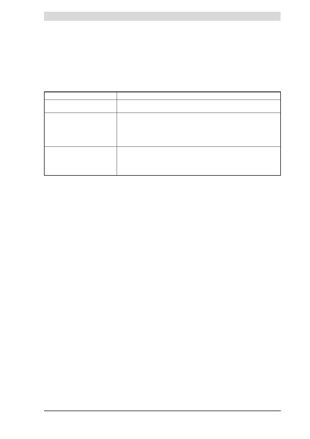
monitors three temperatures that are important for safety. The table explains the
working principle of the thermostats with sensors.
Temperature protection
2.4.3 Flue gas backflow safeguard
The flue gases are discharged to the outside via the draught diverter (33) and
the flue (22). To prevent the flue gases from flowing back into the boiler room,
the discharge ducting is monitored by a feature called the Thermal Reflux
Safeguard (TRS). This uses a flue gas thermostat (37) with a flue gas
thermostat sensor (34) that are located in the draught diverter. Under normal
circumstances this sensor will register the ambient temperature.
However, if the chimney is not drawing sufficiently (for example, due to a
blockage in the chimney), the flue gases will 'reflux' and flow back past the flue
gas thermostat sensor. The sensor will then detect an excessive temperature
and the flue gas thermostat will open. The demand will cease, and the burner
control will immediately stop the heating cycle. The flue gas thermostat will also
lock out. It must be manually reset before the appliance can resume operation .
2.4.4 Flame probe
To ensure that no gas can flow when there is no combustion, the water heater
is fitted with a flame probe (21). The burner control uses the ionisation-detecting
properties of this probe for flame detection. The burner control closes the gas
valve the instant it determines that there is a gas flow but no flame is present.
2.5 Safety of the
installation
In addition to the appliance's standard built-in safety monitoring, the appliance
must also be protected by an expansion vessel, expansion valve, pressure
reducing valve, non-return valve and a T&P valve.
The use of an expansion vessel, expansion valve and/or pressure reducing
valve depends on the type of installation: unvented or vented.
2.5.1 Inlet combination and pressure-reducing valve
In addition to the appliance's standard built-in safety monitoring, the appliance
must also be protected by an expansion vessel, expansion valve, pressure
reducing valve, non-return valve and a T&P valve.
The use of an expansion vessel, expansion valve and/or pressure reducing
valve depends on the type of installation: unvented or vented.
Protection Description
Frost thermostat When the frost thermostat sensor (46) measures a temperature of 20°C or
less, the heating cycle (2.3 "The appliance's heating cycle") will start.
High-limit thermostat When the high-limit thermostat sensor (39) measures a temperature higher
than 84°C, the high-limit thermostat will open. The heat demand is terminated
and the burner control halts the heating cycle until the high-limit thermostats
close once more. At that moment the burner control will reset the appliance and
the heating cycle will restart. The high-limit safeguard serves to prevent
overheating and/or excessive formation of scale in the appliance.
Safety thermostat When the safety thermostat sensor (38) measures a temperature higher than
93°C, the safety thermostat will open. The heat demand is terminated and the
burner control will immediately halt the heating cycle. The burner control will go
into a lockout error state. This must be manually reset before the appliance can
resume operation.
Working principle of the appliance
14 Instruction manual ADM
2
gis
2.5.2 Unvented installation
With an unvented installation, an expansion valve valve and expansion vessel
prevent the buildup of excessive pressure in the tank. This prevents damage
being caused to the enamelled coating (in the appliance) or to the tank. A non-
return valve prevents excessive pressure buildup in the water supply system.
This valve also prevents water from flowing backwards from the tank into the
cold water supply system. The pressure reducing valve protects the installation
against an excessively high water supply pressure (> 8 bar). These components
are fitted to the cold water pipe (3.6 "Water connections, Vented").
2.5.3 Vented installation
With vented installation, excess pressure is taken up by the open cold water
head tank. The head height of the tank determines the working pressure in the
water heater, which may not exceed 8 bar. The installation must also be fitted
with a vent pipe from the hot water pipe (3.6.3 "Hot water side"), which opens
into the cold water tank.
2.5.4 T&P valve
A T&P valve is only mandatory in an unvented installation. However, A.O. Smith
also recommends the use of a T&P valve in vented installations.
A T&P (Temperature and Pressure Relief) valve monitors the pressure in the
tank and the water temperature at the top of the tank. If the pressure in the tank
becomes excessive (> 10 bar) or the water temperature is too high (> 97°C), the
valve will open. The hot water can now flow out of the tank. Because the
appliance is under water supply pressure, cold water will automatically flow into
the tank. The valve remains open until the unsafe situation has been rectified.
The appliance is fitted standard with a connecting point for a T&P
valve (3.7.3 "Hot water side").
Instruction manual ADM 15
is
3 Installation
Warning
Installation work should be carried out by an approved installation engineer
in compliance with the general and local regulations imposed by the gas, water
and power supply companies and the fire service.
The appliance may only be installed in a room that complies with the
requirements stated in national and local ventilation
regulations (1.3 "Regulations").
3.1 Introduction
This chapter describes the installation activities to be carried out before the
appliance may be started up (9 "Starting and running"), in particular:
Packaging;
Ambient conditions;
Technical specifications;
Water connections, Vented;
Gas connection;
Chimney flue;
Electrical connection;
Checking the supply pressure and burner pressure.
For a possible conversion to a different gas category, see
conversion (4 "Conversion to a different gas category").
3.2 Packaging
To avoid damaging the appliance, remove the packaging carefully.
We recommend unpacking the appliance at or near its intended location.
Caution
The appliance may only be manoeuvred in an upright position. Take care
that the appliance is not damaged after unpacking.
3.3 Ambient conditions
Caution
The appliance may not be used in rooms where chemical substances are
stored or used, due to the risk of explosion and/or corrosion of the appliance.
Some propellants, bleaching agents, degreasing agents etc. disperse vapours
which are explosive and/or which cause accelerated corrosion. If the appliance
is used in a room in which such substances are present, the warranty will be
void.
ADM appliances are open appliances and may only be installed in an open
boiler room. Their type is B
11BS
.
3.3.1 Air humidity and ambient temperature
The boiler room must be frost-free, or be protected against frost. The table
shows the environmental conditions that must be adhered to for correct
functioning of the electronics present in the appliance to be guaranteed.
Installation
16 Instruction manual ADM
3
is
Air humidity and ambient temperature specifications
3.3.2 Maximum floor load
In connection with the appliance's weight, take account of the maximum floor
loading, refer to the table.
3.3.3 Water composition
The appliance is intended for heating drinking water. The drinking water must
comply with the regulations governing drinking water for human consumption.
The table gives an overview of the specifications.
Water specifications
Note
If the water specifications deviate from those stated in the table, then the
tank protection cannot be guaranteed (13 "Warranty (certificate)").
3.3.4 Working clearances
For access to the appliance, it is recommended that the following clearances
are observed (see figure):
AA: around the appliance's control column and cleaning openings: 100 cm.
BB: all sides of the appliance: 50 cm.
Above the appliance (room to replace the anodes):
- 100 cm if using fixed anodes, or
- 50 cm if using flexible anodes.
If the available clearance is less than 100 cm, flexible magnesium anodes
may be ordered.
Note
When installing the appliance, be aware that any leakage from the tank
and/or connections can cause damage to the immediate environment or floors
below the level of the boiler room. If this is the case, the appliance should be
installed above a wastewater drain or in a suitable metal leak tray.
The leak tray must have an appropriate wastewater drain and must be at least
5cm deep with a length and width at least 5cm greater than the diameter of the
appliance.
Air humidity and ambient temperature
Air humidity max. 93% RV at +25°C
Ambient temperature Functional: 0 <
T < 60°C
Weight of the appliance filled with water
ADM 40 ADM 50 ADM 60 ADM 80 ADM 90 ADM 115 ADM 135
504 kg 578 kg 507 kg 573 kg 522 kg 523 kg 581 kg
Water composition
Hardness
(alkaline earth ions)
> 1.00 mmol/l:
German hardness> 5.6° dH
French hardness > 10.0° fH
English hardness > 7.0° eH
Conductivity > 125 µS/cm
Acidity (pH value) 7.0 < pH value < 9.5
Instruction manual ADM 17
is
Working clearances
3.4 Technical
specifications
The appliance is supplied without accessories. Check the
dimensions (3.4.1 "Dimensions of the appliance"), gas data (3.4.3 "Gas data")
and other specifications (3.4.2 "General and electrical specifications") of any
accessories you plan to use.
B
B
A
A
A
A
A
A
IMD-0262 R2
Installation
18 Instruction manual ADM
3
is
3.4.1 Dimensions of the appliance
Plan and elevation of the appliance
Legend
See the table.
10º
37º 45º
F
E
A
D
H
G
B
M
R
K
P
S
N
J
6
1
3
4
6
2
5
IMD-
0
1
35
R2
Instruction manual ADM 19
is
Dimensions (all measurements in mm unless otherwise indicated)
3.4.2 General and electrical specifications
General and electrical specifications
Dime
nsion
Description ADM
40
ADM
50
ADM
60
ADM
80
ADM
90
ADM
115
ADM
135
A Total height 1900 2100 1900 2100 2000 2085 2085
B Height of top of appliance 1760 1960 1760 1960 1795 1870 1870
D Appliance diameter 710 710 710 710 710 710 710
E Depth 800 800 800 800 800 800 800
F Width 1100 1100 1100 1100 1105 1105 1105
G Diameter of chimney flue 150 150 180 180 225 225 225
H Heart appliance / Heart chimney
flue
660 660 660 660 675 675 675
J Height of chimney flue 1840 2040 1840 2040 1935 2010 2010
K Height of gas connection 400 400 400 400 400 400 205
M Height of cold water supply 565 565 565 565 575 650 650
N Height of hot water outlet 1605 1810 1605 1810 1640 1715 1715
P Height of cleaning opening 730 730 730 730 740 825 855
R Height of drain valve connection 500 515 500 515 525 600 595
S Height of T&P valve connection 1550 1760 1550 1760 1595 1660 1660
1 Cold water supply connection
(male)
R1
1
/
2
R1
1
/
2
R1
1
/
2
R1
1
/
2
R1
1
/
2
R1
1
/
2
R1
1
/
2
2 Hot water outlet connection
(female)
Rp1
1
/
2
Rp1
1
/
2
Rp1
1
/
2
Rp1
1
/
2
Rp1
1
/
2
Rp1
1
/
2
Rp1
1
/
2
3 Gas control connection (female) Rp
3
/
4
Rp
3
/
4
Rp
3
/
4
Rp
3
/
4
Rp
3
/
4
Rp
3
/
4
Rp1
4 Drain valve connection (female) Rp1
1
/
2
Rp1
1
/
2
Rp1
1
/
2
Rp1
1
/
2
Rp1
1
/
2
Rp1
1
/
2
Rp1
1
/
2
5 T&P valve connection (female) 1 - 11.5
NPT
1 - 11.5
NPT
1 - 11.5
NPT
1 - 11.5
NPT
Rp1
1
/
2
Rp1
1
/
2
Rp1
1
/
2
6 Cleaning/inspection opening Ø 100 Ø 100 Ø 100 Ø 100 Ø 100 Ø 100 Ø 100
DESCRIPTION Unit ADM
40
ADM
50
ADM
60
ADM
80
ADM
90
ADM
115
ADM
135
Capacity litres 309 357 298 335 278 253 252
Maximum operating pressure bar 8 8 8 8 8 8 8
Empty weight kg 195 221 209 238 244 270 329
Heating-up time T=45
o
C minutes 30 26 19 17 12 8 7
Number of anodes - 2 2 2 3 3 4 4
Number of bar
burners/orifices
- 3457796
Number of flue tubes/flue
baffles
-5679121617
Electrical power consumption W 30 30 30 30 30 30 60
Supply voltage
(-15% +10% VAC)
volts 230 230 230 230 230 230 230
Mains frequency Hz (± 1Hz) 50 50 50 50 50 50 50
IP class - 30 30 30 30 30 30 30
Installation
20 Instruction manual ADM
3
is
3.4.3 Gas data
Gas data
Description II
2H3+
Unit ADM
40
ADM
50
ADM
60
ADM
80
ADM
90
ADM
115
ADM
135
Gas category 2H: General
Orifice diameter mm 3.20 3.20 3.10 2.95 3.20 3.20 3.90
(1) = Blank plate
(2) = Burner pressure regulator
(3) = High/low regulator
1, 2 or 32222222
Gas category G20 - 20 mbar
Nominal load (gross calorific value) kW 42.2 56.5 66.4 82.5 98.3 126.6 143.4
Nominal output kW 32.3 42.8 50.2 62.4 74.3 95.8 109.8
Supply pressure mbar 20 20 20 20 20 20 20
Burner pressure mbar 8.5 8.5 8.5 8.5 8.5 8.5 11.3
Gas consumption
(*)
m
3
/h 4.0 5.4 6.3 7.9 9.4 12.1 13.7
Gas category 3+: General
Orifice diameter mm 1.70 1.70 1.70 1.50 1.70 1.70 2.25
(1) = Blank plate
(2) = Burner pressure regulator
(3) = High-low control
1, 2 or 31111113
Gas category G30 - 30 mbar
Nominal load (gross calorific value) kW 41.6 55.3 68.2 80.7 96.1 123.5 138.4
Nominal output kW 32.6 42.8 52.8 62.6 74.5 95.8 108.5
Supply pressure mbar 30 30 30 30 30 30 30
Burner pressure
(†)
mbar-------
Gas consumption
(*)
kg/h 3.0 4.0 5.0 5.9 7.0 9.0 10.1
Gas category G31 - 37 mbar
Nominal load (gross calorific value) kW 38.4 51.1 63.3 77.7 89.6 113.0 130.1
Nominal output kW 30.0 39.5 48.9 60.1 69.2 87.4 101.7
Supply pressure mbar 37 37 37 37 37 37 37
Burner pressure
(†)
mbar-------
Gas consumption
(*)
kg/h 2.7 3.7 4.5 5.6 6.4 8.1 9.3
(*) Based on 1013.25 mbar and 15 °C.
(†) If using a blank plate instead of a burner pressure regulator, it is assumed that the burner pressure is equal to
the supply pressure. In practice, however, the burner pressure will be lower.
  • Page 1 1
  • Page 2 2
  • Page 3 3
  • Page 4 4
  • Page 5 5
  • Page 6 6
  • Page 7 7
  • Page 8 8
  • Page 9 9
  • Page 10 10
  • Page 11 11
  • Page 12 12
  • Page 13 13
  • Page 14 14
  • Page 15 15
  • Page 16 16
  • Page 17 17
  • Page 18 18
  • Page 19 19
  • Page 20 20
  • Page 21 21
  • Page 22 22
  • Page 23 23
  • Page 24 24
  • Page 25 25
  • Page 26 26
  • Page 27 27
  • Page 28 28
  • Page 29 29
  • Page 30 30
  • Page 31 31
  • Page 32 32
  • Page 33 33
  • Page 34 34
  • Page 35 35
  • Page 36 36
  • Page 37 37
  • Page 38 38
  • Page 39 39
  • Page 40 40
  • Page 41 41
  • Page 42 42
  • Page 43 43
  • Page 44 44
  • Page 45 45
  • Page 46 46
  • Page 47 47
  • Page 48 48
  • Page 49 49
  • Page 50 50
  • Page 51 51
  • Page 52 52
  • Page 53 53
  • Page 54 54
  • Page 55 55
  • Page 56 56
  • Page 57 57
  • Page 58 58
  • Page 59 59
  • Page 60 60
  • Page 61 61
  • Page 62 62
  • Page 63 63
  • Page 64 64
  • Page 65 65
  • Page 66 66
  • Page 67 67
  • Page 68 68
  • Page 69 69
  • Page 70 70
  • Page 71 71
  • Page 72 72
  • Page 73 73
  • Page 74 74

A.O. Smith ADM - 50 User manual

Category
Water heaters & boilers
Type
User manual

Ask a question and I''ll find the answer in the document

Finding information in a document is now easier with AI