Transition Networks CSDTF1013-100 User manual

Category
Network media converters
Type
User manual

This manual is also suitable for

COMPLIANCE INFORMATION
UL Listed
C-UL Listed (Canada)
CISPR22/EN55022 Class A + EN55024
CE Mark
FCC Regulations
This equipment has been tested and found to comply with the limits for a class A digital device, pursuant
to part 15 of the FCC rules. These limits are designed to provide reasonable protection against harmful
interference when the equipment is operated in a commercial environment. This equipment generates,
uses, and can radiate radio frequency energy and, if not installed and used in accordance with the
instruction manual, may cause harmful interference to radio communications. Operation of this
equipment in a residential area is likely to cause harmful interference, in which case the user will be
required to correct the interference at the user’s own expense.
Canadian Regulations
This digital apparatus does not exceed the Class A limits for radio noise for digital apparatus set out on
the radio interference regulations of the Canadian Department of Communications.
Le présent appareil numérique n'émet pas de bruits radioélectriques dépassant les limites applicables
aux appareils numériques de la class A prescrites dans le Règlement sur le brouillage radioélectrique
édicté par le ministère des Communications du Canada.
European Regulations
Warning
This is a Class A product. In a domestic environment this product may cause radio interference in which
case the user may be required to take adequate measures.
Achtung !
Dieses ist ein Gerät der Funkstörgrenzwertklasse A. In Wohnbereichen können bei Betrieb dieses Gerätes
Rundfunkstörungen auftreten, in weichen Fällen der Benutzer für entsprechende Gegenmaßnahmen
werantwortlich ist.
Attention !
Ceci est un produit de Classe A. Dans un environment domestique, ce produit risque de créer des
interférences radioélectriques, il appartiendra alors à l’utilsateur de prende les measures spécifiques
appropriées
Trademark Notice
All registered trademarks and trademarks are the property of their respective owners.
Copyright Restrictions
© 2001, 2002 TRANSITION Networks.
All rights reserved. No part of this work may be reproduced or used in any form or by any means –
graphic, electronic, or mechanical – without written permission from TRANSITION Networks.
Printed in the U.S.A. 33201.C
CAUTION: RJ connectors are NOT INTENDED FOR CONNECTION TO THE
PUBLIC TELEPHONE NETWORK. Failure to observe this caution could result in
damage to the public telephone network.
Der Anschluss dieses Gerätes an ein öffentlickes Telekommunikationsnetz in den EG-Mitgliedstaaten
verstösst gegen die jeweligen einzelstaatlichen Gesetze zur Anwendung der Richtlinie 91/263/EWG zur
Angleichung der Rechtsvorschriften der Mitgliedstaaten über Telekommunikationsendeinrichtungen
einschliesslich der gegenseitigen Anerkennung ihrer Konformität.
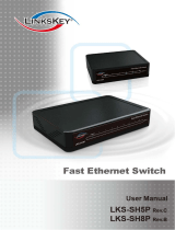
TRANSITION Networks CSDTF10xx-100 series media converters, designed to be
installed in a PointSystem
Conversion Center
chassis, encode and decode T1 or
E1 twisted-pair copper signals over duplex fiber-optic cable to extend the distance
and transmission reliability of high speed T1 or E1 data traffic.
*In CSDTF10xx model designation, 10
represents the T1 or E1 RJ-45 connector;
xx represents the selectable fiber connector
installed on the media converter.
T1/E1 Twisted-Pair Copper
to Fiber
Slide-In-Module Media Converters
CSDTF10xx*-100
USER’S GUIDE
CSDTF1011-100
Provides an RJ-45 twisted pair copper
connector for T1 or E1 signals and a set
of RX/TX ST connectors to 850 nm
multimode duplex fiber-optic cable.
CSDTF1012-100
Provides an RJ-45 twisted pair copper
connector for T1 or E1 signals and an
RX/TX ST connector to 1300 nm
singlemode duplex fiber-optic cable.
CSDTF1013-100
Provides an RJ-45 twisted pair copper
connector for T1 or E1 signals and an
RX/TX SC connector to 850 nm
multimode duplex fiber-optic cable.
CSDTF1014-100
Provides an RJ-45 twisted pair copper
connector for T1 or E1 signals and an
RX/TX SC-SM connector to 1300 nm
singlemode duplex fiber-optic cable.
CSDTF1015-100 (long haul)
Provides an RJ-45 twisted pair copper
connector for T1 or E1 signals and an
RX/TX SC-LH connector to 1300 nm
singlemode duplex fiber-optic cable.
CSDTF1022-100 (long haul)
Provides an RJ-45 twisted pair copper
connector for T1 or E1 signals and an
RX/TX ST connector to 1300 nm
singlemode duplex fiber-optic cable.
CSDTF10xx in the Network . . . . . . .2
Installation . . . . . . . . . . . . . . . . . . . .3
Operation . . . . . . . . . . . . . . . . . . . . .7
Fault Isolation and Correction . . . . .8
Cable Specifications . . . . . . . . . . . .10
Technical Specifications . . . . . . . . .11
Compliance Information . . . . . . . . .12
SET
DB-9
CF
M
10BASE-2
CECF100
0
50‰
CFMFF100
CSDTF100
Link Alert
E
D
CFETF110
CFMFF100
CFMFF100
LKS
PWR
LKM
LKS
PWR
LKM
Multimode
Singlemode
TX
RX
TX
RX
RXF
RXC
LKC
LA
PWR
RXF
RXC
LNK
COL
RX
TX
RX
TX
CFETF100
RX
TX
50‰
Multimode
Singlemode
TX
RX
TX
RX
LKS
PWR
LKM
10BASE-T
LKS
LKM
Multimode
Singlemode
TX
RX
TX
RX
Multimode
Singlemode
TX
RX
TX
RX
PWR
SDF
SDC
LOOP
PWR
SDF
SDC
LOOP
PWR
SDF
SDC
LOOP
CSDTF10xx IN THE NETWORK
NOTE: THE CSDTF10xx REQUIRES A CSU BETWEEN THE MEDIA
CONVERTER AND THE PUBLIC TELEPHONE NETWORK.
NOTE: T1/E1 MEDIA CONVERTERS MUST BE USED IN PAIRS. A TRANSITION
Networks CSDTF10xx chassis media converter can be used with another
CSDTF10xx chassis media converter, a SSDTF10xx stand-alone media
converter, or with a previous model TRANSITION Networks T1/E1 media
converter, such as a C/T1E1-CF-01 or a T1E1-CF-01.
Features
Media converter is framing independent (as ESF vs D4) and supports all
common line codes, (AMI, B8ZS, HDB3).
Dry relay contacts allow media converter to be tied into separate alarm
circuit
All Ones Insertion (AIS) on loss of signal at copper and/or fiber interface.
TECHNICAL SPECIFICATIONS
Standards Emissions: CISPR A
T1/E1 Physical Layer: ITU-T, ANSI, AT&T, ETSI
Dimensions 2.9" x 4.8" x 1.4"
Weight 8 oz (approximate)
Power Consumption 5 watts
Environment Typical Operating Temperature*: 0°
to 5C (32° to 122°F )
Storage Temperature: -20°
to 85°C (-4° to 185°F)
Humidity 10-90%, non condensing
Altitude 0-10,000 feet
Warranty Lifetime
*Operating temperature range for this Slide-In-Module depends on the physical
characteristics and the installation configuration of the TRANSITION Networks
chassis in which this Slide-In-Module will be installed. See the User’s Guide for
the chassis in which this Slide-In-Module will be installed for a discussion of
temperature-related installation constraints.
DECLARATION OF CONFORMITY
Name of Mfg: Transition Networks
6475 City West Parkway, Minneapolis MN 55344 USA
Model: CSDTF10xx Series Copper-to-Fiber Media Converter
Part Number: CSDTF1011-100, CSDTF1012-100, CSDTF1013-100,
CSDTF1022-100
Regulation: EMC Directive 89/336/EEC
Purpose: To declare that the CSDTF10xx to which this declaration refers is in
conformity with the following standards.
EN 55022:1994; EN 55024:1998; FCC Part 15 Class A; EN 60950 A4:1997; UL 1950
I, the undersigned, hereby declare that the equipment specified above conforms to the
above Directive(s) and Standard(s).
_January 8, 2001_____
Stephen Anderson, Vice-President of Engineering Date
10BASE-T
INPORT
MCCM10
MGMT MASTER
RX
TX
LNK
PWR
OUTPORT
RESET
DB-9
12C
12C-1TERM
INIT
CETTF100
CFETF110
LKF
PWR
RXF
RXC
LKC
SPD
PWR
FRX
CRX
FLNK
CLNK
RX
TX
10/100TX
RX
TX
10/100SX
CFETF100
SPD
PWR
FRX
CRX
FLNK
CLNK
RX
TX
100BASE-FX
10BASE-T
10BASE-FL
Media
Conversion
Center
Power
In Use
1
Power
In Use
2
PWR
LKC
SPD
FRX
CRX
10/100TX
RX
TX
10/100SX
SPD
PWR
FRX
CRX
FLNK
CLNK
RX
TX
100BASE-FX
10BASE-T
INPORT
MCCM10
MGMT MASTER
RX
TX
LNK
PWR
OUTPORT
RESET
DB-9
12C
12C-1TERM
INIT
CETTF100
CFETF110
LKF
PWR
RXF
RXC
LKC
SPD
PWR
FRX
CRX
FLNK
CLNK
RX
TX
10/100TX
RX
TX
10/100SX
CFETF100
SPD
PWR
FRX
CRX
FLNK
CLNK
RX
TX
100BASE-FX
10BASE-T
10BASE-FL
Media
Conversion
Center
Power
In Use
1
Power
In Use
2
PWR
LKC
SPD
FRX
CRX
10/100TX
RX
TX
10/100SX
SPD
PWR
FRX
CRX
FLNK
CLNK
RX
TX
100BASE-FX
T1/E1 Network Extension
CSU
SPD
PWR
FRX
CRX
FLNK
CLNK
RX
TX
100BASE-FX
CABLE SPECIFICATIONS (continued)
Twisted-Pair Copper Cable
Twisted pair connection requires two active pairs. The two active pairs
in a T1/E1 network are pins 1 & 2 and pins 4 & 5. Use only dedicated
wire pairs (such as blue/white & white/blue, orange/white &
white/orange) for the active pins.
Category 3 or better twisted-pair copper wire is required. Either shielded
twisted-pair (STP) or unshielded twisted-pair (UTP) can be used.
T1:
Gauge 24 to 22 AWG
Attenuation 2.6 dB/100 meters @ 1.0 MHz
Differential Characteristic Impedance 100 ±10%
E1:
Gauge 24 to 22 AWG
Attenuation 2.6 dB/100 meters @ 1.0 MHz
Differential Characteristic Impedance 120 ±10%
Dry-Contact Relay
RJ-45 dry-contact relay opens if power, signal detect/copper or signal
detect/fiber are lost.
Operational rating on pins 3 and 6: 0-30VDC maximum 1A
Switch-Selectable Configurations
T1 COPPER RJ-45
Configured as either "long haul" or short haul on 100 ohm cable, with
a variety of selectable distance settings.
E1 COPPER RJ-45
Configured as either "long haul" or short haul on 120 ohm cable.
STRAIGHT-THROUGH/CROSSOVER RJ-45
Allows straight-through cable to be used where crossover-configuration
cable is required.
Switch-Selectable Functions
LOOPBACK TEST FUNCTION
A loopback switch facilitates installation and network debug procedures.
The path for the CSDTF10xx loopback is shown:
TRANSMIT ALL ONES FUNCTION
A selectable Transmit All Ones switch on the fiber interface and on the
twisted-pair interface allows for insertion of an all ones pattern on that
interface when signal detect is lost, which creates an alarm condition at
the equipment connected to the interface.
RJ-45
Relay
3
6
Fiber
TP
TP
INSTALLATION
CAUTION: Wear a grounding device and observe electrostatic discharge
precautions when setting switch and when installing Media Converter Slide-in-
Module in the Media Conversion Center. Failure to observe this caution could
result in damage to, and subsequent failure of, the Media Converter Slide-in-
Module.
Set Loopback Test Switch
NOTE: The Loopback Test switch, located on Media Converter Slide-in-
Module front panel, allows the network administrator
to enable a loopback test for installation and network
debug procedures.
Use small flatblade screwdriver or similar device to set recessed switches.
Refer to drawing for switch locations.
Set 3-Position Jumper
NOTE: Jumper is located on Media Converter Slide-in-Module circuit board.
Use small needle-nosed pliers or similar device to set
jumper. Refer to drawing for jumper positions.
HARDWARE Converter mode is determined by
4-position switch settings below.
SOFTWARE Converter mode is determined by most-
recently-saved on-board microprocessor settings.
Set MDI/MDI-X Switch
NOTE: The MDI/MDI-X switch, located on Media Converter Slide-in-Module
circuit board, allows the network administrator to use straight-through cable
in installations where crossover-configuration cable is required.
Use small flatblade screwdriver or similar device to set recessed switches.
Refer to drawing for switch settings.
Set 8-Position Switch
NOTE: The eight-position switch, located on Media Converter Slide-in-
Module circuit board, allows the network administrator to configure the
media converter for network conditions.
Use small flatblade screwdriver or similar device to set recessed switches for
site installation. Refer to drawings at right for eight-position switch settings.
CABLE SPECIFICATIONS
Fiber Cable
Bit error rate: 10-9
MULTIMODE
Fiber Optic Cable Recommended: 62.5 / 125 µm multimode fiber
Optional: 100 / 140 µm multimode fiber
85 / 125 µm multimode fiber
50 / 125 µm multimode fiber
CSDTF1011-100 850 nM
Fiber Optic Transmitter Power: min: -14.0 dBm max: -12.0 dBm
Fiber Optic Receiver Sensitivity: min: -25.0 dBm max: -12.0 dBm
Typical Maximum Cable Distance*: 2 kilometers
CSDTF1013-100 850 nM
Fiber-optic Transmitter Power: min: -14.0 dBm max: -12.0 dBm
Fiber-optic Receiver Sensitivity: min: -25.0 dBm max: -12.0 dBm
Typical Maximum Cable Distance*: 2 kilometers
SINGLEMODE
Fiber Optic Cable Recommended: 9 µm singlemode fiber
CSDTF1012-100 1300 nM
Fiber-optic Transmitter Power: min: -21.0 dBm max: -14.0 dBm
Fiber-optic Receiver Sensitivity: min: -25.0 dBm max: -14.0 dBm
Typical Maximum Cable Distance*: 8 kilometers
CSDTF1014-100 1300 nM
Fiber-optic Transmitter Power: min: -21.0 dBm max: -14.0 dBm
Fiber-optic Receiver Sensitivity: min: -27.0 dBm max: -14.0 dBm
Typical Maximum Cable Distance*: 8 kilometers
CSDTF1015-100 (long haul) 1300 nM
Fiber-optic Transmitter Power: min: -15.0 dBm max: -5.0 dBm
Fiber-optic Receiver Sensitivity: min: -27.0 dBm max: -14.0 dBm
Typical Maximum Cable Distance*: 15 kilometers
CSDTF1022-100 (long haul) 1300 nM
Fiber-optic Transmitter Power: min: -15.0 dBm max: -5.0 dBm
Fiber-optic Receiver Sensitivity: min: -25.0 dBm max: -14.0 dBm
Typical Maximum Cable Distance*: 15 kilometers
*Actual distance dependent upon physical characteristics of network installation.
Loop
SOFTWARE MODE
H
S
HARDWARE MODE
H
S
Twisted
Pair #1
Twisted
Pair #2
1
2
4
5
RTIP
TTIP
RRING
TRING
TTIP
RTIP
TRING
RRING
RTIP
TTIP
RRING
TRING
RTIP
TTIP
RRING
TRING
Twisted
Pair #1
Twisted
Pair #2
1
2
4
5
MDI
MDI-X
Connectors for unlike devices
Connectors for like devices
FAULT ISOLATION and CORRECTION
If the media converter fails, isolate and correct the failure by determining the
answers to the following questions and then taking the indicated action:
1. Is the P(o)W(e)R LED on the media converter illuminated?
NO
Is the media converter inserted properly into the chassis?
Is the power cord properly installed in the chassis and at the
external power source?
Does the external power source provide power?
Contact Technical Support: (800) 260-1312.
YES
Proceed to step 2.
2. Is the SDF (Signal Detect/Fiber) LED illuminated?
NO
Check fiber cables for proper connection.
Verify that TX and RX cables on media converter are connected to
RX and TX ports, respectively, on other media converter.
Contact Technical Support: (800) 260-1312.
YES
Proceed to step 3.
3. Is the SDC (Signal Detect/Copper) LED illuminated?
NO
Check twisted pair cables for proper connection.
Check RJ-45 Pinning Switch for correct twisted pair cable
configuration.
Check integrity of device attached to media converter by twisted-
pair cable.
Contact Technical Support: (800) 260-1312/(800) LAN-WANS.
YES
Contact Technical Support: (800) 260-1312/(800) LAN-WANS.
NOTE:
T1 must be selected (
LEFT
SWITCH SET
#4 UP) for
RIGHT
SWITCH SET
to have any effect.
If E1 is selected (
LEFT SWITCH SET
#4 DOWN), RIGHT SWITCH SET
is
ignored and the default is E1
3.0V 120cable.
If T1 and short haul are
selected (
LEFT SWITCH SET
#3
UP, #4 UP), but
RIGHT SWITCH
SET
is not set to a valid short
haul value, the short haul
default is DSX-1 0-133 cable.
If T1 and long haul are
selected (
LEFT SWITCH SET
#3
DOWN, #4 UP), but
RIGHT
SWITCH SET
is not
set to a valid
long haul value,
the long haul
default is 0db
100cable.
LONG HAUL Switch Settings*
12
12
12
12
-22.5db
100 ohm cable
-15db
100 ohm cable
-7.5db
100 ohm cable
0db
100 ohm cable
1 2 3 4
*Right switch set #4 not used
12
12
12
12
Transmit All Ones onto TP
on loss of FiberCarrier Detect
UP= Enabled
T1/E1 Selection
UP= T1
Long Haul/Short Haul (T1 only)
UP= Short Haul
Transmit All Ones onto Fiber
on loss of TP Carrier Detect
UP= Enabled
1 2 3 4
NETWORK Switch Settings
KEY
= UP
= DOWN
SHORT HAUL Switch Settings*
12
12
12
12
12
12
DSX-1 533'-655'
100 ohm cable
DSX-1 399-533
100 ohm cable
DSX-1 266-399
100 ohm cable
DSX-1 133'-266'
100 ohm cable
DSX-1 1 0-133
and ANSI T1.403
100 ohm cable
DSX-1 6.0V
100 ohm cable
1 2 3 4
*Right switch set #4 not used
1 2 3 4
1 2 3 4
toward network connectors
toward chassis
LEFT SWITCH SET
1 2 3 4
1 2 3 4
toward network connectors
toward chassis
RIGHT SWITCH SET
INSTALLATION
(continued)
Install Slide-In-Module in PointSystem
Chassis
CAUTION: Any Slide-in-Module installation slot in which a Media Converter
Slide-in-Module is NOT installed MUST have a protective plate instead.
Failure to observe this caution will void Class A and/or Class B compliance.
NOTE: Install Media Converter Slide-in-Modules in any slot, in any order.
1. Carefully slide Media Converter Slide-in-Module into installation slot,
aligning Media Converter Slide-in-Module with installation guides.
NOTE: Ensure that Slide-in-Module is firmly seated against backplane.
2. Secure Slide-in-Module by securing panel fastener screw (attached to
Slide-in-Module) to chassis front.
3. Install protective plate at EVERY Slide-in-Module installation slot in
which a Media Converter Slide-in-Module is not installed by securing
attached protective plate panel fastener screw to chassis front.
Install Cable
COPPER
T1 100 OHM (RJ-45 CONNECTOR)
1. Locate or build twisted-pair cables that are compliant with
specifications on page 10, with RJ-45 plug connectors at both ends.
2. Ensure that MDI/MDI-X switch is set according to network
conditions.
3. Connect RJ-45 plug connector at one end of cable to media
converter RJ-45 jack connector.
4. Connect RJ-45 plug connector at other end of cable to network
equipment.
FIBER
1. Locate or build fiber cables that are compliant with specifications
on page 9, with male two-stranded TX to RX connectors installed at
both ends.
2. Connect cable with connector installed at TX location on media
converter to RX location on attached device.
3. Connect cable with connector installed at RX location on media
converter to TX location on attached device.
Power the Slide-In-Module
NOTE: The Slide-In-Module is powered through the Conversion
Center
.
OPERATION
After installation, the media converter should function without operator
intervention.
Status LEDs
Use the status LEDs to monitor media converter operation in the network.
SDC Signal Detect/Copper - Steady LED
indicates twisted-pair copper link is up.
Flashing LED (once/second) indicates
transmitting on link if other link is down.
Flashing LED (5 times/second) indicates All
Ones detected on Link.
SDF Signal Detect/Fiber - Steady LED indicates fiber link is up.
Flashing LED (once/second) indicates transmitting on link if
other link is down.
Flashing LED (5 times/second) indicates All Ones detected on
Link.
P(o)W(e)R Steady green LED indicates connection to external AC power.
Using SNMP*
Use SNMP at an attached terminal or at a remote location to:
Monitor media converter by monitoring:
Media Converter Power
Fiber Link Status
Copper Link Status
Hardware Switch settings
AIS detected on Fiber
AIS detected on Copper
Enter network commands that:
Enable/disable Loop-back on Fiber
Enable/disable Transmit All Ones on Fiber when Copper is down
Enable/disable Transmit All Ones on Copper when Fiber is down
Power Down Media Converter.
*See the on-line documentation that comes with TRANSITION Networks
FocalPoint
software for applicable commands and usage.
PWR
SDF
SDC
LOOP
TX
RX
TX
RX
  • Page 1 1
  • Page 2 2
  • Page 3 3
  • Page 4 4
  • Page 5 5
  • Page 6 6

Transition Networks CSDTF1013-100 User manual

Category
Network media converters
Type
User manual
This manual is also suitable for

Ask a question and I''ll find the answer in the document

Finding information in a document is now easier with AI