10
SSDTF10xx-10x
Cable Specifications
Fiber cable
Single mode fiber (recommended): 9 µm
Multimode fiber (recommended): 62.5/125 µm
Multimode fiber (optional): 100/140, 85/140, 50/125 µm
SSDTF1011-105 850 nm multimode
Fiber Optic Transmitter Power: min: -19.0 dBm max: -14.0 dBm
Fiber Optic Receiver Sensitivity: min: -32.5 dBm max: -14.0 dBm
Link Budget: 13.5 dB
SSDTF1012-105 1310 nm single mode
Fiber-optic Transmitter Power: min: -27.0 dBm max: -10.0 dBm
Fiber-optic Receiver Sensitivity: min: -34.0 dBm max: -14.0 dBm
Link Budget: 7.0 dB
SSDTF1013-105 850 nm multimode
Fiber Optic Transmitter Power: min: -19.0 dBm max: -14.0 dBm
Fiber Optic Receiver Sensitivity: min: -32.5 dBm max: -14.0 dBm
Link Budget: 13.5 dB
SSDTF1014-105 1310 nm single mode
Fiber-optic Transmitter Power: min: -19.0 dBm max: -14.0 dBm
Fiber-optic Receiver Sensitivity: min: -34.0 dBm max: -3.0 dBm
Link Budget: 15.0 dB
SSDTF1015-105 1310 nm single mode
Fiber Optic Transmitter Power: min: -8.0 dBm max: -2.0 dBm
Fiber Optic Receiver Sensitivity: min: -38.0 dBm max: -8.0 dBm
Link Budget: 30.0 dB
SSDTF1016-105 1310 nm single mode
Fiber-optic Transmitter Power: min: -5.0 dBm max: 0.0 dBm
Fiber-optic Receiver Sensitivity: min: -38.0 dBm max: -8.0 dBm
Link Budget: 33.0 dB
SSDTF1017-105 1550 nm single mode
Fiber-optic Transmitter Power: min: -5.0 dBm max: 0.0 dBm
Fiber-optic Receiver Sensitivity: min: -34.0 dBm max: -7.0 dBm
Link Budget: 29.0 dB
SSDTF1018-105 1300 nm multimode
Fiber-optic Transmitter Power: min: -19.0 dBm max: -14.0 dBm
Fiber-optic Receiver Sensitivity: min: -33.5 dBm max: -14.0 dBm
Link Budget: 14.5 dB
SSDTF1022-105 1310 nm single mode
Fiber Optic Transmitter Power: min: -15.0 dBm max: -5.0 dBm
Fiber Optic Receiver Sensitivity: min: -25.0 dBm max: -14.0 dBm
Link Budget: 10.0 dB
SSDTF1025-105 1310 nm single mode
Fiber-optic Transmitter Power: min: -11.0 dBm max: -3.0 dBm
Fiber-optic Receiver Sensitivity: min: -20.0 dBm max: -3.0 dBm
Link Budget: 9.0 dB
11
Cable Specifications -- Continued
Fiber cable
SSDTF1027-105 1300 nm multimode
Fiber Optic Transmitter Power: min: -19.0 dBm max: -10.0 dBm
Fiber Optic Receiver Sensitivity: min: -32.5 dBm max: -14.0 dBm
Link Budget: 13.5 dB
SSDTF1029-105 1310 nm (TX)/1550 nm (RX) simplex
Fiber-optic Transmitter Power: min: -13.0 dBm max: -6.0 dBm
Fiber-optic Receiver Sensitivity: min: -32.0 dBm max: -3.0 dBm
Link Budget: 19.0 dB
SSDTF1029-106 1550 nm (TX)/1310 nm (RX) simplex
Fiber-optic Transmitter Power: min: -13.0 dBm max: -6.0 dBm
Fiber-optic Receiver Sensitivity: min: -32.0 dBm max: -3.0 dBm
Link Budget: 19.0 dB
SSDTF1029-107 1310 nm (TX)/1550 nm (RX) simplex
SSDTF1029-108 1550 nm (TX)/1310 nm (RX) simplex
Fiber-optic Transmitter Power: min: -8.0 dBm max: -3.0 dBm
Fiber-optic Receiver Sensitivity: min: -33.0 dBm max: -3.0 dBm
Link Budget: 25.0 dB
The fiber optic transmitters on this device meet Class I Laser safety requirements
per IEC-825/CDRH standards and comply with 21 CFR1040.10 and
21CFR1040.11.
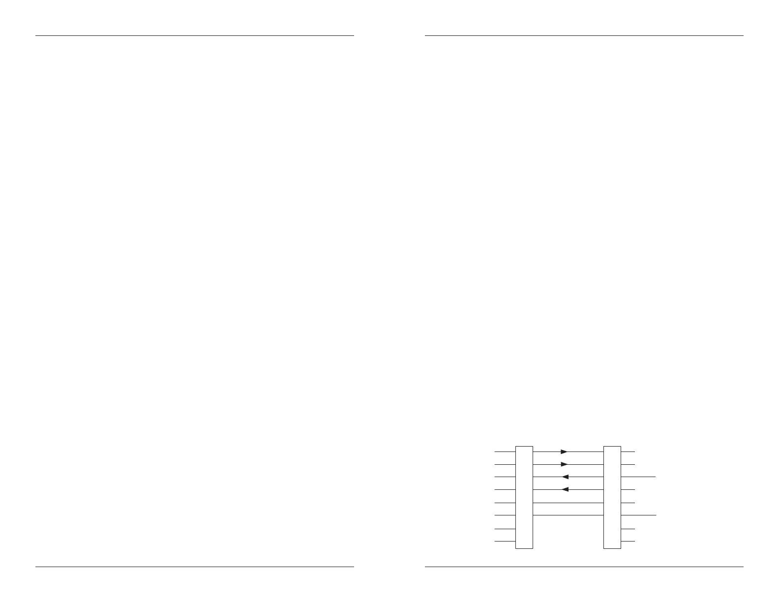
Copper cable
Connector: RJ-45 / RJ-48C
Elec. network connection: Single 4-wire (Tip/Ring - Tip1/Ring1)
Mechanical arrangement: 8-position miniature modular jack
Usage: 1.544 Mb/s or 2.0478 Mb/s access lines
Interface codes: 04DU9 (any applicable)
Cable type:
Long Haul T1: 0db, -7.5dp, -15db, -22db
E1 (120 ohm): E1 3.0V, 120
J1 (110 ohm): 0-655’, 110
DSX-1 (100 ohm): 0-133’, 133-266’, 266-399’, 399-533’, 533-655’
1
2
3
4
5
6
7
8
1
2
3
4
5
6
7
8
R
T
Dry Contact B
Transmit
R1
T1
Dry Contact
Receive
(ring) R
(tip) T
(ring) R1
(tip) T1
(not used)