Honeywell NOTIFIER IFS-2600 User manual
- Category
- Fire protection
- Type
- User manual
This manual is also suitable for

IFS-2600
Fire Indicator Panel
TECHNICAL, PROGRAMMING
& INSTALLATION MANUAL
P/N 10069 ECN08-0066
8/05/08
Rev:
3.01


Installation Precautions
Adherence to the following will aid in
problem-free installation with long-term
reliability:
WARNING - Several different sources of power
can be connected to the fire alarm control
panel. Disconnect all sources of power before
servicing. Control unit and associated equipment
may be damaged by removing and/or inserting
cards, modules, or interconnecting cables while the
unit is energized. Do not attempt to install, service,
or operate this unit until manuals are read and
understood.
Verify that wire sizes are adequate for all
initiating and indicating device loops. Most devices
cannot tolerate more than a 10% I.R. drop from the
specified device voltage.
Like all solid state electronic devices, this
system may operate erratically or can be damaged
when subjected to lightning induced transients.
Although no system is completely immune from
lightning transients and interference, proper
grounding will reduce susceptibility. Overhead or
outside aerial wiring is not recommended, due to
an increased susceptibility to nearby lightning
strikes. Consult with the Technical Services
Department if any problems are anticipated or
encountered.
Disconnect AC power and batteries prior to
removing or inserting circuit boards. Failure to do
so can damage circuits.
Remove all electronic assemblies prior to any
drilling, filing, reaming, or punching of the
enclosure. When possible, make all cable entries
from the sides or rear. Before making
modifications, verify that they will not interfere with
battery, transformer, or printed circuit board
location.
Do not over tighten screw terminals. Over
tightening may damage threads, resulting in
reduced terminal contact pressure and difficulty
with screw terminal removal.
This system contains static-sensitive
components. Always ground yourself with a
proper wrist strap before handling any circuits so
that static charges are removed from the body.
Use static suppressive packaging to protect
electronic assemblies removed from the unit.
Follow the instructions in the installation,
operating, and programming manuals. These
instructions must be followed to avoid damage to
the control panel and associated equipment.
FACP operation and reliability depend upon proper
installation.
This equipment must be correctly programmed
and installed to suit the specific application.
Please ensure correct operational parameters are
set prior to commissioning. If further details on
programming options are required, please consult
the programming manual or contact our helpful
technical support personnel.
EMC WARNING:
This equipment may radiate radio frequency energy. It may also be affected by radio frequency energy and, if
not installed and operated in accordance with the manufacturers instructions, may cause interference to radio
communications. It has been tested and found to comply with the Class A radiated and conducted EMI
requirements of AS/NZ 3548:1995 (including Amendments 1 & 2) as well as the EMI susceptibility
requirements of Clause C3.5 in AS4428.0:1997.
Radio communication devices should not be used in the vicinity of fire panels or associated ancillary devices
and systems.

Documentation Feedback
Your feedback helps us keep our documentation up to date and accurate. If you have any comments or suggestions about
our printed manuals you can email us.
Please include the following information:
Product name and version number (if applicable)
Manual part number and revision (found on the front cover)
Page number
Brief description of the content you think should be improved or corrected
Your suggestion for how to correct/improve documentation
Send email messages to:
techpubs@notifier.com.au
Please note this email address is for documentation feedback only. If you have any technical issues, please contact
you nearest branch for technical support.

IFS-2600 Installation & Programming Manual Page 1
P/N 10069 ECN08-0066
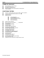
TABLE OF CONTENTS
COMPATIBLE DETECTORS................................................................................................5
OVERVIEW...........................................................................................................................6
CAUTION ........................................................................................................................................................................... 6
SPECIFICATION...................................................................................................................7
APPROVALS...................................................................................................................................................................... 7
ENVIRONMENTAL LIMITS........................................................................................................................................... 7
POWER SUPPLY RATINGS AND SETTINGS ............................................................................................................. 9
INTERNAL 24 VDC (nom) 3.0A MAIN POWER SUPPLY .......................................................................................... 9
INTERNAL 27.3V DC 1.5A BATTERY CHARGER..................................................................................................... 9
Internal 5VDC 2A Power Supply ..................................................................................................................................... 9
EXTERNAL 27VDC POWER SUPPLY....................................................................................................................... 10
BATTERY TYPE AND CAPACITIES .......................................................................................................................... 10
TECHNICAL DESCRIPTION..............................................................................................11
GENERAL ........................................................................................................................................................................ 11
TRANSIENT SUPPRESSION......................................................................................................................................... 11
CURRENT CONSUMPTION......................................................................................................................................... 11
AZF DESCRIPTION........................................................................................................................................................ 12
AZF SUPERVISORY CURRENT .................................................................................................................................. 12
OVERLOAD PROTECTION.......................................................................................................................................... 12
ZONE OVERLOAD SELF RESET................................................................................................................................ 12
PRINTER OUTPUT......................................................................................................................................................... 13
CABLE CONNECTION.................................................................................................................................................. 13
PROGRAMMING BY COMPUTER............................................................................................................................. 13
ALIGNMENT AND ADJUSTMENT.....................................................................................14
PCB2006 POWER SUPPLY BOARD ............................................................................................................................ 14
INTERNAL 24VDC (nom) POWER SUPPLY.............................................................................................................. 14
INTERNAL 27.3 VDC BATTERY CHARGER............................................................................................................ 14
EXTERNAL 24VDC (nom) POWER SUPPLY (if fitted)............................................................................................. 14

Page 2 IFS-2600 Installation & Programming Manual
P/N 10069 ECN08-0066
PCB2005 TERMINATION BOARD...............................................................................................................................14
INTERNAL 5VDC POWER SUPPLY TP8...................................................................................................................14
POWER SUPPLY COMPARATOR REFERENCE VOLTAGE TP10.........................................................................14
NON ADJUSTABLE TEST POINTS..............................................................................................................................14
ALARM THRESHOLD COMPARATOR TP7.............................................................................................................15
FAULT THRESHOLD COMPARATOR TP6 ..............................................................................................................15
CONFIGURATION JUMPERS......................................................................................................................................16
IFS2004 - JP3 DEFAULT .............................................................................................................................................16
IFS2004 - JP4 PROGRAM DISABLE..........................................................................................................................16
IFS2004 - JP5 CPU RESET...........................................................................................................................................16
IFS2005 – JP2 DOOR HOLDER BYPASS...................................................................................................................16
IFS2006 – JP1 EXTERNAL PS MONITORING..........................................................................................................16
IFS804 - JP1-7 ZONE BOARD ADDRESSING...........................................................................................................16
PLACING INTO OPERATION............................................................................................17
EQUIPMENT AS FITTED..............................................................................................................................................17
INITIAL CHECKLIST....................................................................................................................................................17
POWER UP CHECKLIST...............................................................................................................................................18
FUNCTIONAL TESTING...............................................................................................................................................18
FAULT RECORD.............................................................................................................................................................19
INSTRUCTIONS TO OPERATORS....................................................................................20
INDICATORS...................................................................................................................................................................20
SUGGESTED ALARM PROCEDURE..........................................................................................................................21
OPERATOR INSTRUCTIONS.......................................................................................................................................21
FIREFIGHTER FUNCTIONS........................................................................................................................................21
GLOBAL FUNCTIONS.................................................................................................................................................22
ZONE FUNCTIONS.......................................................................................................................................................24
PROGRAMMING................................................................................................................27
GLOBAL OPTIONS.........................................................................................................................................................27
ZONE OPTIONS ..............................................................................................................................................................27
OUTPUT RELAY OPTIONS..........................................................................................................................................28
DEFAULT SETTINGS.....................................................................................................................................................28
PROGRAM MODE..........................................................................................................................................................29
PROGRAMMING MODE..............................................................................................................................................29
PROGRAMMING HIERARCHY..................................................................................................................................29
ZONES............................................................................................................................................................................29
RELAYS.........................................................................................................................................................................30
GLOBAL ........................................................................................................................................................................30
PRINT.............................................................................................................................................................................30

IFS-2600 Installation & Programming Manual Page 3
P/N 10069 ECN08-0066
MAIN MENU.................................................................................................................................................................... 30
EXIT PROGRAMMING MODE................................................................................................................................... 31
ZONE PROGRAMMING................................................................................................................................................ 31
SELECT ZONE #........................................................................................................................................................... 31
ZONE SELECTED......................................................................................................................................................... 31
ZONE TYPE .................................................................................................................................................................. 31
ZONE OUTPUT CONFIGURATION ........................................................................................................................... 32
RELAY PROGRAMMING MODE................................................................................................................................ 32
SELECT RELAY # ........................................................................................................................................................ 32
RELAY SELECTED...................................................................................................................................................... 32
RELAY TYPE................................................................................................................................................................ 33
RELAY MAPPING........................................................................................................................................................ 33
GLOBAL PROGRAMMING.......................................................................................................................................... 33
ACF OUTPUT................................................................................................................................................................ 34
AVF................................................................................................................................................................................ 34
RELAY (GLOBAL RELAY UNITY MAP) .................................................................................................................. 34
PRINT PROGRAMMING DATA .................................................................................................................................. 35
TIME (DATE & TIME)................................................................................................................................................... 35
APPENDIX A ......................................................................................................................36
DESCRIPTION OF ALARM ZONE TYPES................................................................................................................ 36
LATCHING TYPE......................................................................................................................................................... 36
NON LATCHING TYPE ............................................................................................................................................... 36
TIME DELAY AZF........................................................................................................................................................ 37
APPENDIX B ......................................................................................................................38
ZONE OUTPUT CONFIGURATIONS.......................................................................................................................... 38
APPENDIX C ......................................................................................................................39
ALARM VERIFICATION FACILITY (AVF) .............................................................................................................. 39
GLOBAL PROGRAMMABLE OPTIONS.................................................................................................................... 39
APPENDIX D ......................................................................................................................40
ANCILLARY TRIP (ACF)..............................................................................................................................................40
GLOBAL PROGRAMMABLE OPTIONS.................................................................................................................... 40
APPENDIX E.......................................................................................................................41
RELAY OUTPUT MAPPING......................................................................................................................................... 41
AND MAPPING ............................................................................................................................................................... 41
OR MAPPING.................................................................................................................................................................. 41
FAULT MAPPING........................................................................................................................................................... 41
FAULT/ISOLATE MAPPING........................................................................................................................................ 42
ISOLATE MAPPING ...................................................................................................................................................... 42

Page 4 IFS-2600 Installation & Programming Manual
P/N 10069 ECN08-0066
APPENDIX F ......................................................................................................................43
GLOSSARY OF TERMS.................................................................................................................................................43
APPENDIX G......................................................................................................................44
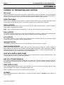
SUMMARY OF TERMINATIONS AND CAUTIONS.................................................................................................44
MCP LOOP.....................................................................................................................................................................44
DETECTION ZONES ....................................................................................................................................................44
RELAY OUTPUTS........................................................................................................................................................44
BELL OUTPUTS ...........................................................................................................................................................44
ACF OUTPUTS..............................................................................................................................................................44
WARNING SYSTEM.....................................................................................................................................................44
DOOR HOLDER OUTPUTS.........................................................................................................................................44
AUXILIARY POWER & MIMIC POWER ...................................................................................................................44
MAF ISOL & TRANSPONDER 0V ..............................................................................................................................44
MIMIC DATA & CLOCK..............................................................................................................................................44
AC INPUT......................................................................................................................................................................44
BATTERY......................................................................................................................................................................45
DOOR HOLDER AC INPUT.........................................................................................................................................45
OUTPUT RELAYS........................................................................................................................................................45
APPENDIX H......................................................................................................................46
IFS-2600 PROGRAMMED OPTIONS...........................................................................................................................46
APPENDIX I........................................................................................................................53
TECHNICAL DRAWINGS.............................................................................................................................................53
MAIN KEYPAD AND DISPLAY..................................................................................................................................53
EXPANSION DISPLAY................................................................................................................................................53
Block Connection Diagram.............................................................................................................................................54
System Sensor Conventional Detector Connection Diagram..........................................................................................54
System Sensor Conventional Detector Connection Diagram..........................................................................................55
Hochiki Conventional Detector Connection Diagram.....................................................................................................55
Hochiki Conventional Detector Connection Diagram.....................................................................................................56
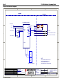
Ancillary Connection Diagram........................................................................................................................................57
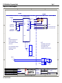
ASE Connection Diagram...............................................................................................................................................58
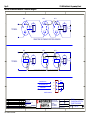
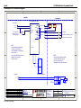
Auto Changeover Dual Sounder Connection Diagram....................................................................................................59
Auto Change Over Dual Sounder Connection Diagram..................................................................................................60
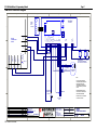
MIMIC Connection Diagram..........................................................................................................................................61
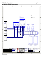
Single Fan Connection Diagram.....................................................................................................................................62
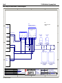
Dual Fan Connection Diagram........................................................................................................................................63
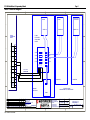
Exhaust Fan Connection Diagram...................................................................................................................................64
Supply Fan Connection Diagram....................................................................................................................................65
Smoke Spill Fan Connection Diagram............................................................................................................................66
10W EVAC Connection Diagram...................................................................................................................................67
10W EVAC Slave Connection Diagram.........................................................................................................................68
30W EVAC Connection Diagram...................................................................................................................................69
30W EVAC Slave Connection Diagram.........................................................................................................................70
50W EVAC Connection Diagram...................................................................................................................................71
50W EVAC Slave Connection Diagram.........................................................................................................................72

IFS-2600 Installation & Programming Manual Page 5
P/N 10069 ECN08-0066
COMPATIBLE DETECTORS
Make Model Type Model Number
System Sensor Thermal Type A 5451 AUS
System Sensor Thermal Type A 51A51
System Sensor Thermal Type B 4451 AUS
System Sensor Thermal Type B 51B51
System Sensor Thermal Type B Sealed 51B51S
System Sensor Thermal Type C 51C51
System Sensor Thermal Type D 51D51
System Sensor Smoke Photo-Optical 2151 AUS
System Sensor Smoke Photo-Optical 2151B AUS
System Sensor Smoke Ionisation 1151 AUS
System Sensor Thermal Type D 51D51
System Sensor Smoke Beam BEAM1224
System Sensor Smoke Duct DHP-100
Apollo Thermal Type A Series 60
Apollo Thermal Type B Series 60
Apollo Thermal Type C Series 60
Apollo Thermal Type D Series 60
Apollo Smoke Ionisation Series 60
Apollo Smoke Photo Optical Series 60
Hochiki Thermal Type A DCA-B-60R MkV
Hochiki Thermal Type A DCC-A
Hochiki Thermal Type A DCD-A
Hochiki Thermal Type B DFE-60B
Hochiki Thermal Type B DFJ-60B
Hochiki Thermal Type C DCA-B-90R Mk1
Hochiki Thermal Type C DCC-C
Hochiki Thermal Type C DCD-C
Hochiki Thermal Type D DFE-90D
Hochiki Thermal Type D FDJ-90D
Hochiki Thermal Cool Room Type B sealed DFG-60BLKJ
Hochiki Smoke Ionisation SIH-AM
Hochiki Smoke Ionisation SIJ-ASN
Hochiki Smoke Photo Optical SLK-A
Hochiki Smoke Photo Optical SLR-AS
Olsen Thermal Type A T56B-T6A
Olsen Thermal Type B T56B-T6B
Olsen Thermal Type C T56B-T6C
Olsen Thermal Type D T56B-T6D
Olsen Smoke Ionisation C24B
Olsen Smoke Photo Optical P24B
Panelect Thermal Type A PFS-A
Panelect Thermal Type B PFS-B
Panelect Thermal Type C PFS-C
Panelect Thermal Type D PFS-D
Panelect Smoke Ionisation PFS-I
Panelect Smoke Ionisation PFS-I , MkII
Panelect Smoke Photo Optical PFS-P
Panelect Smoke Photo Optical PFS-P, MkII
IEI VESDA E700, E70D CONTACT DEVICE
Please contact NOTIFIER INERTIA for any additional detectors.

Page 6 IFS-2600 Installation & Programming Manual
P/N 10069 ECN08-0066
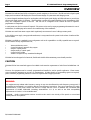
OVERVIEW
IFS-2600 Fire Indicator Panel (FIP) is designed to provide simplicity to the end user. The FIP uses both a liquid crystal
display and conventional LED displays for fast and accurate display of system status and changing events.
A custom designed membrane keypad is used together with the liquid crystal display and LED indicators to provide fast,
efficient and simple modes of operation. The keypad also provides the required flexibility for the programming of the
many user configurable options of this FIP. The FIP can be configured on-site without the need of expensive
programmers or components.
A serial printer can also be connected if required. The printer can be used to output programming information for ease of
modification, for safekeeping and to assist in the commissioning of the installation.
IFS-2600 uses serial chain mimic outputs which significantly saves time and costs of cabling to mimic panels.
A door holder power supply (using optional transformer) is incorporated into the system for the release of smoke and fire
doors on alarm.
IFS-2600 is available in a standard 8-zone configuration and can be expandable to its fully expanded state as required.
The IFS-2600 in its fully expanded state can;
• Monitor 64 detection zones
• Control 64 optional "mapped" relay outputs
• Output to a serial printer
• Output serially to a mimic panel
• Control to door holders
• Interface as required to any Australian Fire Brigade
IFS-2600 has been designed to be functional, flexible and reliable whilst maintaining a user-friendly interface.
CAUTION
IFS-2600 FIP has been tested and approved to AS4428.1 and meets the requirements of AS1670 and AS1668 Parts 1 &
2.
However, the equipment must be correctly programmed and installed to suit the specific application. Please ensure
correct operational parameters are set prior to commissioning. If further details on programming options are required,
please consult the programming manual or contact our helpful technical support personnel.
WARNING:
This equipment may radiate radio frequency energy. It may also be affected by radio frequency energy and, if
not installed and operated in accordance with the manufacturers instructions, may cause interference to radio
communications. It has been tested and found to comply with the Class A radiated and conducted EMI
requirements of AS/NZ 3548:1995 (including Amendments 1 & 2) as well as the EMI susceptibility
requirements of Clause C3.5 in AS4428.0:1997
CAUTION: Radio communication devices should not be used in the vicinity of fire panels or associated
ancillary devices and systems

IFS-2600 Installation & Programming Manual Page 7
P/N 10069 ECN08-0066
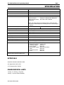
SPECIFICATION
Cabinet Zinc Sealed Steel 1.6mm
Powder Coated
Hinged Inner Door
Hinged Outer Door
Outside Dimensions 2608 (8 zones) 394mm H x 390mm W x 180mm D*
2624 (24 zones) 750mm H x 390mm W x 180mm D*
2600 (32 to 64 zones) 18U, 28U & 40U Cabinets
Battery Box
*Note: the depth quoted is including the door and break glass.
The internal cabinet depth not including he door and break glass
is 140mm.
AC Operational Voltage 240 VAC 50Hz + 10%
Internal Power Supplies Battery Charger 27.3 VDC 1.5AMP
Panel Supply 24 VDC(nom) 3.0AMP
Logic Supply 5 VDC 2.0AMP
Microprocessor 80C52
Memory Type Non-volatile E
2
ROM
Liquid Crystal Display 2 Lines x 16 Characters LED Backlit
Fuses F1: Panel Supply M205 5A
F2: Battery Charger M205 3A
F3: Battery Protection Polyfuse 3A
F4: External Supply M205 7A
F5: Door Holder M205 3A
F6: Aux Power Output M205 1A Slow Blow
F7: Bell M205 1A
F8: Warning System M205 1A
F9: ACF M205 1A
E.O.L Resistor On AZFs, monitored
outputs, Bells, Warning system, ACF
4K7 Ohms
APPROVALS
Australian Standard AS4428.1 1998
SSL Approval No AFP-1553
C-Tick Approval No. N1336
ENVIRONMENTAL LIMITS
-10 Deg. C to +55 Deg. C Dry heat.
+40 Deg. C @ 93% Relative Humidity.

Page 8 IFS-2600 Installation & Programming Manual
P/N 10069 ECN08-0066
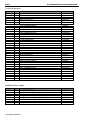
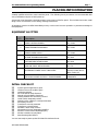
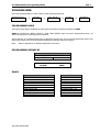
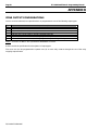
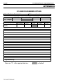
SYSTEM EXPANSION
Zones Qty Hardware Required Product Code
8 1 Main Control Board PCB-2004
1 Main Termination board PCB-2005
1 Power Supply board PCB-2006
16 1 Main Control board PCB-2004
1 Main Termination board PCB-2005
1 Power Supply board PCB-2006
1 8 Zone Expansion board PCB-804G3
1 16 Zone Indicator board PCB-816
24 1 Main Control board PCB-2004
1 Main Termination board PCB-2005
1 Power Supply board PCB-2006
2 8 Zone Expansion board PCB-804G3
1 16 Zone Indicator board PCB-816
32 1 Main Control board PCB-2004
1 Main Termination board PCB-2005
1 Power Supply board PCB-2006
3 8 Zone Expansion board PCB-804G3
2 16 Zone Indicator board PCB-816
40 1 Main Control board PCB-2004
1 Main Termination board PCB-2005
1 Power Supply board PCB-2006
4 8 Zone Expansion board PCB-804G3
2 16 Zone Indicator board PCB-816
48 1 Main Control board PCB-2004
1 Main Termination board PCB-2005
1 Power Supply board PCB-2006
5 8 Zone Expansion board PCB-804G3
3 16 Zone Indicator board PCB-816
56 1 Main Control board PCB-2004
1 Main Termination board PCB-2005
1 Power Supply board PCB-2006
6 8 Zone Expansion board PCB-804G3
3 16 Zone Indicator board PCB-816
64 1 Main Control board PCB-2004
1 Main Termination board PCB-2005
1 Power Supply board PCB-2006
7 8 Zone Expansion board PCB-804G3
4 16 Zone Indicator board PCB-816
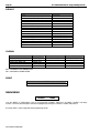
Additional relay outputs:
Relays Qty Hardware Required Product Code
8 1 Relay board containing 8 relays 24VDC 1A IFS-717
16 2 Relay board containing 8 relays 24VDC 1A IFS-717
24 3 Relay board containing 8 relays 24VDC 1A IFS-717
32 4 Relay board containing 8 relays 24VDC 1A IFS-717
40 5 Relay board containing 8 relays 24VDC 1A IFS-717
48 6 Relay board containing 8 relays 24VDC 1A IFS-717
56 7 Relay board containing 8 relays 24VDC 1A IFS-717
64 8 Relay board containing 8 relays 24VDC 1A IFS-717

IFS-2600 Installation & Programming Manual Page 9
P/N 10069 ECN08-0066
POWER SUPPLY RATINGS AND SETTINGS
INTERNAL 24 VDC (nom) 3.0A MAIN POWER SUPPLY
This supply's primary function is to power panel logic and all external operations of the FIP, i.e.: detection
circuits, ancillary circuits, etc. This supply meets the requirements of AS4428.5.
AC Input 30 VAC +10% - 15%
Output Current 3.0 AMPS
Output Voltage 26.5 VDC
Current Limit 3.0 AMPS
Output Ripple 50 mV
INTERNAL 27.3V DC 1.5A BATTERY CHARGER
Its primary function is to charge the batteries. This supply meets the requirements of AS4428.5.
AC Input 30 VAC +10% -15%
Output Current 1.5 AMPS
Output Voltage 27.3 VDC
Current Limit 1.5 AMPS
Output Ripple 200 mV
Important Note:
After a power failure, the battery will only reconnect to the charger if the battery voltage is above approximately
20V +/- 2V.
A battery fault will be generated in the event that the battery does not automatically reconnect. This is to ensure
that a faulty or dead flat battery (due to an extended power failure) does not bring the entire system down.
In order to reconnect a flat battery, it is necessary to disconnect the battery from the panel and charge it
externally. The battery should be thoroughly tested before returning it to service.
In the event that an external charger is not available, the battery may be trickle charged above 22V via a 30
ohm, 5W resistor connected between the 24v Aux Output and the battery positive terminal. A 1N4004 Diode
(Notifier part number #286) or similar should also be fitted in series with the resistor to stop the battery from
pulling down the main panel voltage. Trickle charging the battery by this method may take several hours to
bring it up to the minimum level.
The battery can then be reconnected to the panel for charging via the internal battery charger. It is important
that the voltage on the battery be monitored to ensure that it is charging. The battery should then be left for 24
hours and then fully tested to ensure that no damage has occurred due to the deep discharge.
Internal 5VDC 2A Power Supply
This supply's primary function is to power all internal operations of the FIP, i.e.: Microprocessor, liquid crystal
display, LED's keypad etc.
AC Input 30 VAC +15% or 27.6VDC+15%
Output Current 2.0 AMPS
Output Voltage 5.0 VDC
Current Limit 2.0 AMPS
Output Ripple 150 mV

Page 10 IFS-2600 Installation & Programming Manual
P/N 10069 ECN08-0066
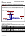
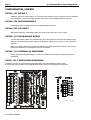
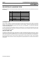
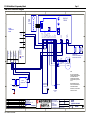
EXTERNAL 27VDC POWER SUPPLY
This supply is used in addition to the internal power supply for large systems. Its primary function is to power
any additional ancillary loads of the FIP up to 7 amps. This supply meets the requirements of AS4428.5
Important Notes:
When using external power supply, JP1 link on IFS2006E must be fitted to enable external PSU monitoring.
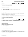
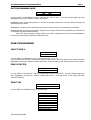
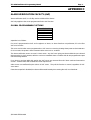
If this supply is used to power a NI-2008 gas module, the following additional components are required to
ensure a break free change over from the mains supply to the panel battery in case of mains fail condition.
1. A 6A4 or P600G rectifier diode (Notifier part number #266) is to be installed in series with the
external +27V output of the IFS-2600 termination board.
2. A 3300µF 50V Electrolytic Capacitor (Notifier part number #1248) should be installed across the
+27V and 0V of the ancillary device.
BATTERY TYPE AND CAPACITIES
In general, any Sealed Lead Acid Battery, or Wet Lead Acid Battery designed for stationary use is compatible
with the IFS-2600 Fire Indicator Panel. Automotive batteries must not be used. The use of Nickel Cadmium
batteries is not recommended.
Manufacturer Type Number Voltage Capacity (Ah) Qty Required
Best and Best Sealed LA BP17-12 12 17 2
Best and Best Sealed LA BP24-12 12 24 2
Best and Best Sealed LA BP40-12 12 40 2
Olympic Batteries Sealed LA CJ12-7 12 7 2
Olympic Batteries Sealed LA CJ12-12 12 12 2
Olympic Batteries Sealed LA CJ12-18 12 18 2
Olympic Batteries Sealed LA CJ12-26 12 26 2
Olympic Batteries Sealed LA CJ12-33 12 33 2
Olympic Batteries Sealed LA CJ12-40 12 40 2
Olympic Batteries Sealed LA CJ12-88 12 88 2
Olympic Batteries Sealed LA CJ12-100 12 100 2
AC
INPUT
24V 0V
-+
24V 0V
REMOTE
OUTPUT
REMOTE
INPUT
BATT
INPUT
EXTERNAL
POWER
SUPPLY
24V
0V
OUTPUT
+
24V
0
V
POWER IN
NI-2008 GAS
SUPPRESSION
MODULE
3300uF
6A4
IFS
-
2600 TERMINATION BOARD

IFS-2600 Installation & Programming Manual Page 11
P/N 10069 ECN08-0066
TECHNICAL DESCRIPTION
GENERAL
The IFS-2600 in its most basic form comprises of three boards, the main control board, the main termination
board and the power supply board.
The main control board contains the Microprocessor, EPROM, RAM and E
2
ROM. The main control board also
has the liquid crystal display and keypad attached. All of the "delicate" electronics have been placed on this
board. The main control board complete with the inner door is easily removed during installation to avoid
damage and allow greater access to the field terminals.
The main termination board contains the one power supply for 5V logic, and connectors for a Power Supply
and Battery Charger daughter board, the first eight zones, all common outputs and the printer interface. All
charger settings, fuses etc are located on this board. The Power Supply and Battery Charger board contains
two switch mode regulators, 26.5V for the panel power, 27.3V for the battery charger.
Up to seven (7) zone expansion boards can be added to the system to increase its detection capability. These
boards contain the same electronics as on the main termination board for zone scanning. Addressing is by a
jumper that selects which group of eight zones the board refers to.
Up to four (4) zone indicator boards can also be added. These boards will display the status of the zone
expansion boards fitted.
Up to eight (8) relay boards can be added. These boards contain 8 change-over relay contacts, each rated at
1 amp. These boards require no addressing, as they work on a serial data chain. Output 1 is the closest
output to the main board.
NOTE This product utilises state of the art components and materials and therefore boards must be returned
to our factory for proper troubleshooting, repair and retesting. Field component level repairs are not
recommended and would void all warranties on the product.
TRANSIENT SUPPRESSION
The IFS-2600's superior transient protection comprises of Dual Transorb input traps, inductive paths on
incoming PCB tracks, circuit board planes and metal oxide varistors on outputs. These devices are all self-
resetting.
CURRENT CONSUMPTION
Zones Fitted Quiescent Current Quiescent + 2 AZF'S in alarm +1A of Bell +1 Amp ACF
8 150 mA 2.23 AMPS
16 250 mA 2.33 AMPS
24 350 mA 2.43 AMPS
32 450 mA 2.53 AMPS
40 550 mA 2.63 AMPS
48 650 mA 2.73 AMPS
56 750 mA 2.83 AMPS
64 850 mA 2.93 AMPS
Note:
1: Each installation would require individual battery calculations to be performed for load capacity and
power supply capacity.
2: Each IFS-717 relay board, can add 370 mA (in alarm and quiescent) current per board.

Page 12 IFS-2600 Installation & Programming Manual
P/N 10069 ECN08-0066
AZF DESCRIPTION
The AZF's on the IFS-2600 are monitored and scanned by custom thick film hybrids. These hybrid IC's
significantly reduce the possibility of false alarms and improve product efficiency and reliability.
The total Alarm Zone loop resistance is the sum of the end of line resistor (EOLR 4K7) plus all the parallel
connected detector loads.
AZF SUPERVISORY CURRENT
The supervisory current flows through the external terminal AZF+, through the field cable and to the end of line
resistor (EOLR), returning to the panel at AZF- terminal. Parallel connected, across the 2-wire pair field cable,
are a number of the previously listed detectors. During the quiescent state there is essentially an open circuit
across the + and - terminals of the detector base. The maximum number of detectors that can be installed on
each AZF is dependant on the type of detector and is listed in the IFS-2600 ActivFire
®
listing.
In an alarm state, a 560-ohm resistor is connected across the detector base causing additional loop current to
flow. This is sensed by the AZF to produce an alarm output. Removal of the E.O.L. resistor (in a non alarm
state) or the interruption of the supervisory current will produce a fault signal in the AZF.
As described above, the level of current is used to define the status of the alarm zone: -
I = 3.5 mA and below FAULT
I = 4.0 - 5.0mA at 24V QUIESCENT
I = 16 mA to 40 mA (current limited) ALARM
The zone current is used by the hybrid IC to determine the condition of the zone as above. This information is
then transferred to the microprocessor for processing.
OVERLOAD PROTECTION
Panel Supply Fuse F1 M205 5A
Battery Charger Fuse F2 M205 3A
Battery Protection Fuse F3 Polyfuse 3A
External Supply Fuse F4 M205 7A
Door Holder Fuse F5 M205 3A
Aux Power Output Fuse F6 M205 1A Slow Blow
Bell Fuse F7 M205 1A
Warning System Fuse F8 M205 1A
ACF Fuse F9 M205 1A
AZF Circuits Current Limited 40mA
ZONE OVERLOAD SELF RESET
If a zone is overloaded by an accidental short to earth on an AZF circuit, the zone will automatically shut down
and produce a fault. Once this happens the panel will automatically recheck the zone every 60 seconds and
once the overload is removed, restore power and the fault will clear.

IFS-2600 Installation & Programming Manual Page 13
P/N 10069 ECN08-0066
PRINTER OUTPUT
The printer port is designed to be used during testing and commissioning of the panel. The serial printer will
report alarms and faults together with the date and time of the event. The printer can also be used during
“walk test” mode to produce a history of the test and can also be used to print current programming
configuration.
A DB9 plug male is provided at the top of the main termination board. This communication port will
communicate with an IBM compatible serial printer (ASCII printer) with the following settings.
Baud Rate 1200 bps
Data Bits 8
Stop Bits 1
Parity None
Handshaking DTR
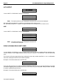
CABLE CONNECTION
Cabling to the printer requires a 4-core telephone style cable with a maximum length of 10 metres. A DB9
socket is required at the panel end. The printer end is dependent on the type of printer used but is usually a
male DB25. Connection is as follows. A 5-core cable can be used for both comms and printer functions
IFS-2600 END PRINTER END
DB9 FEMALE DB25 MALE DB9 MALE
2 RX (only for programming) 2 3
3 TX 3 2
5 GND 7 5
7 RTS ( do not use) (5) (8)
8 CTS ( only for printer) 4 7
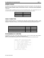
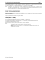
PROGRAMMING BY COMPUTER
Programming of the zones, relays, global functions and time can by set with the DOS based program
“2600/SW” using the printer port. (Cannot be used with Windows XP)
After the cable is installed, the program can be run and the menu will prompt for the available functions.
2600

Page 14 IFS-2600 Installation & Programming Manual
P/N 10069 ECN08-0066
ALIGNMENT AND ADJUSTMENT
PCB2006 POWER SUPPLY BOARD
INTERNAL 24VDC (nom) POWER SUPPLY
With batteries disconnected and no alarms present, measure voltage across the 0V and MAIN test
points on the 2006 power supply board and, if necessary, adjust the multi-turn potentiometer VR2 until
voltage is 26.5V 0.05V (26.45V – 26.55V).
Current limiting is fixed and field adjustment is not possible.
INTERNAL 27.3 VDC BATTERY CHARGER
With batteries disconnected and no alarms present, measure voltage across the 0V and CHARG test
points on the 2006 power supply board and, if necessary, adjust the multi-turn potentiometer VR1 until
voltage is 27.3V 0.05V (27.25V – 27.35V).
Current limiting is factory preset and field adjustment is not required.
EXTERNAL 24VDC (nom) POWER SUPPLY (if fitted)
With batteries disconnected and no alarms present, measure voltage across Remote Input terminals
on PCB2005 and adjust the voltage on the external power supply until the voltage is 26.5V 0.5V
(26.0V – 27.0V). Note: This voltage is not critical for the operation of the IFS-2600 panel, but the
voltage must not go outside the limits as specified for the field ancillaries that it powers.
PCB2005 TERMINATION BOARD
INTERNAL 5VDC POWER SUPPLY TP8
All parameters are fixed and field adjustment is not possible.
POWER SUPPLY COMPARATOR REFERENCE VOLTAGE TP10
With the panel in the quiescent mode, measure voltage between system 0V and TP10. Adjust multi-
turn potentiometer VR3 until voltage is 7.0V 1% (6.93V – 7.07V)
NON ADJUSTABLE TEST POINTS
TP8 = 5.0 VDC 5% 5VDC POWER SUPPLY
TP5 = 12.0 VDC 5% 12VDC POWER SUPPLY
(If these test point voltages are not correct, please return the main termination board to the factory for
repair.)

IFS-2600 Installation & Programming Manual Page 15
P/N 10069 ECN08-0066
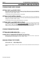
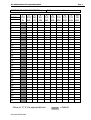
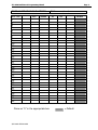
ALARM THRESHOLD COMPARATOR TP7
With the panel in the quiescent mode, measure and take note of the INTERNAL 24V DC POWER
SUPPLY as above.
Measure voltage between system 0V and TP7. Adjust multi-turn potentiometer VR4, and adjust until
the voltage is as per the following table.
Rail Voltage 3.3V Setting Range
20.6 2.833 2.80 to 2.86
21.0 2.888 2.86 to 2.92
21.5 2.956 2.93 to 2.99
22.0 3.025 2.99 to 3.06
22.5 3.094 3.06 to 3.12
23.0 3.163 3.13 to 3.19
23.5 3.231 3.20 to 3.26
24.0 3.300 3.27 to 3.33
24.5 3.369 3.34 to 3.40
25.0 3.438 3.40 to 3.47
25.5 3.506 3.47 to 3.54
26.0 3.575 3.54 to 3.61
26.5 3.644 3.61 to 3.68
27.0 3.713 3.68 to 3.75
27.5 3.781 3.74 to 3.82
27.6 3.795 3.76 to 3.83
28.0 3.850 3.81 to 3.89
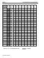
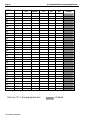
FAULT THRESHOLD COMPARATOR TP6
With the panel in the quiescent mode, measure and take note of the INTERNAL 24V DC POWER
SUPPLY as above.
Measure the voltage between system 0V and TP6. Adjust multi-turn potentiometer VR1, and adjust
until the voltage is as per the following table.
Rail Voltage 0.6V Setting Range
20.6 0.600 0.59 to 0.61
21.0 0.612 0.61 to 0.62
21.5 0.626 0.62 to 0.63
22.0 0.641 0.63 to 0.65
22.5 0.655 0.65 to 0.66
23.0 0.670 0.66 to 0.68
23.5 0.684 0.68 to 0.69
24.0 0.699 0.69 to 0.71
24.5 0.714 0.71 to 0.72
25.0 0.728 0.72 to 0.74
25.5 0.743 0.74 to 0.75
26.0 0.757 0.75 to 0.76
26.5 0.772 0.76 to 0.78
27.0 0.786 0.78 to 0.79
27.5 0.801 0.79 to 0.81
27.6 0.804 0.80 to 0.81
28.0 0.816 0.81 to 0.82

Page 16 IFS-2600 Installation & Programming Manual
P/N 10069 ECN08-0066
CONFIGURATION JUMPERS
IFS2004 - JP3 DEFAULT
Holding a short across these pins for 5 seconds during start-up causes the panel to reset to standard
factory defaults. The panel will give 4 beeps after reset, to acknowledge default on start-up.
IFS2004 - JP4 PROGRAM DISABLE
When fitted, jumper between these pins to inhibit program changes.
IFS2004 - JP5 CPU RESET
With panel operating, a momentary short across these pins will cause a CPU restart.
IFS2005 – JP2 DOOR HOLDER BYPASS
If zoned door holder outputs are required and is to be done external to the main termination board,
then the main door holder release needs to be disabled. Fitting a link across JP2 on IFS2005 PCB
does this.
Note: Door holder output is only enabled if optional door holder transformer is fitted. SW1 must be
linked on PCB2004 CPU board prior to Version 6 Firmware.
IFS2006 – JP1 EXTERNAL PS MONITORING
When using external power supply, JP1 link on IFS2006E must be fitted to enable external PSU
monitoring.
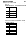
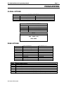
IFS804 - JP1-7 ZONE BOARD ADDRESSING
Jumper JP1 to JP7 on zone expansion board IFS-804 selects the addressing for the zones.
Place jumper in link position for the appropriate 8 zones to which the expansion board applies.
Page is loading ...
Page is loading ...
Page is loading ...
Page is loading ...
Page is loading ...
Page is loading ...
Page is loading ...
Page is loading ...
Page is loading ...
Page is loading ...
Page is loading ...
Page is loading ...
Page is loading ...
Page is loading ...
Page is loading ...
Page is loading ...
Page is loading ...
Page is loading ...
Page is loading ...
Page is loading ...
Page is loading ...
Page is loading ...
Page is loading ...
Page is loading ...
Page is loading ...
Page is loading ...
Page is loading ...
Page is loading ...
Page is loading ...
Page is loading ...
Page is loading ...
Page is loading ...
Page is loading ...
Page is loading ...
Page is loading ...
Page is loading ...
Page is loading ...
Page is loading ...
Page is loading ...
Page is loading ...
Page is loading ...
Page is loading ...
Page is loading ...
Page is loading ...
Page is loading ...
Page is loading ...
Page is loading ...
Page is loading ...
Page is loading ...
Page is loading ...
Page is loading ...
Page is loading ...
Page is loading ...
Page is loading ...
Page is loading ...
Page is loading ...
Page is loading ...
Page is loading ...
Page is loading ...
Page is loading ...
-
 1
1
-
 2
2
-
 3
3
-
 4
4
-
 5
5
-
 6
6
-
 7
7
-
 8
8
-
 9
9
-
 10
10
-
 11
11
-
 12
12
-
 13
13
-
 14
14
-
 15
15
-
 16
16
-
 17
17
-
 18
18
-
 19
19
-
 20
20
-
 21
21
-
 22
22
-
 23
23
-
 24
24
-
 25
25
-
 26
26
-
 27
27
-
 28
28
-
 29
29
-
 30
30
-
 31
31
-
 32
32
-
 33
33
-
 34
34
-
 35
35
-
 36
36
-
 37
37
-
 38
38
-
 39
39
-
 40
40
-
 41
41
-
 42
42
-
 43
43
-
 44
44
-
 45
45
-
 46
46
-
 47
47
-
 48
48
-
 49
49
-
 50
50
-
 51
51
-
 52
52
-
 53
53
-
 54
54
-
 55
55
-
 56
56
-
 57
57
-
 58
58
-
 59
59
-
 60
60
-
 61
61
-
 62
62
-
 63
63
-
 64
64
-
 65
65
-
 66
66
-
 67
67
-
 68
68
-
 69
69
-
 70
70
-
 71
71
-
 72
72
-
 73
73
-
 74
74
-
 75
75
-
 76
76
-
 77
77
-
 78
78
-
 79
79
-
 80
80


Honeywell NOTIFIER IFS-2600 User manual
- Category
- Fire protection
- Type
- User manual
- This manual is also suitable for
Ask a question and I''ll find the answer in the document
Finding information in a document is now easier with AI
Other documents
-
Notifier Fire Panel User manual
-
-
Vizio HDX20L Quick Setup Manual
-
 Firesense IFS- Panel V User manual
-
Altronix AL125ULB Datasheet
-
Omega PTC-16-A-Timer Owner's manual
-
Ampac ZoneSense PLUS AS Programming Manual
-
Brigade BE-500XC (2826B)(2828B) Installation guide
-
 Firesense Fire Panel e User manual
-
Chamberlain LiftMaster LM21XP User manual

