Page is loading ...

ELECTROSTATIC FIELD
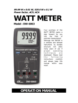
METER
Model : ESF-106
Your purchase of this
ELECTROSTATIC FIELD
METER marks a step
forward for you into the
field of precision
measurement. Although
this METER is a complex
and delicate instrument,
its durable structure will
allow many years of use
if proper operating
techniques are
developed. Please read
the following
instructions carefully
and always keep this
manual within easy
reach.
OPERATION MANUAL

TABLE OF CONTENTS
1. FEATURES.................................................................
.
1
2. SPECIFICATIONS........................................................1
2-1 General specifications...........................................1
2-2 Electrical specifications.........................................2
3. FRONT PANEL DESCRIPTION......................................
.
3
3-1 Display............................................................... 3
3-2 GROUND point.....................................................3
3-3 POWER / Backli
g
ht button....................................
.
3
3-4 HOLD button.......................................................
.
3
3-5 RECORD button ( MAX. / MIN. )............................3
3-6 ZERO button........................................................3
3-7 button..............................................................▲ 3
3-8 ALARM button......................................................3
3-9 button..............................................................▼ 3
3-10 SENSE disc.........................................................
.
3
3-11 Ma
g
netic SPACER................................................3
3-12 RS-232 output terminal.......................................
.
3
3-13 RESET button......................................................3
3-14 GROUND terminal...............................................
.
3
3-15 Stand.................................................................
.
3
3-16 Battery Cover / Compartment..............................
.
3
3-17 EARTH wire........................................................
.
3
3-18 Alli
g
ator clip........................................................3
4. MEASURING PROCEDURE...........................................
.
4
4-1 Power ON / OFF...................................................4
4-2 Groundin
g
...........................................................
.
4
4-3 Zero procedure....................................................
.
4
4-4 STATIC Volta
g
e measurement procedure...............4
4-5 ALARM Settin
g
procedure.....................................
.
5
4-6 Data Hold............................................................ 5
4-7 Data Record ( Max. , Min. readin
g
).......................5
4-8 LCD Backli
g
ht .....................................................
.
6
5. SYSTEM RESET..........................................................
.
6
6. MAINTENANCE...........................................................7
7. RS232 PC SERIAL INTERFACE..................................... 7
8. BATTERY REPLACEMENT............................................
.
8

1. FEATURES
* Professional precision STATIC Voltage meter with 0.001 kV
resolution.
* LSI - circuit provides high reliability and durability.
* Measurement range : -19.999 kV to +19.999 kV.
* High voltage alarm : +/- 18.000 kV.
* ALARM setting : 0.010 kV to 18.000 kV.
* Data hold , Records ( Max. & Min.).
* LCD with green backlight.
* RS232 / USB Computer interface.
* Built-in low battery indicator.
* Power : (1) 9V alkaline or equivalent.
2. SPECIFICATIONS
2-1 General Specifications
Display LCD size : 51 mm x 30 mm ,
Max. indication : ± 19999.
LCD with backlight ( On/Off ).
Circuit Custom one-chip of microprocessor
LSI circuit.
Measurement Static Voltage :
-19.999 kV to +19.999 kV
Over input " ---- " mark indication.
Zero adjustment ZERO button.
Sampling time Approx. 0.5 second .
Data hold Freeze the display reading.
Memory recall Maximum and Minimum value.
Data output RS232/USB PC Computer interface.
* Connect the optional RS232 cable
UPCB - 02 will get the RS232 plug.
* Connect the optional USB cable
USB - 01 will get the USB plug.
1

Operation Temp. 0 to 50 ( 32 to 122 ).℃℃℉ ℉
Operation Less than 70% RH, non-condensing.
humidity
Power supply Alkaline or Heavy duty type DC 9V
battery.
006P , MN1604 (PP3) or equivalent
Power Approx. DC 6 mA
consumption
Weight 215 g / 0.476 LB
Dimension 195x68x30 mm ( 7.6x2.6x1.2 inch ).
Accessories Instruction manual................
.
1 PC
included 1" Ma
g
netic Spacer................ 1 PC
Ground wire.......................... 1 PC
Ground CLIP.........................
.
1 PC
Carryin
g
case, CA-06............. 1 PC
Optional * USB cable, USB-01
accessories * RS232 cable, UPCB-02
* Data Acquisition software,
SW-U801-WIN.
* Excel Data Acquisition software,
SW-E802.
2-2 Electrical Specifications
Static Voltage
Range Resolution Accuracy
+19.999 to -19.999 kV 0.001 kV ± ( 5%+50d )
Remark :
* Accuracy @ 23 ± 5℃℃
* The above spec. accuracy are tested under the
environment . RF Field Strength less than 3 V/M &
frequency less than the 30 MHz only .
2

3. FRONT PANEL DESCRIPTION
Fig. 1
3-1 Display
3-2 GROUND point
3-3 POWER / Backlight button
3-4 HOLD button
3-5 RECORD button ( MAX. / MIN. )
3-6 ZERO button
3-7 button▲
3-8 ALARM button
3-9 button▼
3-10 SENSE disc
3-11 Magnetic SPACER
3-12 RS-232 output terminal
3-13 RESET button
3-14 GROUND terminal
3-15 Stand
3-16 Battery Cover / Compartment
3-17 EARTH wire
3-18 Alligator clip
3

4. MEASURING PROCEDURE
4
4-1 Power ON /OFF
1.
Press the "POWER / Backlight button" (3-3 , Fig. 1) more than 2
seconds to Turn ON the meter.
2. Press the "POWER / Backlight button" (3-3 , Fig. 1) more than 2
seconds to Turn OFF the meter.
3 If no buttons are pressed in 10 minutes, meter will AUTO POWER OFF
to save battery and meter life.
4-2 Grounding
Before using the meter it is necessary to install the grounding the meter.
Choose one of the below two methods. Number 1 is the recommended
method.
1. Use the accessories EARTH wire (3-17 , Fig.1) to connect to the
building's EARTH ground from the meter "GROUND terminal" (3-14 ,
Fig.1). ie. From electrical outlet ground terminal.
2 Operator is attached to the EARTH ground by way of an Anti-static
wrist strap (not provided), and finger placed on the "GROUND
point" (3-2 , Fig.1).
4-3 Zero procedure
Before you measure the STATIC Voltage. If the meter has a reading on
the screen .You can press the 'ZERO' button (3-6 , Fig.1) once to clear
the reading.
4-4 STATIC Voltage measurement procedure
When measuring the STATIC Voltage . use the "Magnetic
SPACER" (3-11 , Fig.1) to magnetically attach to the back of the meter,
just below the "SENSE disk" (3-10 , Fig.1).
Distance between "SENSE disk" (3-10 , Fig.1) and test area is 1 inch
(2.54 cm).
1. Press the "POWER / Backlight button" (3-3 , Fig.1) more than 2
seconds to Turn ON the meter.
2. Make sure the meter is grounded before operation.
3. Aim the "SENSE disk" (3-10 , Fig.1) toward the object (without
touching the disk).

4. Keep your fingers away from the test area to avoid
accidental discharge .
5. STATIC Voltage will be displayed on the screen .
4-5 ALARM Setting procedure
1. This meter has HIGH Voltage WARNING function . When
reading is over 18.000 kV . the meter will beep to user .
( this meter can reading over 19.990 kV.)
2. To change the voltage value to limit you can press the "
ALARM button " ( 3-8 , Fig.1) more than 2 seconds to
Turn ON the setting function and ALARM symbol will
luminate. The first digit of alarm value will flash . Now
you can press the " ▲ button " ( 3-7 ,
Fig.1) to increase the value . or press the " button " (▼
3-9 , Fig.1) to decrease the value .
3. When you finish the first figures . you can press the "
ALARM button " ( 3-8 , Fig.1 ) to setting next figures .
4. When you finish your limit value . you can press the "
ALARM " button " ( 3-8 , Fig.1) more than 2 seconds to
save the setting value & return to measuring mode .
5. If ALARM value is set to " 0.000 " kV , the ALARM
function will be disabled.
4-6 Data Hold
During measurement, press the "HOLD Button" (3-4 , Fig.1)
once, to hold the measured value (LCD will
display a " HOLD " symbol . Press the " HOLD Button " (
3-4 , Fig.1 ) once again will release the data hold function .
4-7 Data Record ( Max., Min. reading )
1 The data record function records the maximum and
minimum readings . Press the " REC Button " ( 3-5 , Fig.
1 ) once to start the Data Record function and there will
be a " REC " symbol on the display .
5

2. With the " REC " symbol on the display :
a)Press the " REC Button " ( 3-5 , Fig.1 ) once , the "
REC MAX " symbol will appear on the display and
LCD will be showing the maximum value.
b)Press the " REC Button " ( 3-5 , Fig.1 ) again, the "
REC MIN " symbol will appear on the display and LCD
will be showing the minimum value.
c)Press the " REC Button " ( 3-5 , Fig.1 ) again to
return to the current reading.
3. To exit the memory recording function , just press and
and hold the " REC button " ( 3-5 , Fig.1 ) for at least 2
seconds. The display will revert to the current reading.
4-8 LCD Backlight
1. You can turn ON the Backlight for to help see the display
When use the instrument in a dark place or under the SUN .
2. While the instrument is powered up, Press the " POWER /
Backlight button " ( 3-3 , Fig.1 ) once to turn on the light.
3. Press the " POWER / Backlight button " ( 3-3 , Fig.1 )
again will turn OFF the Backlight.
5. SYSTEM RESET
If the meter has any issues such as :
Screen or display is frozen or the key button cannot be
operated. A system RESET will usually fix the problem.
To RESET: Turn the meter power on, at the same time
use a pin to press the "RESET button" ( 3-13 , Fig.1 ).
This will reset the circuit system.
6

6. MAINTENANCE
1 Instruments used in dusty environments should be
stripped and cleaned periodically.
2 Do not leave the instrument exposed to direct heat from
the sun for long periods.
3 Before removing the battery compartment cover, ensure
that the instrument is disconnect from any circuit and
the instrument is power OFF .
7. RS232 PC SERIAL INTERFACE
The instrument has RS232 PC serial interface via a 3.5
mm terminal ( 3-12, Fig. 1 ).
The data output is a 16 digit stream which can be
utilized for user's specific application.
A RS232 lead with the following connection will be
required to link the instrument with the PC serial port.
Meter PC
(9W 'D" Connector)
Center Pin.........................
.
Pin 4
(3.5 mm jack plug)
Ground/shield......................
.
Pin 2
2.2 K
resistor
Pin 5
7

The 16 digits data stream will be displayed in the
following format :
D15 D14 D13 D12 D11 D10 D9 D8 D7 D6 D5 D4 D3 D2 D1 D0
Each digit indicates the following status :
D15 Start Word, 02
D14 4
D13 1
D12, D11 Annunciator for Display
DC kV = G9
D10 Polarity
0 = Positive 1 = Negative
D9 Decimal Point(DP), position from right to the
left
0 = No DP, 1= 1 DP, 2 = 2 DP, 3 = 3 DP
D8 to D1 Display reading, D1 = LSD, D8 = MSD
For example :
If the display reading is 1234, then D8 to
D1 is : 00001234
D0 End Word, 0D
RS232 FORMAT : 9600, N, 8, 1
Baud rate 9600
Parity No parity
Data bit no. 8 Data bits
Stop bit 1 Stop bit
8. BATTERY REPLACEMENT
1)When the Top left corner of the LCD display shows
" LoBAT " , it is necessary to replace the battery. Meter
should still function for several hours after LOW
BATTERY INDICATOR appears before the instrument
becomes less accurate.
2)Open the screw of " Battery Cover " ( 3-16 , Fig.1 )by
screwdriver, then remove the battery.
3)Replace with 9V battery and reinstall the cover.
8
/