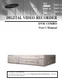
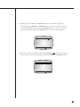
Samsung SCR-3000 Owner's manual
- Category
- Digital Video Recorders (DVR)
- Type
- Owner's manual

DIGITAL VIDEO RECORDER
DVR COMBO
User’s Manual
CLASS A (For Business)
To use this product safely, have to read “Important Safety Introductions”, and then
be well aware of the contents.

ii
DIGITAL VIDEO RECORDER
To prevent damage which may result in fire or electric shock hazard, do not expose
this appliance to rain or moisture.
This device complies with part 15 of the FCC Rules. Operation is subject to the
following two conditions.
1) This device may not cause harmful interference, and
2) This device must accept any interference that may cause undesired operation.
CAUTION
Danger of explosion if battery is incorrectly replaced.
Replace only with the same or equivalent type recommended by the manufacturer.
Dispose of used batteries according to the manufacturer’s instructions.
CAUTION
RISK OF ELECTRIC
SHOCK DO NOT OPEN
CAUTION : TO REDUCE THE RISK OF ELECTRIC SHOCK, DO
NOT REMOVE COVER (OR BACK). NO USER
SERVICEABLE PARTS INSIDE. REFER SERVICING
TO QUALIFIED SERVICE PERSONNEL.
This symbol indicates high voltage is
present inside. It is dangerous to make
any kind of contact with any inside part
of this product.
This symbol alerts you that important
literature concerning operation and
maintenance has been included with
this product.

iii
Important Safety Instructions
1. Read these instructions.
2. Keep these instructions.
3. Heed all warnings.
4. Follow all instructions.
5. Do not use this apparatus near water.
6. Clean only with dry cloth.
7. Do not block any ventilation openings. Install in accordance with the
manufacturer’s instructions.
8. Do not install near any heat sources such as radiators, heat registers, or other
apparatus (including amplifiers) that produce heat.
9. Do not defeat the safety purpose of the polarized or grounding-type plus.
A polarized plug has two blades with one wider than the other. A grounding type
plug has two blades and a third grounding prong. The wide blade or the third prong
are provided for your safety. If the provided plug does not fit into your outlet,
consult an electrician for replacement of the obsolete outlet.
10. Protect the power cord from being walked on or pinched particularly at plugs,
convenience receptacles, and the point where they exit from the apparatus.
11. Only use attachments/accessories specified by the manufacturer.
12. Use only with cart, stand, tripod, bracket, or table specified by
the manufacturer, or sold with the apparatus. When a used,
caution when moving the cart/apparatus combination to avoid
injury from tip-over.
13. Unplug this apparatus. When a cart is used, use caution when
moving the cart/apparatus combination to avoid injury from tip-over.
14. Refer all servicing to qualified service personnel. Servicing is required when the
apparatus has been damaged in any way, such as power-supply cord or plug is
damaged, liquid has been spilled or objects have fallen into the apparatus, the
apparatus has been exposed to rain or moisture, does not operate normally, or has
been dropped.

Contents
iii
v
1
2
3
1-1
1-2
1-3
1-7
1-8
1-9
2-1
2-2
2-3
2-4
3-1
3-3
4
4-1
4-6
4-7
4-10
4-14
4-15
4-17
iv
iv
Important Safety Instructions
Contents
I. Summary
1. Introduction
2. Features
3. Name and Function of Each Part
4. Introduction to the Remote Control
5. Checking the Package Contents
6. Attaching/Deta ching HDD
II. Connection with Other Devices
1. Connection to External Devices
2. Connection with Multiplexer
3.
System Connection for Alarm Recording
4. Connection with PC for Use
III. Basic Method to use
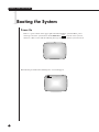
1. Booting the System
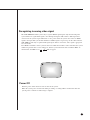
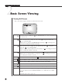
2. Basic Screen Viewing
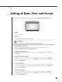
IV. DVR Menus
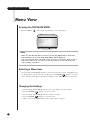
1. Menu View
2. Setting of Date, Time and Screen
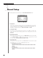
3. Record Setup
4. Alarm Record Setup
5. Reservation Timer Setup
6. System Setup
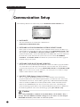
7. Communication Setup
~

v
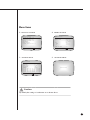
V. Viewing the VCR Menu
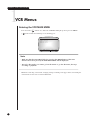
1. VCR Menus
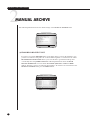
2. Manual Archive
3. Timer Archive
4. Archive Setup
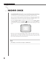
5. Archive Check
VI. Record
1. Basic Record
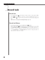
2. Record Lock
3.
Alarm Record
4. Reservation Record
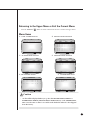
VII. Retrieval and Playback
1. Search Menus
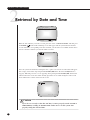
2. Retrieval by Date and Time
3.
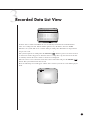
Recorded Data List View
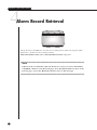
4. Alarm Record Retrieval
5. Searching Motion Detection
Recordings
6. PB CHANNEL SETUP
7. SYSTEM INDICATION
8. Basic Playback
9. VCR Playback
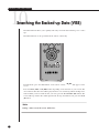
10. Searching the Backed-up Data
(VISS)
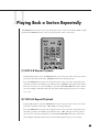
11. Playing Back a Section Repeatedly
VIII. Others
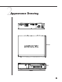
1. Product Standards
2. Appearance Drawing
Appendix
1. Check Points before Call Service
Center
2. Q & A
5
5-1
5-3
5-8
5-11
5-13
6
6-1
6-3
6-4
6-5
7
7-1
7-3
7-4
7-5
7-6
7-7
7-8
7-11
7-13
7-15
7-16
8
8-1
8-2
9
9-1
9-3

1
I. Summary

1-1
DIGITAL VIDEO RECORDER
1
Introduction
DVR COMBO is DVR system using both hard disk drive and VCR tape simultaneous-
ly. Record TV reception into hard disk drive while also recording only desired program
to VCR tape. Recorded VCR tape can be viewed with residential VCR.
DVR COMBO can play while recording sound and image simultaneously. The system
and camera can be monitored and controlled from a remote PC. Together with
Samsung Multiplexer, the system can backup only desired image per each channel.

1-2
2
Features
■ Data on your hard disk can easily be backed up onto video tapes.
● Only particular channels of the multiplexer can be backed up
● Playback of particular channels can be protected
■ Picture quality can be adjusted to 4 different levels.
● Very High, High, Normal, and Low
■ The number of recording fields per second can be adjusted.
● NTSC : 0.50 ~ 60 fields/s
● PAL : 0.50~50 fields/s
■ Recording and playback can be performed simultaneously.
■ Video and audio can be recorded simultaneously.
■ It has a timer recording function you can set just like you would your VCR.
■ Recording can be triggered by alarm sensor input.
■ It has a motion detection capability that can raise an alarm or start recording
when motion is detected.
■ It can be used in conjunction with a multiplexer. SAMSUNG SDM-160(P), 090(P)
Multiplexer SOM-080(N/P), SMO-150/210(TRN/TRP)
■ It offers various playback speeds.
● 1/5, 1/2, 1, 2, 5, 10, 20 baud rate (forward, backward)
■ It has convenient search functions.
● Date & Time Search, Record Event Search, Alarm Event Search, and Motion Event
Search
● VISS Search
■ The Remote Control allows for convenient operation.
■ Remote monitoring and controlling are possible via LAN connection.
● Network Interface : Ethernet (10 BaseT)
● Protocol : TCP/IP
● Web Server : Screen capture and remote monitoring using a viewer program installed on a PC
■ The system boots up automatically and can start recording when power is
restored following a power outage during Record mode.
■ The system can be controlled remotely through serial communication ports.
● 1 RS-232 port
● 2 RS-485 ports (up to 32 nodes)
●
Control of camera PAN/TILT/ZOOM by the LAN viewer program via RS-485
■ Recording status, remaining hard disk space, and in particular current play-
back position are displayed in bar format.
■ A removable hard drive rack allows you to easily replace hard disk drives.
■ Cameras can be controlled and channels can be selected using the Remote
Viewer program.
(Applicable only to Samsung products : SCC-641/SCC-643(N/P) Cameras, SCC-
421(N/P) Series Camera(C4201, C4203, C4301 and C4303), and SDM-160(P),
090(P) Multiplexer SOM-080(N/P), SMO-150/210(TRN/TRP)

1-3
DIGITAL VIDEO RECORDER
3
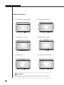
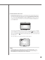
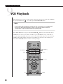
Name and Function of Each Part
Front View
POWER
ALARM LAN CHECK
REC
VCR SEARCH MENU
REC LOCK
ARCHIVE
1 2 3 4 85 97 10 11 12 13 14 15 16 17 18 6
No Name Function
STATUS LED
RECORD
POWER LED
Hard Drive
Rack
HDD LED
Remote Control
Sensor
Hard Drive
Rack Lock
REC LOCK
VCR
The removable hard drive rack into which your hard
drive could be installed.
The hard drive status indicating LED. It indicates
power status and access to the hard drive.
Receives signals from the remote control unit.
Allows you to lock the hard drive rack in place.
Indicates that power is on.
Indicates system status.
●
ALARM : Indicates alarm status.
●
LAN : Indicates when the system is connected to a
PC via LAN.
●
CHECK : Indicates any abnormal occurrence
dur ing the system operation.
●
ARCHIVE : Indicates the video tape backup.
Records live images.
Locks all keys during recording to prevent accidental
operation of the unit.
If the VCR LED is on, the system is in VCR mode
and if it is off, the system is in DVR mode.
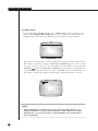
5
6
7
8
9
1
2
3
4
POWER
ALARM
LAN
CHECK
ARCHIVE
REC
REC LOCK
VCR

1-4
No Name Function
SEARCH
MENU
LEFT/REW
ENTER
DOWN/STOP
RIGHT/FF
UP/PLAY/
STILL
EJECT
VIDEO DECK
Displays a list of recorded data and allows you to easily
search through the recorded data.
Displays the menu items. Use this also to exit the
submenu and return to the menu at the next highest
level. If the VCR LED is off, the DVR MAIN
MENU will be displayed and if it is on, the VCR
MAIN MENU will be displayed.
The LEFT arrow button moves the cursor to the left.
This button also works as the REW button during play-
back. While in Pause mode, pressing this button will
make the video reverse one frame at a time.
Use this to accept the selected menu item or to accept
the changed value.
The DOWN arrow button moves the cursor down one
position or lowers a value. This button also works as the
STOP button during playback or recording.
The RIGHT arrow button moves the cursor to the right.
This button also works as the FF button during play-
back. While in Pause mode, pressing this button will
make the video advance one frame at a time.
The UP arrow button moves the cursor up one position
or raises a value. This button also works as the PLAY
button and the button to pause playback or view still
images.
Push this button to eject the video tape.
The cassette holder into which a video tape could be
inserted.
10
11
12
13
14
15
16
17
18
SEARCH
MENU

1-5
DIGITAL VIDEO RECORDER
Back View
1
2
3
4
5
P
0
W
E
R
IN
OUT
1 2 3 4 85 97 10 116
P
0
W
E
R
No Name Function
POWER
AC IN
FAN
MODE
RS485 PORT
RS232 PORT
Video In/Out
Connectors
Power On/Off switch.
The inlet for connecting the power cord.
NTSC (AC 110 ~ 240V, 60 Hz) PAL (AC 220V, 50Hz)
Fan
Dip switches for setting the system ID, serial communication,
and termination.
●
1~5 : System ID (1 : Least Significant Bit, 5 : Most
Significant Bit) (Push the dip switch up to set it to
Off (0) and push it down to set it to On (1).)
●
6 : Not Used
●
7 : Termination On/Off (Use this to set the last system
in a series of serially connected systems to ON or
OFF.) (Push the dip switch up to set it to OFF and
push it down to set it to ON.)
●
8 : Not Used
A serial port for remote control.
A serial port for remote control.
BNC style connectors for composite video input/output.
S-VIDEO input/output connectors.
6
8
7

1-6
No Name Function
Audio In/Out
LAN
External
Input/Output
Ports
RCA type audio input/output connectors.
Connector for LAN cable connection.
●
ALARM IN: In N.C. (Normally Closed) mode, the system rec
ognizes an alarm condition when a high (5V) signal is input for
longer than 0.5 second. In N.O. (Normally Open) mode, the
system recognizes an alarm condition when a low (0V) signal
is input for longer than 0.5 second.
●
ALARM RESET: If a low (0V) signal is input for longer 0.5
second, Alarm mode will be cancelled..
●
ALARM OUT: A high (5V) signal will be output during alarm
recording.
●
TRIGGER OUT: This signal is for switching the multiplexer's
recording output screen.
●
REC IN: The system begins recording if a low (0V) signal is
input for longer than 0.5 second.
●
DISK END: If DISK END MODE in the RECORD MODE
SETUP menu is set to STOP, a low (0V) signal will be output for
about 1 second when the hard drive becomes full during recording.
9
10
11

1-7
DIGITAL VIDEO RECORDER
4
Introduction to the Remote Control
Records live video
Numeric keys
Adjusts the VCR's playback screen.
Plays the tape at slow speed.
Press and hold the SLOW - button
to gradually decrease the
playback speed.
Use to check the video
tape backup.
Takes you to DVR INPUT for
selecting a DVR input signal.
Use to rewind or to sequentially view
still frames in reverse order during
DVR/VCR playback.
Stops DVR/VCR playback or
recording
Displays menu items. Use this also
to exit the submenu and return to
the menu at the next highest level.
Selects VCR mode and DVR mode.
,❷,➛,❿
directional keys
Turns OFF only the events that
currently producing buzzer output.
Takes you to VCR SPEED for
selecting a VCR recording speed.
Plays the tape at 2x speed.
p 5-13
p 4-7
p 7-13
p 7-13
p 5-11
Use to remove the video tape
Adjusts the VCR's playback
screen.
Plays the tape at slow speed.
Press and hold the SLOW + button
to gradually increase the playback
speed.
Plays back the AB section
repeatedly during DVR/VCR
playback.
DIRECT ARCHIVE
Use to view live screen during VCR
playback.
Use to fast forward or to sequentially
view still frames during DVR/VCR
playback.
Plays back DVR/VCR's recorded
data.Temporarily stops during play-
back.
Displays the recorded data
list and the system status.
Takes you to SYSTEM INDICATION
for checking the system health
status.
Use to select a menu item or to
accept the changed value.
Automatically searches the
data backed up on to the
video tape.
Locks all keys during recording to
prevent accidental operation of the
unit.
Plays the tape at slow speed.
p 7-16
p 5-8
p 7
p 7-8
p 7-15
p 7-13
p 7-13
p 7-13
p 7-13

Caution
Caution
The above items are subject to change without prior notice to improve product
performance or functionality.
1-8
5
Checking the Package Contents
When purchasing product, first remove packing and put it on a flat floor or at a place to use it.
Then, ensure all following contents are included:
◗ Main Unit
◗ User's Guide
◗ Power Cord (1)
◗ Remote Monitoring Program Installation CD-ROM
◗ Remote Control
◗ Battery (AAA size) (2)
◗ Removable Hard Drive Rack Key (2) (Including screw)
POWER
ALARM LAN CHECK
REC
VCR SEARCH MENU
REC LOCK
ARCHIVE
SCR-3000

1-9
DIGITAL VIDEO RECORDER
6
Attaching/Detaching HDD
Mounting HDD
2. Remove the hard drive rack from the
main unit by lifting up the handle on
the front of the rack and pulling
straight out.
3. Connect the removable rack's
data cable and power cord to
your hard drive.
POWER
ALARM LAN CHECK
REC
VCR SEA
REC LOCK
ARCHIVE
POWER
ALARM LAN CHECK
REC
VCR SEAR
REC LOCK
ARCHIVE
H.D.D.
Lift up
H.D.D.
H.D.D.
1. First, open the hard drive rack cover
on the front of the main unit. Next,
open the lock on the front of the rack
with the key.
4. Slide your hard drive into the
removable rack and fasten with
screws.

1-10
Caution
Caution
Be sure to lock the hard drive rack in place for normal operation of the system. Unless
the hard drive rack is locked, the system cannot recognize your hard drive.
When removing the hard drive rack, be sure to wait until your hard drive's power LED
goes off. When replacing your hard drive with another one, be sure to turn off the sys-
tem's power. If you replace your hard drive with the power on, your hard drive may
malfunction or be damaged.
If you want to use a hard drive from another machine, be sure to format it from a PC
before using it. The system may not work normally if you use it without formatting it
first. Hard disk drives recommended for use with the DVR COMBO are Samsung
Spinpoint SV0802N and SEAGATE Barracuda 7200.7 80G.
Note
Note
When installing a HDD into the hard drive rack, be sure to set the HDD as Master
mode. Otherwise, the system will not recognize the HDD. For instructions on how to
set the HDD as Master mode, please refer to the HDD's manual. For example, for a
Samsung Spinpoint V80 HDD, set the mode as follows:
H.D.D.
Lift up
5. Lift up the rack's front handle and push
the rack into the main unit. Once the
hard drive rack is fully inserted into the
main unit, lower the front handle to
secure it
6. Lock the hard drive rack with the
key, and then turn on the power.
Master Mode

II. Connection with
Other Devices
2

2-1
1
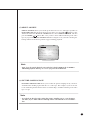
Connection to External Devices
DIGITAL VIDEO RECORDER
■ This unit can be connected to external devices such as a camera for video signal input, a
microphone for audio signal input, and an NTSC or PAL monitor for video and audio signal
output.
■ It can be connected to external devices such as an alarm according to the user’s request.
■ It can be connected to a PC through a LAN or Serial connection for remote control.
Caution
Caution
– A monitor capable of displaying an NTSC or PAL video signal must be used with
this unit. An ordinary computer monitor cannot be used.
P
0
W
E
R
IN
OUT
CAMERA
PC
LAN
VIDEO/AUDIO OUT
(NTSC/PAL MONITOR)
SIREN
MICRO PHONE

2-2
2
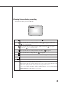
Connection with Multiplexer
(e.g. connection to SDM-160)
■ SDM-160 is a Multiplexer for NTSC, and SDM-160P is a Multiplexer for PAL.
■ Connect this unit’s video signal input jack to the video signal output jack of SDM-160 and
connect this unit’s video signal output jack to the video signal input jack of SDM-160.
■ Connect the alarm output jack (ALARM OUT) of SDM-160 to this unit’s alarm input jack
(ALARM IN), and connect the VTI jack of SDM-160 to this unit’s trigger output jack
(TRIGGER OUT).
■ Connect both GND terminals together.
■ For details on the functions of SDM-160, please refer to the user’s guide of SDM-160.
Caution
Caution
- Be sure to connect the trigger output terminal (TRIGGER OUT) of this unit to
the Multiplexer. Otherwise, a normal recording cannot be made.
(For the connection method, please refer to the user’s guide for the Multiplexer
you want to use.)
- Set up the Multiplexer so that the selection of video signals is controlled by the
Trigger Pulse in when the system’s field recording rate is set from 0.5 ~ 15 FPS
(Fields Per Second) for NTSC signals, or 0.5~12.5 FPS for PAL signals.
(For settings related to the recording field rate, please refer to "(4) PICTURE
RATE" on page 4-7.)
- Only half of a video channel may not be recorded, depending on the type of
multiplexer, when the system’s field recording rate is 30 FPS (for NTSC) or 25
FPS (for PAL). In this case, set the output mode of the multiplexer to Frame-
Mode or adjust the field recording rate of the DVR to 60 FPS (for NTSC) or 50
FPS (for PAL).
P
0
W
E
R
IN
OUT
AC IN
DVR COMBO DIGITAL VIDEO RECODER
SDM-160 DIGITAL MULTIPLEXER
MONITOR
OUT
CAMERA
1
2
3
16

2-3
DIGITAL VIDEO RECORDER
3
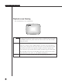
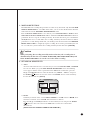
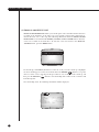
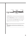
System Connection for Alarm Recording
<Rear Side Connection Terminal of DVR COMBO>
<Outside Product>
ALARM IN
ALARM RESET
ALARM OUT
GND
TRIGGER OUT
GND
REC IN
DISK END
GND
■ Alarm recording is a function for recording the input video when an alarm signal is input
while a device with alarm output is connected to this unit.
■ Connect to the corresponding terminals, as the numbers may be different for external
devices.
■ For external devices, if the alarm input (ALARM INPUT) and alarm cancel (ALARM
CANCEL) are not available, you can leave them unconnected.
GND
TRIGGER IN
ALARM IN
ALARM CANCEL
ALARM OUT
1
1
2
3
4
5
6
7
8
9
1
2
3
4
5
2 3 4 5
6
7 8 9 1 2 3 4 5
Page is loading ...
Page is loading ...
Page is loading ...
Page is loading ...
Page is loading ...
Page is loading ...
Page is loading ...
Page is loading ...
Page is loading ...
Page is loading ...
Page is loading ...
Page is loading ...
Page is loading ...
Page is loading ...
Page is loading ...
Page is loading ...
Page is loading ...
Page is loading ...
Page is loading ...
Page is loading ...
Page is loading ...
Page is loading ...
Page is loading ...
Page is loading ...
Page is loading ...
Page is loading ...
Page is loading ...
Page is loading ...
Page is loading ...
Page is loading ...
Page is loading ...
Page is loading ...
Page is loading ...
Page is loading ...
Page is loading ...
Page is loading ...
Page is loading ...
Page is loading ...
Page is loading ...
Page is loading ...
Page is loading ...
Page is loading ...
Page is loading ...
Page is loading ...
Page is loading ...
Page is loading ...
Page is loading ...
Page is loading ...
Page is loading ...
Page is loading ...
Page is loading ...
Page is loading ...
Page is loading ...
Page is loading ...
Page is loading ...
Page is loading ...
Page is loading ...
Page is loading ...
Page is loading ...
Page is loading ...
Page is loading ...
Page is loading ...
Page is loading ...
Page is loading ...
Page is loading ...
Page is loading ...
Page is loading ...
Page is loading ...
Page is loading ...
Page is loading ...
Page is loading ...
Page is loading ...
Page is loading ...
Page is loading ...
-
 1
1
-
 2
2
-
 3
3
-
 4
4
-
 5
5
-
 6
6
-
 7
7
-
 8
8
-
 9
9
-
 10
10
-
 11
11
-
 12
12
-
 13
13
-
 14
14
-
 15
15
-
 16
16
-
 17
17
-
 18
18
-
 19
19
-
 20
20
-
 21
21
-
 22
22
-
 23
23
-
 24
24
-
 25
25
-
 26
26
-
 27
27
-
 28
28
-
 29
29
-
 30
30
-
 31
31
-
 32
32
-
 33
33
-
 34
34
-
 35
35
-
 36
36
-
 37
37
-
 38
38
-
 39
39
-
 40
40
-
 41
41
-
 42
42
-
 43
43
-
 44
44
-
 45
45
-
 46
46
-
 47
47
-
 48
48
-
 49
49
-
 50
50
-
 51
51
-
 52
52
-
 53
53
-
 54
54
-
 55
55
-
 56
56
-
 57
57
-
 58
58
-
 59
59
-
 60
60
-
 61
61
-
 62
62
-
 63
63
-
 64
64
-
 65
65
-
 66
66
-
 67
67
-
 68
68
-
 69
69
-
 70
70
-
 71
71
-
 72
72
-
 73
73
-
 74
74
-
 75
75
-
 76
76
-
 77
77
-
 78
78
-
 79
79
-
 80
80
-
 81
81
-
 82
82
-
 83
83
-
 84
84
-
 85
85
-
 86
86
-
 87
87
-
 88
88
-
 89
89
-
 90
90
-
 91
91
-
 92
92
-
 93
93
-
 94
94


Samsung SCR-3000 Owner's manual
- Category
- Digital Video Recorders (DVR)
- Type
- Owner's manual
Ask a question and I''ll find the answer in the document
Finding information in a document is now easier with AI
Related papers
-
Samsung SCR-3000P User manual
-
-
-
-
-
-
-
-
-
Other documents
-
 Okina USA VA122BNC Owner's manual
-
Maxtor Digital Video Recorder CBC V 0.4 User manual
-
 Mitsubishi Electronics DX-NT400E User manual
-
CBC V 0.1 User manual
-
 Mitsubishi Electronics DX-TL1600U User manual
-
Mitsubishi Electric DX-TL5000E User manual
-
Sanyo DSR-3000P Manual Manual
-
RS SSD01CA User manual
-
-
 Santec SDVR-1/TX-S User manual


