Page is loading ...

FPI FIREPLACE PRODUCTS INTERNATIONAL LTD. 6988 Venture St., Delta, BC Canada, V4G 1H4
919-372b
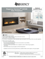
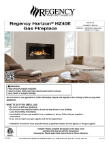
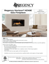
Regency Horizon
®
HZ54E
Gas Fireplace
06.13.17
Owners &
Installation Manual
www.regency-re.com
Tested by:
Installer: Please complete the details on the back cover
and leave this manual with the homeowner.
Homeowner: Please keep these instructions for future reference.
MODELS: HZ54E-NG10 Natural Gas
HZ54E-LP10 Propane
Horizon HZ54E Product Video
- Do not store or use gasoline or other flammable vapors and liquids in the vicinity of this or any other
appliance.
- WHAT TO DO IF YOU SMELL GAS
•
Do not try to light any appliance.
• Do not touch any electrical switch: do not use any phone in your building.
Leave the building immediately.
• Immediately call your gas supplier from a neighbour's phone. Follow the gas supplier's
instructions.
• If you cannot reach your gas supplier, call the fire department.
- Installation and service must be performed by a qualified installer, service agency or the gas supplier.
WARNING
FIRE OR EXPLOSION HAZARD
Failure to follow safety warnings exactly could result in serious
injury, death, or property damage.

2 | Regency Horizon
®
HZ54E-10 Gas Fireplace
|
2
To the New Owner:
Congratulations!
You are the owner of a state-of-the-art Gas Fireplace by REGENCY
®
. The HZ54E has been designed to provide
you with all the warmth and charm of a wood fireplace at the flick of a switch. The model HZ54E has been
approved by Warnock Hersey/Intertek for both safety and efficiency. As it also bears our own mark, it promises
to provide you with economy, comfort and security for many trouble free years to follow. Please take a moment
now to acquaint yourself with these instructions and the many features of your Regency
®
Fireplace.

Regency Horizon
®
HZ54E-10 Gas Fireplace | 3
|
3
This appliance can only be used with the type of gas indicated on the rating plate.
This appliance is not convertible for use with other gases.
This appliance may be installed as an OEM installation in a manufactured home (USA only) or mobile home and must be
installed in accordance with the manufacturer's instruction and the Manufactured Home Construction and Safety Standard,
Title 24 CFR, Part 3280, in the Untied States, or the Standard for Installation in Mobile Homes, CAN/CSA Z240 MH, in
Canada.
MANUFACTURED MOBILE HOME REQUIREMENTS
INFORMATION FOR MOBILE/MANUFACTURED HOMES AFTER FIRST SALE
This Regency
®
product has been tested and listed by Warnock Hersey/Intertek as a Direct Vent Wall Furnace to the following
standards: VENTED GAS FIREPLACE HEATERS ANSI Z21.88-2014 / CSA 2.33-2014 and GAS-FIRED APPLIANCES FOR
USE AT HIGH ALTITUDES CAN / CGA 2.17-M91.
This appliance may only be installed in an aftermarket permanently located, manufactured (U.S.A only) or mobile home,
where not prohibited by local codes.
This Direct Vent System Appliance must be installed in accordance with the manufacturer's installation instructions and the
Manufactured Home Construction and Safety Standard, Title 24 CFR, Part 3280, or the current Standard of Fire Safety Criteria
for Manufactured Home Installations, Sites, and Communities ANSI/NFPA 501A, and with CAN/CSA Z240-MH Mobile Home
Standard in Canada.
This appliance installation must comply with the manufacturer's installation instructions and local codes, if any. In the absence
of local codes follow the current National Fuel Gas Code, ANSI Z223.1 and the current National Electrical Code ANSI/NFPA
70 in the U.S.A., and the current CAN/CGA B149 Gas Installation Code and the current Canadian Electrical Code CSA C22.1
in Canada.
This appliance comes equipped with a dedicated #8 Ground Lug for attachment of the ground wire to the steel chassis as
applicable to local codes.
The appliance, when installed, must be electrically grounded in accordance with local codes or, in the absence of local codes,
with the National Electrical Code, ANSI/NFPA 70, or the Canadian Electrical Code, CSA C22.1.
Ensure that structural members are not cut or weakened during installation.
Regency Horizon
Gas Inserts Benets Video
Horizon HZ54 Product Video

4 | Regency Horizon
®
HZ54E-10 Gas Fireplace
|
4
table of contents
Copy of Safety Decal .....................................................5
MA Code - CO Detector ................................................6
Dimensions
Unit Dimensions ............................................................7
Faceplate & Door frame overlay Dimensions ................7
Installation
Important Message ......................................................8
Before You Start .............................................................8
General Safety Information ............................................8
Installation Checklist ......................................................9
Locating Your Gas Fireplace ..........................................9
Heatwave Duct System .................................................9
Heat Release kit ............................................................9
Clearances ..................................................................10
Non-Combustible Requirements..................................10
Non combustible facing board .....................................11
Non-combustible facing installation ............................11
Mantel Clearances .......................................................12
Mantel Leg Clearances ................................................12
Framing & Finishing .....................................................13
Unit Assembly Prior To Installation ..............................14
Standoff Assembly ...............................................14
Nailing Strips........................................................14
Venting Introduction .....................................................14
Framing Dimensions ....................................................15
Optional Framing Kit ....................................................16
wall mount On / Off Switch / receiver installation.........17
Vent Restrictor Position ...............................................18
Exterior Vent Termination Requirements .....................19
Venting Arrangements ................................................20
Horizontal Termination (Flex) ...............................20
Rigid Pipe Venting Systems .........................................21
Basic Horizontal & Vertical Terminations .............21
5” x 8” Rigid Pipe Cross Reference Chart ...................22
Venting Arrangements ................................................24
Allowable Horizontal Terminations for HZ54E-ng . 24
Venting Arrangements ................................................24
Allowable Horizontal Terminations for HZ54E-lp . . 24
Venting Arrangements ................................................27
Allowable Vertical Terminations for HZ54E-ng .....27
Venting Arrangements ................................................28
Allowable Vertical Terminations for HZ54E-lp ......28
Unit Installation with Horizontal Termination ................29
Unit Installation with Vertical Termination ....................30
Unit Installation ............................................................31
Horizontal Termination with Flex Vent System .............31
High Elevation ..............................................................32
Gas Line Installation ....................................................32
Pilot Adjustment ...........................................................32
Gas Pipe Pressure Testing ..........................................32
885 S.I.T. Valve Description .........................................32
Valve cover removal .....................................................33
Aeration Adjustment ....................................................34
Wiring Diagram ............................................................35
Optional Wall Thermostat Installation ..........................36
Optional Reflective Panel Installation ..........................37
Glass Crystals or optional stones ................................38
Installation On Burner ..................................................38
Optional Pebbles / glass crystal Installation ................38
Optional driftwood Log set Installation .........................39
Faceplate & Door frame overlay Installation ................41
Wiring diagram with optional fan .................................47
Operating Instructions
Operating Instructions .................................................48
First Fire ......................................................................48
Normal Operating Sounds of Gas Appliances .............48
Lighting Procedure ......................................................49
Shutdown Procedure ...................................................49
Copy of Lighting Plate Instructions ..............................50
Maintenance
Maintenance Instructions ............................................51
General Vent Maintenance ..........................................51
Glass Gasket ...............................................................51
Glass Door ...................................................................51
Glass Replacement .....................................................51
Glass Door Removal....................................................52
safety screen removal / installation ..............................53
Valve Tray Replacement ..............................................54
HZ54E-NG unit ............................................................55
HZ54E-LP unit .............................................................56
Parts
Main Assembly ............................................................57
Accessories .................................................................59
Warranty
The Warranty: Limited Lifetime ...................................60
ALL PICTURES / DIAGRAMS SHOWN THROUGHOUT THIS MANUAL ARE FOR ILLUSTRATION PURPOSES ONLY.
ACTUAL PRODUCT MAY VARY DUE TO PRODUCT ENHANCEMENTS.

Regency Horizon
®
HZ54E-10 Gas Fireplace | 5
|
5
safety decal
COPY OF SAFETY DECAL
For the State of Massachusetts, installation
and repair must be done by a plumber or
Massachusetts.
-
For the State of Massachusetts, the appli-
t-handle type valve.
The State of Massachusetts requires the
the gas appliance is installed.
DO NOT REMOVE THIS LABEL /
NE PAS ENLEVER CETTE ÉTIQUETTE
363
363
D OOR SEAL: Please
check that the door is
properly sealed
FPI Fireplace Products International Ltd. Delta, BC, Canada
Minimum Clearances to Combustibles /
Degagement Minimum De Materiaux Combustibles
Serial No./ No de s rieé
919-373
MAY BE INSTALLED IN MANUFACTURED (MOBILE) HOMES AFTER FIRST SALE.
.
NOT FOR USE WITH SOLID FUEL / NE PAS UTILISER AVEC COMBUSTIBLE SOLIDEUN
Made in Canada/ Fabriqu au Canadaé
Duplicate S/N
(See Instruction Manual for
detailed instructions)
APPAREIL FONCTIONNANT AU GAZ PROPANE
Modleè HZ54E-LP10
PROPANE GAS: Model HZ54E-LP10
APPAREIL FONCTIONNANT AU GAZ NATUREL
Modleè HZ54E-NG10
Pression d'alimentation minimum
Pression manifold - basse
Pression manifold maximum
Taille de l’orifice
D bit alorifique minimumceté
D bit alorifique maximum seloncé
l'altitude
Pression d'alimentation minimum
Pression manifold - basse
Pression manifold max.
Taille de l’orifice
Dbit alorifique minimumceté
Dbit alorifique maximum seloncé
l'altitude
D
E
F
A
B
C
Side Walls/Murs latéraux
A4” (102mm)
Ceiling/Plafond
B 40-7/8” (1038mm)
Min. Mantel Height/Hteur manteau min.
C 20" (508mm)
Max. Mantel Depth/Prof. manteau max.
D13” (330mm)
Alcove Width/Largeur alcôve
E 83" (2108mm)
Alcove Depth/Prof. alcôve
F 36" (914mm)
This appliance must be installed in accordance with local codes, if any; if none, follow the National Fuel Gas Code, ANSI Z223.1, or Natural Gas and Propane Installation Code, CSA B149.1.
This appliance must be installed in accordance with the Standard CAN/CSA Z240 MH, Mobile Housing, in Canada, or with the Manufactured Home Construction and Safety Standard,Title 24 CFR, Part 3280, in
the United States, or when such a standard is not applicable,ANSI/NCSBCSA225.1/NFPA501A, Manufactured Home Installations Standard orANSIA119.2 ou NFPA501C Standard for Recreational Vehicles
This appliance is only for use with the type of gas indicated on the rating plate and may be installed in an aftermarket, permanently located, manufactured (mobile) home where not prohibited by local codes. See
owner's manual for details.
Installer l'appareil selon les codes ou règlements locaux, ou, en l'absence de tels règlements, selon les codes d'installation ANSI Z223.1, National Fuel Gas Code ou CSA-B149.1 en vigueur.
Installer l'appareil selon la norme CAN/CSA-Z240, Série MM, Maison mobiles ou CAN/CSA-Z240 VC, Véhicules de camping, ou la norme 24 CFR Part 3280, Manufactured Home Construction and Safety
Standard. Si ces normes ne sont pas pertinentes, utilisez la norme ANSI/NCSBCS A225.1/NFPA 501A, Manufactured Home Installations Standard, ou ANSI A119.2 ou NFPA501C Standard for Recreational
Vehicles.
Cet appareil doit être utili uniquement avec le type de gaz indiqué sur la plaque signalétique. peut être installé dans une maison préfabriquée ou mobile (É.-U. seulement) installée à demeure si lessé Il
règlements locaux le permettent. Voir ldel'utilisateur pour plus de renseignements.e guide
This vented gas fireplace heater is not for use with air filters. Ne pas utiliser de filtre à air avec ce foyer au gaz à évacuation.
For Use Only with Barrier (Part # 478-013) Follow installation instructions. Utiliser uniquement avec un écran de protection ( n°478-013). Suivre les consignes d'installation.
FOR USE WITH GLASS DOORS CERTIFIED WITH THEAPPLIANCE ONLY À UTILISER VITRÉESUNIQUEMENTAVEC LES PORTES CERTIFIÉESAVEC L'APPAREIL
Min. Supply Pressure 12“WC (2.98 kpa)
Low Setting Man. Pressure 6.4"WC (1.59 kpa)
Max. Manifold Pressure 10"WC (2.49 kpa)
Orifice Size #49 DMS
Minimum Input 30,000Btu/ (8.79 kW)
Maximum Input 37,000Btu/h (10.84 kW)
0-4500 ft/pi (0-1372 m)
Altitude
Part #: 919-373
Colour: Black on grey except what is indicated as being printed red.
Size: 9.114”W x 6.017”H (File at 100%)
Material: 2 ml silver matt polyester (DPM SMS)
May 22/14: Created decal
May27/14: Updated model name to -10
Printer: Continue number sequence from 919-268 - do not restart at 0
Min. Supply Pressure 5“ WC (1.25 kpa)
Low Setting Man. Pressure 1.6"WC (0.40 kpa)
Max. Manifold Pressure 3.5"WC (0.87 kpa)
Orifice Size #30DMS
Minimum Input 29,000Btu/h (8.50 kW)
Maximum Input 41,500 Btu/h (12.16 kW)
0-4500 ft/pi (0-1372 m)
Altitude
NATURAL GAS: Model HZ54E-NG10
4001172
Listed: VENTED GAS FIREPLACE HEATER / FOYER AU GAZ À ÉVACUATION
CANADA and U.S.A.Certified for/Certifi e pour:é
Tested to: CAN/CGA-2.17-M91(R2009)
ANSI Z21.88-2014Conforms to:
14CSA 2.33-20Certified to:
This is a copy of the label that accompanies each
Fireplace. We have printed a copy of the contents
NOTE: Regency
®
units are constantly being

6 | Regency Horizon
®
HZ54E-10 Gas Fireplace
|
6
requirements
5.08: Modifications to NFPA-54, Chapter 10
(2) Revise 10.8.3 by adding the following additional requirements:
(a) For all side wall horizontally vented gas fueled equipment installed in every dwelling, building or structure used in whole or in part for
residential purposes, including those owned or operated by the Commonwealth and where the side wall exhaust vent termination is less than
seven (7) feet above finished grade in the area of the venting, including but not limited to decks and porches, the following requirements shall
be satisfied:
1. INSTALLATION OF CARBON MONOXIDE DETECTORS. At the time of installation of the side wall horizontal vented gas fueled
equipment, the installing plumber or gasfitter shall observe that a hard wired carbon monoxide detector with an alarm and battery back-up is
installed on the floor level where the gas equipment is to be installed. In addition, the installing plumber or gasfitter shall observe that a battery
operated or hard wired carbon monoxide detector with an alarm is installed on each additional level of the dwelling, building or structure
served by the side wall horizontal vented gas fueled equipment. It shall be the responsibility of the property owner to secure the services of
qualified licensed professionals for the installation of hard wired carbon monoxide detectors
a. In the event that the side wall horizontally vented gas fueled equipment is installed in a crawl space or an attic, the hard wired carbon
monoxide detector with alarm and battery back-up may be installed on the next adjacent floor level.
b. In the event that the requirements of this subdivision can not be met at the time of completion of installation, the owner shall have a period of
thirty (30) days to comply with the above requirements; provided, however, that during said thirty (30) day period, a battery operated carbon
monoxide detector with an alarm shall be installed.
2. APPROVED CARBON MONOXIDE DETECTORS. Each carbon monoxide detector as required in accordance with the above provisions
shall comply with NFPA 720 and be ANSI/UL 2034 listed and IAS certified.
3. SIGNAGE. A metal or plastic identification plate shall be permanently mounted to the exterior of the building at a minimum height of eight
(8) feet above grade directly in line with the exhaust vent terminal for the horizontally vented gas fueled heating appliance or equipment. The
sign shall read, in print size no less than one-half (1/2) inch in size, "GAS VENT DIRECTLY BELOW. KEEP CLEAR OF ALL
OBSTRUCTIONS".
4. INSPECTION. The state or local gas inspector of the side wall horizontally vented gas fueled equipment shall not approve the installation
unless, upon inspection, the inspector observes carbon monoxide detectors and signage installed in accordance with the provisions of 248 CMR
5.08(2)(a)1 through 4.
(b) EXEMPTIONS: The following equipment is exempt from 248 CMR 5.08(2)(a)1 through 4:
1. The equipment listed in Chapter 10 entitled "Equipment Not Required To Be Vented" in the most current edition of NFPA 54 as adopted by
the Board; and
2. Product Approved side wall horizontally vented gas fueled equipment installed in a room or structure separate from the dwelling, building or
structure used in whole or in part for residential purposes.
(c) MANUFACTURER REQUIREMENTS - GAS EQUIPMENT VENTING SYSTEM PROVIDED. When the manufacturer of Product
Approved side wall horizontally vented gas equipment provides a venting system design or venting system components with the equipment, the
instructions provided by the manufacturer for installation of the equipment and the venting system shall include:
1. Detailed instructions for the installation of the venting system design or the venting system components; and
2. A complete parts list for the venting system design or venting system.
(d) MANUFACTURER REQUIREMENTS - GAS EQUIPMENT VENTING SYSTEM NOT PROVIDED. When the manufacturer of a
Product Approved side wall horizontally vented gas fueled equipment does not provide the parts for venting the flue gases, but identifies
"special venting systems", the following requirements shall be satisfied by the manufacturer:
1. The referenced "special venting system" instructions shall be included with the appliance or equipment installation instructions; and
2. The "special venting systems" shall be Product Approved by the Board, and the instructions for that system shall include a parts list and
detailed installation instructions.
(e) A copy of all installation instructions for all Product Approved side wall horizontally vented gas fueled equipment, all venting instructions,
all parts lists for venting instructions, and/or all venting design instructions shall remain with the appliance or equipment at the completion of
the installation.
MA Code - CO Detector
(for the State of Massachusetts only)

Regency Horizon
®
HZ54E-10 Gas Fireplace | 7
|
7
dimensions
FACEPLATE & DOOR FRAME OVERLAY DIMENSIONS
UNIT DIMENSIONS

8 | Regency Horizon
®
HZ54E-10 Gas Fireplace
|
8
installation
4) This appliance must be connected to the speci-
5) -
age and any signs of deterioration.
6)
7)
be replaced prior to operating the appliance.
8)
9) Wear gloves and safety glasses for protection
10)
11) Under no circumstances should this appliance
servicing should be replaced prior to operating
this appliance.
12) Installation and any repairs to this appliance
should be done by an authorized service per-
it a practice to have all of your gas appliances
13)
14) Under no circumstances should any solid fuels
this appliance.
15)
California to cause cancer, birth defects or
other reproductive harm.
IMPORTANT MESSAGE
SAVE THESE
INSTRUCTIONS
need for a permit prior to starting the installation.
It is the responsibility of the installer to ensure
manufacturers instructions and all applicable codes.
BEFORE YOU START
Safe installation and operation of this appliance
GENERAL SAFETY
INFORMATION
1) -
2) -
C22.1 Canadian Electrical Code.
3) See general construction and assembly in-
structions. The appliance and vent should be
enclosed.
CHILDREN AND ADULTS SHOULD BE
ALERTED TO THE HAZARDS OF HIGH
SURFACE TEMPERATURES, ESPE-
CIALLY THE FIREPLACE GLASS, AND
SHOULD STAY AWAY TO AVOID BURNS
OR CLOTHING IGNITION.
INSTALLATION AND REPAIR SHOULD
BE DONE BY AN AUTHORIZED
SERVICE PERSON. THE APPLIANCE
SHOULD BE INSPECTED BEFORE
USE AND AT LEAST ANNUALLY BY A
PROFESSIONAL SERVICE PERSON.
MORE FREQUENT CLEANING MAY
BE REQUIRED DUE TO EXCESSIVE
LINT FROM CARPETING, BEDDING
MATERIAL, ETC. IT IS IMPERATIVE THAT
CONTROL COMPARTMENTS, BURNERS
AND CIRCULATING AIR PASSAGEWAYS
OF THE APPLIANCE BE KEPT CLEAN.
DUE TO HIGH TEMPERATURES, THE
APPLIANCE SHOULD BE LOCATED
OUT OF TRAFFIC AND AWAY FROM
FURNITURE AND DRAPERIES.
WARNING: FAILURE TO INSTALL THIS
APPLIANCE CORRECTLY WILL VOID
YOUR WARRANTY AND MAY CAUSE A
SERIOUS HOUSE FIRE.
CLOTHING OR OTHER FLAMMABLE
MATERIAL SHOULD NOT BE PLACED
ON OR NEAR THE APPLIANCE.
YOUNG CHILDREN SHOULD BE CARE-
FULLY SUPERVISED WHEN THEY ARE
IN THE SAME AREA AS THE APPLI-
ANCE. TODDLERS, YOUNG CHILDREN
AND OTHERS MAY BE SUSCEPTIBLE
TO ACCIDENTAL CONTACT BURNS. A
PHYSICAL BARRIERS IS RECOMMEND-
ED IF THERE ARE AT RISK INDIVIDUAL
IN THE HOUSE. TO RESTRICT ACCESS
TO A FIREPLACE OR STOVE, INSTALL
AN ADJUSTABLE SAFETY GATE TO
KEEP TODDLERS, YOUNG CHILDREN
AND OTHER AT RISK INDIVIDUALS OUT
OF THE ROOM AND AWAY FROM HOT
SURFACES.
A BARRIER DESIGNED TO REDUCE
THE RISK OF BURNS FROM THE HOT
VIEWING GLASS IS PROVIDED WITH
THIS APPLIANCE AND SHALL BE
INSTALLED FOR THE PROTECTION
OF CHILDREN AND OTHER AT-RISK
INDIVIDUALS
IF THE BARRIER BECOMES DAMAGED,
THE BARRIER SHALL BE REPLACED
WITH THE MANUFACTURER'S BARRIER
FOR THIS APPLIANCE.
ANY SAFETY SCREEN, GUARD, OR
BARRIER REMOVED FOR SERVICING
AN APPLIANCE MUST BE REPLACED
PRIOR TO OPERATING THE APPLIANCE.

Regency Horizon
®
HZ54E-10 Gas Fireplace | 9
|
9
installation
This includes:
1)
, after burning appliance for
15 minutes.
2) If required, adjusting the primary air to ensure
unit to burn for 15-20 min. to stabilize.
CAUTION: Any alteration to the product that
causes sooting or carboning that results in dam-
age is not the responsibility of the manufacturer.
LOCATING YOUR
GAS FIREPLACE
A) Flat on Wall
B) Flat on Wall Corner
C)
D) Corner
Diagram 1
1)
ensure that the clearances are met.
2)
-
plication. The appliance must be installed on
and depth of the appliance.
3)
installed in a recessed position or framed out
INSTALLATION CHECKLIST
1)
2)
3) Slide unit into place.
4)
5)
6)
7). See remote control instructions for operation
of this device.
8)
9)
10) Install standard and optional features. Refer to
Stones
11)
correctly and operation fully explained to
customer.
4)
installations using the standard Remote
before installation.
5)
is approved for alcove installations, see
6) We recommend that you plan your installation
installing this appliance. Have an authorized
before installation.
Note: For vent terminations refer to "Exterior
Vent Termination Locations" section.
HEATWAVE
DUCT SYSTEM
OPTIONAL KIT #946-556
The HeatWave
room or other rooms in your home.
Please Note:-
OPTIONAL
HEAT RELEASE KIT
#946-570
or right side.
The HeatWave
the HeatWave manual for details.

10 | Regency Horizon
®
HZ54E-10 Gas Fireplace
|
10
installation
Caution Requirements
NOT be
recessed into combustible construction.
WARNING
Fire hazard is an extreme risk if these clearances (air space) to combustible materials
are not adhered to. It is of greatest importance that this replace and vent system be
installed only in accordance with these instructions.
CLEARANCES
The clearances listed below are Minimum distances unless otherwise stated:
A major cause of chimney related res is failure to maintain required clearances (air space) to combustible materials. It is of the greatest importance
that this replace and vent system be installed only in accordance with these instructions.
F
B
E
D
A
Installed Close
to Floor
G
Clearance: Dimension Measured From:
A: Mantel Height (min.)
B: Sidewall (on one side)
C: Ceiling
(room and/or alcove)
D: Mantel Depth (max.)
E: Alcove Width
F: Alcove Depth
G: To Floor
Note
F
B
C
Installed Close
to Ceiling
Flue Clearances to Combustibles
Horizontal - Top
Horiztonal - Side
Horiztonal - Bottom
42-3/8”
(
1079mm)
3-7/8"
(
99mm)
5-1/2”
(140mm)
22-1/2”
(572
mm)
19-7/8"
(505mm)
22-5/8
”
52-7/8”
60-1/2"(1537mm)
Non-combustibl
e
Material
Non-combustible Material
Non-combustible
Material
Non-combustible Material
MetalStud(header)
Wood Stud
Wo
od Stud
NON-COMBUSTIBLE REQUIREMENTS
The HeatWave
HeatWave and Heat Release manual
for details.
Heat Release Kit

Regency Horizon
®
HZ54E-10 Gas Fireplace | 11
|
11
installation
If finishing the wall above the unit with paint -
the non-combustible board (shipped separately
from the unit) should be installed. Facing board
must be ordered when ordering the unit.
Calcium silicate board is a high - grade material
with cement, quartz, natural and selected
minerals as the main raw materials. It is widely
used for partitions and ceilings in buildings.
It is fire proof and earthquake proof.
If finishing the wall above the unit with materials
such as tile, brick, marble, etc. non-combustible
board available from the building supply store
can be used.
Note: Calcium Silicate is 1/2" thick.
Caution: This non-combustible board can be damaged if
dropped or struck. Handle with care.
4"
(102mm)
22-3/8”
(568mm)
20"
(508mm)
21-3/4”
52-5/8”
61-1/2" (1537mm)
Non-combustible
Facing Board
Non-combustible Facing Board
Non-combustible Facing Board
Metal Stud (header)
Wood
Stud
Wood Stud
Non-combustible Facing Board
61-1/2" (1537mm)
5-5/8”
(
143mm)
NON COMBUSTIBLE FACING BOARD
All four pieces (top, 2 sides, bottom) are now supplied (shipped separately) to meet the non combustible requirements. (Previously only the top was
supplied).
NON-COMBUSTIBLE FACING INSTALLATION
Non-combustible board
Non-combustible board-faces and edges
MUST BE PRIMED.
Non-combustible board
Caution: The non-combustible board can be damaged if dropped or
struck. Handle with care.
1) Using drywall screws - secure non combustible material
around unit, framing and top nailing strip every 6 inches.
Important Note: To avoid cracking the board - pre-drill holes prior to
securing to unit/ framing.
2) Wipe any debris/dust from the non combustible
material and drywall.
3) Prior to securing it is mandatory to prime the facing and edges using a
quality primer. This will ensure proper adhesion of both the tape, mud
and paint. The supplied board is very porous.
Failure to follow this procedure will result in cracked seams.
4) Tape the seams using a mesh type tape.
5) Mud seams as normal. We recommend using a
product called Durabond high strength compound - for the first coat.
This product can be found at any hardware store.
Mud must be cured as per manufacturer’s recommendations.
6) Prime wall for a second time for proper adhesion of paint
7) Paint walls using a high quality paint which will withstand
the high temperatures being emitted from this appliance.
IMPORTANT
Regency Fireplace Products are designed, produced, tested and certified to the highest industry standards.
The finishing of the walls surrounding your Regency Horizon Fireplace is as critical as the installation itself.
The temperatures around linear gas fireplaces are typically higher than would be acceptable for combustible materials. Your Regency Horizon Fireplace is no exception to this
rule. Therefore, the units are specified with non-combustible required materials to specific dimensions above and around the units. This is due to these areas reaching higher
temperature levels than required/acceptable for a combustible material. To obtain the best, most durable finish around your fireplace, this calls for a high level of care and attention
to the preparation and finish around this appliance, using only the highest quality materials, able to withstand the temperatures produced.
By following the installation instructions in the manual exactly, you will increase your chances of a damage free finish.
While every precaution is taken in providing the recommendations on preparation and finish, given the variations in paint quality, with temperature limits and workmanship in
application, Regency is unable to guarantee the life of the joint compounds, paint or any other finish materials or workmanship applied to or used in any application surrounding
the fireplace. This includes framing as well as finishing.
Over time natural convection from any fireplace can cause discoloration in the area directly above the appliance. Lower quality paints, under-prepared finishes, poor applications,
and any framing discrepancies or in the installation can cause this discoloration process to be expedited.
Discoloration is not the responsibility of Regency Fireplace Products. This is outwith the control of Regency Fireplace Products Ltd., therefore not covered under any part of the
warranty policy.
While discoloration is not the responsibility of Regency Fireplace Products, we believe careful attention to the recommendations provided here will result in an aesthetically
pleasing result free of issues outlined above.

12 | Regency Horizon
®
HZ54E-10 Gas Fireplace
|
12
installation
MANTEL CLEARANCES
Due to the extreme heat this replace emits, the mantel clearances are critical.
the diagram on the right.
Note: Ensure the paint that is used on the mantel
and the facing is "High Quality" or the paint
may discolour.
MANTEL LEG CLEARANCES
4"
Allowable mantel
leg projection
5-1/2” (140mm)
8” (203mm)
11” (279mm)
1.5" (38mm)
MANTEL LEG
4”(102mm)
Non-Combustible
7”
Note: A non-combustible mantel may be
installed at a lower height if the framing
is made of metal studs covered with a
non-combustible board.
Drywall
2
0
12
6
4
810
Top of
Fireplace
Opening
13" (330mm)
3 ½" (89mm)
Metal Stud
(On Edge)
0
10
20
14
Non-combustible facing.
Must be supported
using steel stud or
the framing kit
To Unit
Base Legs
1" (25mm)
30”
20”
21”
28-1/8”
Combustible Material
30

Regency Horizon
®
HZ54E-10 Gas Fireplace | 13
|
13
installation
FRAMING & FINISHING
1)
IMPORTANT: Header must be metal stud.
Note: When constructing the framed opening, please ensure there is access to install the gas lines when the unit is installed.
2)
(Do not insulate the replace itself.)
WARNING: Failure to insulate and add vapor barriers to the inside of the exterior wall will result in operational and performance problems in-
cluding, but not limited to: excessive condensation on glass doors, poor ame package, carbon, blue ames etc. These are not product related
issues.
3)
4)
must be adhered to, this is to ensure removal of the faceplate.
and for the safe operation of this appliance.
52-7/8”
22-5/8”
Unit shown without faceplate for Illustrative purposes only
Important:
Examples:
Note:
-

14 | Regency Horizon
®
HZ54E-10 Gas Fireplace
|
14
installation
Nailing Strips
Shipping brackets -
remove after shipped.
NAILING STRIPS
The nailing strips come attached to the unit. There is 1 plate on each side,
that can be folded out as required. The side nailing strips are secured to the
framing.
UNIT ASSEMBLY PRIOR TO
INSTALLATION
correctly positioned and attached to the unit before sliding the unit into position.
STANDOFF ASSEMBLY
folded into shape and attached - see diagram 1.
1)
2)
on the unit line up.
VENTING INTRODUCTION
up the chimney.
Note: These ue pipes must not be connected to any other appliance.
The gas appliance and vent system must be vented directly to the outside of
the building, and never be attached to a chimney serving a separate solid fuel
separate vent system. Common vent systems are prohibited.
IMPORTANT NOTE
Remove screws to
release standos
Diagram 1
Diagram 2
Diagram 3

Regency Horizon
®
HZ54E-10 Gas Fireplace | 15
|
15
installation
Framing
Dimensions
Description HZ54E
Framing Height
B Framing Width
C
* *
Minimum Height to Combustibles
E
F Corner Facing Wall Width
H
I
J
*
Important:
using non combustible materials.
FRAMING DIMENSIONS
NOTE: If not purchasing the optional steel stud kit - adhere to the same framing if purchasing steel studs elsewhere. The use of the optional kit is highly
recommended as it was designed specifically for the product to facilitate ease of installation.

16 | Regency Horizon
®
HZ54E-10 Gas Fireplace
|
16
installation
OPTIONAL FRAMING KIT
919-441
09.15.14
63"
50-1/4"
1. Construct the wood framing, ensure the inside dimensions are
63" W x 50-1/*4" H
2. Bend both nailing strips from the sides of the appliance until positioned
as shown below.
Determine the overall combined thickness of the non-combustible board
+nished material being used. The nailing strips can be adjusted 3-1/8".
3. Adjust nailing strips by loosening 2 screws on each nailing strip - adjust
and retighten the screws
4. Attach both vertical studs (478-015) and secure using 6 screws (2 at
bottom, 2 at top and 2 on the sides) as shown
NOTE: Ensure the at side of the steel stud is facing the wood framing.
5. Secure horizontal steel header with 2 screws per diagram
6. Slide the unit in position. Hook up gas, venting and electrical and fan (if
purchased) prior to installing the remaining horizontal steel studs.
7. Secure 3 horizontal steel studs (478-016) with 2 screws on each end. 2 at
the top and one at the bottom as shown.
2
1
3
OPTIONAL FRAMING KIT
Flat side out
(478-015)
(478-016)
1
HZ54E-10

Regency Horizon
®
HZ54E-10 Gas Fireplace | 17
|
17
installation
WALL MOUNT ON / OFF SWITCH / RECEIVER INSTALLATION
REQUIRED FOR ALL INSTALLATIONS - INCLUDING PROFLAME REMOTE CONTROLS
J-Box
Receiver
Wall Plate
Slider Switch
Low Voltage Junction Box
Diagram 1
10 ft. wire harness with
12 pin connector
IMPORTANT INSTALLATION NOTE:
The Receiver must be placed inside the supplied (Low Voltage)
junction type wall box and installed into the wall only.
DO NOT INSTALL WITHIN THE CONFINES OF THE FIREPLACE.
Remote Receiver Installation
1. Install the low voltage junction box to the framing, at desired location within 10 ft. from fi replace.
2. Feed the 12 pin connector through the opening at back of junction box.
3. Connect the 12 pin connector to the back of the receiver.
4. Install the Receiver in the Low Voltage Junction box.
5. Insert the 4 AA type batteries in the battery compartment with the correct polarity.
6. Place the slider into the cover plate.
7. Put the Receiver switch in the “OFF” position, to allow correct lineup for slider switch.
8. Make sure the Receiver and cover plate words “ON” and “UP” are on the same side.
9. Align the slider with the switch on the Receiver and couple the switch into the slider.
10. Align the screw holes.
11. Using the two (2) screws provided secure the cover plate to the Receiver.
Profl ame Receiver

18 | Regency Horizon
®
HZ54E-10 Gas Fireplace
|
18
installation
1) Remove the glass door.
2)
3)
4)
VENT RESTRICTOR POSITION
Vent Restrictor Settings for HZ54E-NG Vent Restrictor Settings for HZ54E-LP
4-1/4”
3”
2”
Vent Restrictor Set 1
Factory Set Vent Restrictor
(No adjustment required)
Vent Restrictor Set 2
Vent Restrictor Set 4
SET 2
THIS HOLE SETS THE
VENTR ESTRICTOR
AT 3”
SET 1
THIS HOLE SETS THE
VENTR ESTRICTOR
(factory setting)
AT
4-1/4
”
SET 4
THIS HOLE SETS THE
VENTR ESTRICTOR
AT 2”
Vent Restrictor Set 3
SET 3
THIS HOLE SETS
THE
VENTR ESTRICTOR
AT 2-1/2”
2-1/2”
4-1/4'’
2”
1”
V
ent Restrictor Set 1
Factory Set V
ent Restrictor
(No adjustment required)
Vent Restrictor Set 4
Vent Restrictor Set 5
SET 1
THIS HOLE SETS THE
VENT RESTRICTOR
(factory setting)
AT 4.25”
SET 4
THIS HOLE SETS THE
VENT RESTRICTOR
AT 2”
SET 5
THIS HOLE SETS THE
VENT RESTRICTOR
AT 1”

Regency Horizon
®
HZ54E-10 Gas Fireplace | 19
|
19
installation
EXTERIOR VENT TERMINATION REQUIREMENTS
Minimum Clearance Requirements
Canada
1
USA
2
A
Clearance above grade, veranda, porch, deck, or balcony 12"(30cm) 12"(30cm)
B
Clearance to window or door that may be opened 12"(30cm) 9" (23cm)
C
Clearance to permanently closed window * *
D
Vertical clearance to ventilated soffit located above the terminal within a horizontal distance of 2 feet (61cm)
from the center line of the terminal (check with the local code)
24"(60cm) 24"(60cm)
E
Clearance to unventilated soffit 24"(60cm) 24"(60cm)
F
Clearance to outside corner: with AstroCap Termination Cap. 13"(33cm) 13"(33cm)
Clearance to outside corner: with all other approved Termination Caps. 13"(33cm) 13"(33cm)
G
Clearance to inside corner: with AstroCap Termination Cap 13"(33cm) 13"(33cm)
Clearance to inside corner: with all other approved Termination Caps. 13"(33cm) 13"(33cm)
H
Clearance to each side of center line extended above meter/regulator assembly 36"(90cm)
a
*
J
Clearance to service regulator vent outlet 36"(90cm) *
K
Clearance to non-mechanical air supply inlet to building or the combustion air inlet to any other appliance 12"(30cm) 9" (23cm)
L
Clearance to a mechanical air supply inlet 72"(1.8m) 36"(90cm)
b
M
Clearance above paved sidewalk or a paved driveway located on public property 84"(2.1m)
┼
*
N
Clearance under veranda, porch, deck, or balcony 12"(30cm)
‡
*
1
In accordance with current CSA B149.1, Natural Gas and Propane Installation Code
2
In accordance with the current ANSI Z223.1/NFPA 54, National Fuel Gas Code
┼
A vent shall not terminate directly above a sidewalk or paved driveway which is located between two single family dwellings and serves both dwellings
‡ Permitted only if veranda, porch, deck, or balcony is fully open on a minimum of two sides beneath the floor
*
Clearance in accordance with local installation codes and the requirements of the gas supplier
a
3 feet (91cm) within a height of 15 feet (4.5m) above the meter / regulator assembly
b
3 feet (91cm) above - if within 10 feet (3m) horizontally

20 | Regency Horizon
®
HZ54E-10 Gas Fireplace
|
20
installation
VENTING ARRANGEMENTS
HORIZONTAL TERMINATION (FLEX)
Regency
®
Direct Vent System
FPI Direct Vent (Flex) System Termination Kits include all the parts needed to install the HZ54E using a exible vent.
Notes:
1) Liner sections should be continuous without any joints
or seams.
2) Only Flex pipe purchased from FPI may be used for Flex
installations.
3) Horizontal vent must be supported every 3 feet.
4) A wall thimble is mandatory for all horizontal terminations
due to high temperatures.
FPI Kit # Length Contains:
1)
2)
3) spring spacers
4) thimble
5) AstroCap termination cap
6)
7)
8)
9)
10)
8” dia.
Flue pipe
5” dia. flue pipe
spring spacer
Termination Cap
AstroCap XL
TM
(Part #946-623/P)
Vent Guard - if required
*
(Part #946-506/P)
Wall Thimble
(Mandatory in all
Horizontal T erminations)
Vinyl Siding
Standoff
/