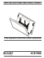
Chief XCB7000 Installation guide
- Category
- Flat panel ceiling mounts
- Type
- Installation guide
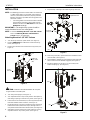
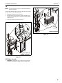
Chief XCB7000 is a heavy-duty ceiling mount designed to support two displays side-by-side with a combined weight of up to 600 lbs. It features a modular design that allows for easy installation and adjustment, and is compatible with a variety of Chief ceiling plates and extension columns. The XCB7000 also offers a wide range of tilt, swivel, and rotation adjustments to ensure optimal viewing angles for your displays.
Chief XCB7000 is a heavy-duty ceiling mount designed to support two displays side-by-side with a combined weight of up to 600 lbs. It features a modular design that allows for easy installation and adjustment, and is compatible with a variety of Chief ceiling plates and extension columns. The XCB7000 also offers a wide range of tilt, swivel, and rotation adjustments to ensure optimal viewing angles for your displays.


-
 1
1
-
 2
2
-
 3
3
-
 4
4
-
 5
5
-
 6
6
-
 7
7
-
 8
8
-
 9
9
-
 10
10
-
 11
11
-
 12
12


Chief XCB7000 Installation guide
- Category
- Flat panel ceiling mounts
- Type
- Installation guide
Chief XCB7000 is a heavy-duty ceiling mount designed to support two displays side-by-side with a combined weight of up to 600 lbs. It features a modular design that allows for easy installation and adjustment, and is compatible with a variety of Chief ceiling plates and extension columns. The XCB7000 also offers a wide range of tilt, swivel, and rotation adjustments to ensure optimal viewing angles for your displays.
Ask a question and I''ll find the answer in the document
Finding information in a document is now easier with AI
Related papers
Other documents
-
Chief Manufacturing PSB-2033 User manual
-
NEC PDWP MB 40 P User manual
-
-
-
NEC X461UNV Miscellaneous Information
-
SunBrite SB-WM46NA Owner's manual
-
-
-
-
Peerless DCT900 Installation guide