Page is loading ...

Protected by U.S. Patents 6,313,990; 6,664,627; 7,167,366; 7,295,436
Other Technology Pending U.S. & World-Wide Patents
Superior Liquid Cooling Systems
®
English v1.2
Exos-2 LX, Exos-2.5
User’s Manual
Exos-2 LX, Exos-2.5
User’s Manual

i
User Manual
This User Manual is updated regularly. Please be sure to check our support page for a newer
version of this guide: www.koolance.com/support
GENERAL PRECAUTION
Please read this manual carefully before beginning the installation of your Koolance system.
This manual assumes the user has basic experience in building and confi guring computer
systems. Information referring to traditional hardware assembly is intentionally brief.
!
WARNING: Indicates a potentially hazardous situation which, if not avoided,
could result in personal injury or be life-threatening.
!
CAUTION: Indicates a potentially hazardous situation which, if not avoided,
may result in damage to equipment.
PROHIBITED: Indicates a prohibited action.
PROHIBITED USE
This product is designed, developed and manufactured as contemplated for general use,
including without limitation: general offi ce use, personal use and household use, but is not
designed, developed and manufactured as contemplated for use accompanying fatal risks or
dangers that, unless extremely high safety is secured, could lead directly to death, personal
injury, severe physical damage or other loss, including without limitation: nuclear power core
control, airplane control, air traffi c control, mass transport operation control, life support,
or weapon launching control. If these products are used in such hazardous environments,
Koolance Incorporated does not warrant them.
TRADEMARKS
The Koolance name and logo, and the Exos name and logo are trademarks or registered trademarks
of Koolance, Inc. Other company and product names used in this publication are for identifi cation
purposes only and may be trademarks or registered trademarks of their respective companies.
COPYRIGHT
All rights reserved. Copyright (C) Koolance Incorporated
ABOUT SIGNS
Throughout this document, critical information is highlighted in gray-colored boxes. The
following symbols are intended to help prevent any situation which may cause personal
injury and/or damage to equipment:

ii
WARNING: The Koolance liquid & coolant pack contain chemicals
which may be harmful or fatal if swallowed. KEEP THIS AND ALL
DANGEROUS CHEMICALS OUT OF THE REACH OF CHILDREN. If
ingestion has occurred, seek medical attention immediately. Give two
glasses of water. Do not induce vomiting. In the case of eye contact,
fl ush eyes immediately with water for 15 minutes. Remove contact
lenses. Call a physician if irritation persists. Some individuals may
have an allergic skin reaction with the solution, although generally mild.
Avoid contact as much as possible, and wash exposed area with soap
and water for at least 15 minutes. If irritation persists, or if contact has
been prolonged, get medical help. For further information, please visit
our website at: www.koolance.com
CAUTION: Koolance Incorporated can not be held responsible for any
damage to your system due to misconfi guration or incorrect installation.
If there is any point of installation that you do not understand, please
contact our Technical Support Staff at: [email protected], or visit
our website at: www.koolance.com/support
CAUTION: Liquid cooling systems are not yet universally supported by
hardware manufacturers. In some situations, adding liquid coolers and
other components to computer hardware might void the manufacturer’s
original warranty. Installation of the device is ultimately done at the user’s
own risk. If you have any specifi c questions on warranty coverage,
please contact your component or computer manufacturer.
!
KOOLANCE CONTACT INFORMATION
Koolance Incorporated (USA)
Address: 2840 W. Valley Hwy. N., Auburn, WA, USA 98001
Telephone: +01-253-893-7551
Fax: +01-253-893-7573
Sales Email: [email protected]
Tech Email: [email protected]
!
!

iii
User Manual
Table of Contents
Introduction 1
Exos System Diagram .................................................................................... 4
LED Display Panel .......................................................................................... 5
Connecting Exos Systems 7
Positioning the Exos ....................................................................................... 8
External Nozzles & Power Cable .................................................................... 9
Connecting the Slot Adapter ......................................................................... 10
Installing the Slot Adapter ............................................................................. 11
Power Connection ......................................................................................... 12
ATX Power Switch......................................................................................... 13
Cooler & Tubing Confi guration ...................................................................... 14
Disconnecting Hoses .................................................................................... 16
Hose Lengths ................................................................................................ 17
Filling & Maintenance 19
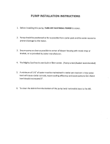
Testing & Filling ............................................................................................. 20
Adding Coolers & Maintenance .................................................................... 22
Troubleshooting ............................................................................................ 23
Limited Warranty ........................................................................................... 26

iv
Exos Series Systems:
- External Power Cable
- Slot Adapter
- Rubber foot pads
- ATX power jumper wire
- user manual
- shutoff nozzles (select models)
Included Hardware
fl at-head screw driver
phillips-head screw driver
pliers
scissors
Required Tools
During installation, you may need the following tools:
long-nose pliers

1
User Manual
Chapter1
Introduction

2
Congratulations on your purchase of a Koolance system!
As the most sophisticated product of its kind, Koolance offers many unique features found
nowhere else in the realm of computer cooling. In addition, you can expect to enjoy all of
the advantages that water-cooling technology brings with it.
Advantages of Water Cooling
Water transfers 30 times faster, and holds over 4 times more heat than air. With
this thermal conductivity and specifi c heat capacity, it’s easy to see why liquid cooling is
getting a lot of attention from hardware manufacturers.
Heat-producing devices in a typical computer are cooled by air. Generally, this involves
mounting a heat sink and fan to each component. For example, heat generated from your
CPU (or other heat source) is transferred into a metal heat sink, where a fan blows air
across its wide surface area.
While altering a heat sink’s size and makeup can improve the effectiveness, it is still
limited because air absorbs and transfers heat very slowly. To help compensate for this,
the fan is often run at a higher speed. Many people have therefore come to equate high
performance with high noise. As systems continued to be upgraded, the required heat
sinks simply got larger and louder.
Liquid cooling greatly reduces the noise issue. A larger amount of heat is withdrawn
from the components more quickly, and less airfl ow is required to cool them.
The heat exchanger is also located remotely from heat-producing devices, so airfl ow can
be controlled. This considerably reduces dust accumulation on sensitive hardware and
can result in a cleaner overall system.
Advantages of Koolance Systems
Koolance is the fi rst company to offer fully-integrated, consumer-level PC liquid cooling
systems to the world-wide market. Our products are designed and built to look and
operate professionally. You will not need power tools or a tape measure to install your
Koolance system, and it should even be less diffi cult than assembling your own computer.
Koolance offers liquid coolers for every major hardware device. Providing enormous
fl exibility, you can customize your system to fi t your specifi c needs— cool dual processors
in a server, multiple hard drives in a RAID confi guration, or add video cooling to a gaming
rig.
Introduction

3
User Manual
The heart of a liquid cooling system is the pump. This device pushes liquid
through each cooler and into the heat exchanger. Koolance systems use dual
pumps to increase reliability and liquid pressure. If one pump should fail, the
second can help prevent potential damage caused by heat increase.
Every Koolance system includes built-in hardware safety features. Our
proprietary power control board constantly monitors liquid temperature, sounding
an alarm if it should get too high, and even turning off your computer if you are
not there to do so.
But Koolance’s innovations extend beyond just cooling features. Our safe,
patent-pending CPU Retention Clip places even pressure across the CPU,
protecting the chip and simplifying installation. There’s even a ratcheting tension
screw for precise contact pressure.
Finally, Koolance systems allow coolers to be easily exchanged and upgraded
to address future hardware compatibility.

4
Introduction
Exos System Diagram
Reservoir & Pump
Radiator Cooling Fans
Reservoir Refi ll Plug
Coolant Inlet
Power Connection
LED Display Panel
Reservoir & Pumps - The coolant tank is grouped with the main pump(s) and is
primarily responsible for bleeding air from the liquid while the system is operating.
It is also translucent for easy liquid-level monitoring.
Power Circuit Board - Beneath the reservoir, the Power Circuit is responsible for
a number of tasks, including: powering the pumps, LED display, heat exchanger
fans, and operating the audio alarm and shutdown modes.
Radiator - The primary heat exchanger is located beneath the fan cooling module.
This is the main cooling element, and provides high thermal dissipation in a
relatively small area. Inside, an aluminum mesh (Louver fi n) is webbed between
horizontal liquid paths.
Coolant Outlet
CAUTION: (Pump speed control models) Due to electrical tolerances,
the lowest pump speed settings may stop the pump from running. Be
sure the pump continues to run when operated at lower speeds.
!

5
User Manual
LED Display Panel
Modes
The Exos-2 LX and Exos-2.5 offers seven display options. All are reached by
continually pressing the SET button:
1. Temperature sensor #1 is displayed
2. Temperature sensor #2 is displayed
3. Temperature sensor #3 is displayed
4. All temperature sensors are cycled automatically
5. Fan setting is displayed (“F” is shown as the mode)
6. Pump setting is displayed (“P” is shown as the mode)
7. All temperatures, fan, and pump settings are cycled automatically
Temperature Sensors
Exos-2 LX and Exos-2.5 systems can monitor up to 3 temperature sensors
(included). The fi rst LED digit indicates which sensor channel is currently displayed
in the temperature reading. To cycle through sensors, press SET.
Fan Speed
This option adjusts the radiator fan speed. Higher speeds can improve performance,
but will produce more noise. There is 1 automatic and 10 manual fan settings (1-
10). From the fan (“F”) or any cycle mode, press the ▼ or ▲ buttons to adjust fan
settings, or hold down an arrow to skip to the lowest or highest mode directly.
Automatic mode will adjust the fans for you based on temperature values from
sensor #1. This mode is reached by lowering the fan setting to “0” (Aut / A will
be displayed).
Pump Speed
There are 10 manual pump settings (1-10). From the pump (“P”) mode, press
CAUTION: Exos-2 LX and Exos-2.5 systems allow full user control of
hardware safety settings, such as audio alarm, shutdown, and pump
speed. Please be sure to confi gure your LED Display Panel properly,
or damage to your computer, data, and/or equipment could result.
!
Current Mode
Value
Mode Select
Display in ºC or ºF
Decrease Setting
Increase Setting

6
Introduction
Alarm & Shutdown Settings
By default, the Koolance audio alarm will sound if any sensor reaches 55ºC (131ºF).
When the system alarm sounds, the appropriate LED temperature will fl ash in the
display and the radiator fans and pump will increase to 100% power.
To change this setting for an individual sensor, choose the desired channel with
SET, and press and hold ▼ + ▲ together for 3 seconds. The alarm temperature
will begin fl ashing. You may change this value from 0ºC (32ºF) up to 99ºC (210ºF).
The normal temperature reading will resume if you do not press any buttons for
4 seconds.
To reset all temperature alarms to their default (55ºC / 131ºF) setting, press and
hold the ºC/F button until “dEF” fl ashes in the display. NOTE: This will also reset
the fan speed mode to “auto”, and pump power to 100%.
If any temperature sensor reaches 3ºC (5ºF) above the alarm temperature, the
system will shutdown power to the computer via the Koolance “ATX pass-through”
wire. With default alarm settings, this means the system will shutdown if any
sensor reaches 58ºC (136ºF).
CAUTION: Generally, sensors report liquid temperature at the water
block, which is typically 5-10°C (9-18°F) lower than the actual heat
source. This difference must be considered if adjusting alarm/shutdown
temperatures. Activating alarm/shutdown modes at too high of tem-
perature can cause hardware damage. Please see the Koolance CPU
water block user manual for information on attaching this sensor.
!
Manual Mode Auto Mode Temperature Range Fan Power % Pump Power %
1 0 - 35ºC (32 - 95ºF) 20 48
2 36 - 37ºC (97 - 99ºF) 24 52
3 38 - 39ºC (100 - 102ºF) 28 56
4 40 - 41ºC (104 - 106ºF) 36 60
5 42 - 43ºC (108 - 109ºF) 44 64
6 44 - 45ºC (111 - 113ºF) 52 68
7 46 - 47ºC (115 - 117ºF) 60 76
8 48 - 49ºC (118 - 120ºF) 72 84
9 50 - 51ºC (122 - 124ºF) 84 92
10 52 - 99ºC (126 - 210ºF) 100 100
the ▼ or ▲ buttons to adjust pump settings, or hold down an arrow to skip to
the lowest or highest mode directly. There is no automatic mode available for the
pump setting.

7
User Manual
Chapter2
Connecting Exos
Systems

8
Positioning the Exos
The Exos is designed to operate in various locations,
but it must run upright. Air fi ltration is not possible in all
orientations.
If the Exos can not be placed adjacent to the computer, it can
be moved farther away. Depending on heat load, 3-6 feet (1-
2 meters) should be an acceptable distance for most Exos
confi gurations.
Extra tubing can be purchased from
Koolance.com or your local reseller.
Connecting Exos Systems
Rubber foot pads are included to place the Exos on or near your computer chassis.
If you are frequently transporting your computer system, an optional “Exos
Attachment Belt” straps the unit to your computer chassis via the metal foot loops
underneath the unit.
Rubber Foot Pad
Attachment Belt

9
User Manual
External Nozzles & Power Cable
Cut the included 10mm (3/8”) tubing into two segments. You will
need to connect each to the Exos’ rear nozzles.
Each tubing connection uses a threaded
compression fi tting (“hose screw”) to keep it
secure. To connect these components, fi rst
thread a hose screw onto the tube end.
Once the hoses are connected, plug the
external power cable into the Exos.
Squeeze the tube while pushing it fi rmly
over the nozzle. Tubing should completely
cover the nozzle.
Tighten the connection by sliding the
compression fi tting down over the nozzle
and screwing securely.

10
Connecting Exos Systems
Connecting the Slot Adapter
The Slot Adapter allows the Exos to connect with any ATX computer through an
available card slot. It is responsible for both input and output tubes, along with
the external power cable connection. This prevents the computer chassis from
requiring any modifi cations for the cooling unit.
There are 5 main internal connections to the Slot Interface card which will be
made. The Exos may appear to operate without some of these connections, but
hardware safety features or temperature monitoring might be deactivated.
Start by connecting Temperature Sensors #1, #2, and #3. Then connect the ATX
Pass-Through wire.
ATX Power
Switch
Pass-Through
Temperature
Sensor #1
Temperature
Sensor #2
Temperature
Sensor #3
Optional Fan
Headers
Main Power
Connection

11
User Manual
Install the Slot Adapter into any available rear
card slot in your computer.
Screw the Slot Adapter in place as you would
a normal device.
From the rear of the case, carefully feed
both ends of the liquid tubing through the
Slot Adapter and into the chassis.
Plug the other end of the Exos’ external
power cable into the Slot Adapter.
Installing the Slot Adapter

12
Connecting Exos Systems
Power Connection
The Exos-2 LX and Exos-2.5 requires approximately 20-30W from any standard
ATX power supply. Since it is adapted internally, it does not need a dedicated
external AC power cable.
Connect the Slot Adapter’s main power plug (12 Volt 4-pin Molex) to the computer’s
power supply. Without this important connection, the Exos will NOT operate.
CAUTION: The Power Connection is vital to system operation. A 12V
4-pin plug from the power supply must remain connected to the cooling
system at all times while the computer is in use.
!

13
User Manual
ATX Power Switch
The ATX “pass through” lead is responsible for shutting off your computer if sensor
channel #1 reaches 3ºC (5ºF) above the preset alarm temperature (See LED Display
for alarm confi guration).
Connect the male ATX power lead from
the Slot Adapter to the chassis main power
button.
Connect the female ATX power lead from
the Slot Adapter to the motherboard’s
power switch connection (often marked
“PWRSW”, “PWSW”, or “PWBT”).
This is the connection that would normally
receive the chassis power switch lead
directly.
CAUTION: The auto shutdown safety features of your Exos will not
function properly without connecting the ATX power switch lead.
!
To Motherboard
To ATX Power Button

14
Series Systems
For systems with only CPU coolers, a simple series loop will provide the best
performance.
Connecting Exos Systems
10
10
10
10
10
CPU
Block
CPU
Block
CPU
Block
Depending on the cooling blocks (“coolers”) in your Koolance system and nozzle
sizes (1/4”, 3/8”, etc.), they may be connected in series, parallel, or a mixture of both
for best performance. Recommended confi gurations are illustrated below.
If you are comfortable experimenting with different tubing setups, there may be
more optimal confi gurations for your particular system.
NOTE: For simplicity, tubing ID (internal diameter) will be listed in metric units.
Please use these approximate conversions for Imperical sizes:
Cooler & Tubing Confi guration
Metric Emperical
6 mm 1/4 in.
10 mm 3/8 in.
13 mm 1/2 in.
Hose Adapter
Hose Splitter

15
User Manual
The maximum number of coolers allowed in a system will depend upon your specifi c
thermal requirements and hose confi guration. It is not uncommon to see fi ve or
more coolers in a Koolance system, but the limit is usually at what temperature you
are comfortable with. Remember, liquid at higher temperatures is still considerably
more effective at carrying heat than air at the same temperature.
Parallel Systems
Koolance coolers which are 6mm (1/4”) can still be effectively used in Exos series
systems. Using a parallel tubing confi guration with hose splitters will help maintain
coolant fl ow rate through these systems.
10
10
10
6
6
6
CPU
Block
GPU
Block
10
6
10
6
6
10
6
6
6
6
10
CPU 1
Block
CPU 2
Block
NB
Block
HD 1
Block
SB
Block
HD 2
Block
/