Emerson Process Management HF300 User manual
- Type
- User manual

www.Fisher.com
D102796X012
FIELDVUE
R
HF300 Series HART
R
Filters
Introduction
Scope of Manual
This instruction manual includes installation and
maintenance information for the FIELDVUE
HF300
Series HART
Filters. Refer to separate manuals for
additional information on other FIELDVUE products
used with the HART filters, such as DVC6000 Series
digital valve controllers, and Type 2530H1 HART
interchange multiplexers.
Control system refers to a distributed control system
(DCS), programmable logic controller (PLC), or a
stand-alone controller that provides a control signal
to the FIELDVUE instrument.
Do not install, operate, or maintain HF300 Series
HART filters without first being fully trained and
qualified in valve, actuator and accessory
installation, operation and maintenance and
carefully reading and understanding the contents of
the manual. If you have any questions about these
instructions, contact your Emerson Process
Management sales office before proceeding.
Description
HF300 Series HART filters, shown in figure 1, are
used with HART-based FIELDVUE instrumentation,
such as DVC6000 Series digital valve controllers.
These filters are used when this instrumentation is
connected to a 4 to 20 mA DC control system output
that was not designed for the HART (Highway
Addressable Remote Transducer) communication
protocol.
The HF300 Series HART filters consist of the Type
HF340 HART filter that provides filtering and
isolation between the control system and FIELDVUE
instrument and the Type HF341 communication tap.
The Type HF341 does not provide any filtering. It is
simply a straight through device that provides a
convenient connection for HART communication.
FIELD INSTRUMENT CONNECTIONS (FLD)
HART COMMUNICATION
CONNECTIONS (COMM)
CONTROL SYSTEM
CONNECTIONS (SYS)
W8283 / IL
Figure 1. FIELDVUE
HF300 Series HART
Filters
The Type HF340 HART filter is a passive device that
is inserted in-line with both wires of a HART 4 to 20
mA DC output loop. The purpose of the filter is to
effectively isolate the control system analog output
from modulated HART communication signals. The
filter receives a 4 to 20 mA DC current signal from
the control system, which it shunts with a capacitor
and then passes through an inductor. The low AC
impedance of the capacitor prevents sudden
changes in the control system current output from
interfering with the HART communication. The high
AC impedance of the inductor permits HART
communication on the instrument side of the filter. It
also prevents the voltage modulation in the HART
loop from being seen by, or having an affect on, the
control system output. The filter introduces a
maximum input-to-output voltage drop of 2 volts DC
at 20 mA as long as the output load voltage is less
than 14 volts DC.
Instruction Manual
Form 5715
June 2007
HF300 Series

HF300 Series
Instruction Manual
Form 5715
June 2007
2
Table 1. Specifications
Product Types
Type HF340: Standard 35 mm DIN rail mounting
with filtering components.
Type HF341: Standard 35 mm DIN rail mounting
without filtering components (straight through with
capacitor blocking on COMM terminals).
Connections
Three 2-pin Cage-clamp style connectors
accept up to 12 AWG wire
Power Requirements (Type HF340 only)
Input Current: 4−20 mA DC (nominal)
Input Voltage: At 20 milliamps DC, 2 volts above
input voltage required by the field instrument (2
volt drop across filter at 20 milliamps DC)
Filter Output
Filter output is clamped at 15 volts DC. Filter load
voltage requirement must not exceed 14 volts DC
Ambient Operating Temperature
−40 to 85C (−40 to 185F)
Ambient Relative Humidity
5 to 95%
Electromagnetic Interference (EMI)
These units have the CE mark in accordance with
the European Electromagnetic Compatibility
(EMC) Directive. They meet the emissions
requirements of IEC 61326-1 (Edition 1.1) for
Class A equipment for use in industrial locations
and Class B equipment for use in domestic
locations. They also meet the immunity
requirements listed in table 2 below. This table is
in accordance with Annex A of IEC 61326-1 for
equipment intended for use in industrial locations.
Dimensions
75 mm (3 inches) long by 12.5 mm (0.5 inches)
wide by 60 mm (2.4 inches) deep
Approximate Weight
0.1 kg (4 oz)
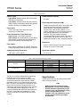
Table 2. EMC Immunity Performance Criteria
Port Phenomenon Basic Standard Performance Criteria
Enclosure
Electrostatic discharge (ESD) IEC 61000-4-2 A
EM field IEC 61000-4-3 A
Rated power frequency magnetic field IEC 61000-4-8 N/A
(1)
I/O signal/control
Burst IEC 61000-4-4 A
Surge IEC 61000-4-5 A
Conducted RF IEC 61000-4-6 A
1. Not applicable; only applicable to magnetically sensitive equipment.
The filter is normally installed near the field wiring
terminals of the control system I/O. HART
communication is only possible between the filter
and the field instrument and at the filter COMM
terminals, but not on the control system side of the
filter. The filter is not designed or intended for use in
the process environment. Neither the filter nor its
outputs are approved for hazardous areas. However,
a recommended intrinsic safety barrier can be
connected between the FIELDVUE instrument and
the filter in intrinsically safe installations. In most
cases, if an IS barrier is used, the filter will not be
needed.
Specifications
Typical specifications for the HF300 Series HART
filters are shown in table 1.
Note
Neither Emerson, Emerson Process
Management, nor any of their affiliated
entities assumes responsibility for the
selection, use, and maintenance of any
product. Responsibility for the
selection, use, and maintenance of any
product remains with the purchaser
and end-user.

HF300 Series
Instruction Manual
Form 5715
June 2007
3
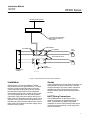
CONTROL
SYSTEM OUTPUT
TERMINALS
TYPE 2530H1 HART INTERCHANGE
MULTIPLEXER OR OTHER HART
MULTIPLEXER
FIELD
DEVICES
+
+
+
−
−
−
FLD TERMINALS
COMM TERMINALS
HF300 SERIES HART FILTER
+
+
−−
SYS TERMINALS
HART MULTIPLEXER NETWORK
375 FIELD
COMMUNICATOR
+
−
Figure 2. Typical HF300 Series HART Filter Installation
Installation
Refer to figure 2 for typical installations. HF300
Series filters mount on a type 35 DIN rail. To install
the filter, provide a temporary means of process
control, then take the loop out of service. Remove
the DIN interconnect blocks from the rail without
disconnecting existing wiring. Install the filter on the
rail. Disconnect the wires from the control system
output side of the interconnect blocks and connect
them to the SYS terminals on the filter, taking care to
maintain correct polarity. Disconnect the wires from
the field side of the interconnect blocks and connect
them to the FLD terminals on the filter, taking care to
maintain correct polarity.
Shields
If using shielded wiring on both sides of the filter, the
shield should connect across the filter. If the filter
connects directly to the control system output and
shielded loop wiring is being used, connect the
shield to system ground on the instrument side of
the filter.
HART Wiring Connections
The COMM terminals on the filter provide a
convenient means to tap into the loop wiring for
HART communication. A HART Interchange
multiplexer or the 375 Field Communicator can be
connected to these terminals, or they may be left
with no connections.

HF300 Series
Instruction Manual
Form 5715
June 2007
4
Corrective Maintenance
The most likely malfunction of a loop containing an
HF300 Series HART filter is reverse polarity
installation of one of the wire pairs. The Type HF340
filter will work with either polarity, but misconnection
could result in the wrong polarity reaching the field
instrument. If the loop is not operating properly,
check the polarity of the voltage at the inputs and
outputs of the filter and at the inputs of the
instrument.
If the instrument appears to operate properly in the
loop, but communication with a non-isolated
multiplexer or PC modem is not possible, it may help
to reverse the wires to the COMM terminals. The
Type HF340 filter inserts a high impedance in the +
side of the loop only. A reversal of the connections
to the SYS and FLD terminals of the filter will result
in the control loop operating properly, but inoperative
HART communication.
Inadequate control system compliance voltage will
not support filter operation. This is an installation
problem that may appear initially to be a filter
malfunction. For the filter to operate properly, the
control system must have a compliance voltage that
is at least 2 volts higher than the voltage required to
drive the loop to maximum current. Refer to the
appropriate instrument instruction manual for
information on determining the control system
compliance voltage.
Excessive load voltage will interfere with filter
operation. A transient clamping device limits the
output voltage to a nominal 15 volts. If the voltage at
the output (due to the total impedances connected)
is greater than 14 volts DC at maximum loop current,
some of the current may be shunted by the clamping
device.
The Type HF340 filter is protected against accidental
over-current from sources up to 30 volts DC. If an
over-current condition occurs, the filter may be
inoperative for several seconds thereafter.
Emerson Process Management
Marshalltown, Iowa 50158 USA
Cernay 68700 France
Sao Paulo 05424 Brazil
Singapore 128461
www.Fisher.com
The contents of this publication are presented for informational purposes only, and while every effort has been made to ensure their accuracy, they are
not to be construed as warranties or guarantees, express or implied, regarding the products or services described herein or their use or applicability.
We reserve the right to modify or improve the designs or specifications of such products at any time without notice.
Neither Emerson, Emerson Process Management, nor any of their affiliated entities assumes responsibility for the selection, use and
maintenance of any product. Responsibility for the selection, use and maintenance of any product remains with the purchaser and end-user.
Fisher Controls International LLC 2001, 2007; All Rights Reserved Printed in USA
Fisher and FIELDVUE are marks owned by Fisher Controls International LLC, a member of the Emerson Process Management business division of
Emerson Electric Co. Emerson Process Management, Emerson, and the Emerson logo are trademarks and service marks of Emerson Electric Co.
HART is a mark owned by the HART Communication Foundation. All other marks are the property of their respective owners.
-
 1
1
-
 2
2
-
 3
3
-
 4
4


Emerson Process Management HF300 User manual
- Type
- User manual
Ask a question and I''ll find the answer in the document
Finding information in a document is now easier with AI
Other documents
-
Emerson FIELDVUEDVC2000 User manual
-
-
-
Pepperl+Fuchs HiSHPTB/32/TR-AI-01-Y1 Owner's manual
-
-
-
-
Fisher FIELDVUE DVC7K Digital Valve Controller User manual
-
AMS Online Licensing Procedure Owner's manual
-