Page is loading ...

-
mira 722 series thennostatic mixing valves
INSTALLATION ADVICE
Installer. This leaflet is the property of the customer and must be left with the user.
722 (exposed) valves are being supplied as bottom outlet, with
the drain plug in the top.
722B (concealed valves are being supplied as top outlet with
drain plug in bottom.
Always connect HOT water to REDinlet, COLDwater to inlet
marked BLUE.
The drain plug can be re-positioned to obtain the correct
outlet position. REFERTO CHART BEl1JW.
bir-sbif-s
r~\
t'CJ.I
Top Outlet
~1%1\L~)
\,." J
biv..s
er-s
ef-s
,
I
J
Shower Fittings. Refer separate leaflet P1069/3
ev-s
Bottom Outlet
\ II '
, ;
~/~
Flow control is incorporated in the mixing valve, eliminating
the need for check valves on the inlets. No form of flow control
should be fitted on the outlet.
Conveniently situated isolating valves for servicing purposes
should be fitted.
Installations must comply with requirements of local water
authority by-laws.
Mira 722L, 722LB (low capacity) also Mira 722E, 722EB (lever
action) models are installed similarly as described for Mira 722,
Mira 722B models.
Important Points
In the UK, hot and cold supplies MUST originate from a cold
water cistern and must NOT be connected directly to the cold
water main.
Certain types of instantaneous water heaters can be used, but we
must first be consulted. There is an approved layout which must
be followed. All information necessary iEavailable on request.
Pressures
Minimum static to discharge point e.g. spray head 9kPa (3ft
head). *The absolute minimum head is 2ft. In such cases short
pipe runs must be used and good plumbing practicelfollowed.
Under these conditions the flow rate will be approxiinately 3.5
litres per minute (and the performance of thermostatic controls
could be slightly impaired). Maximum static 825 kPa
(120Ibf/in2).
Note: Minimum pressures with minimum pipe runs requires
vertical distance from bottom of cold cistern to discharge point to
be 0.92m (3ft). Due allowance must be made for longer pipe runs.
Where hot and cold pressures are unequal the ratio between
them must not exceed 5:1 e.g. higher pressure must not be more
than five times lower pressure.
Layout and sizing of pipework must be such that when other
services are used, pressures at inlets do not fall below
recommended minimum.
Supply lines should be flushed until water is clear, before
mixing valve is connected.
Where insufficient pressure exists, or a more forceful spray
required, certain types ofpumps can be used, but we must first be
consulted. There is an approved layout which must be followed.
All information necessary is available on request.
Connections Inlets/outlet: 1/2inBSP
Connect HOT water to inlet marked REDand COLDwater to
inlet marked BLUE.Connections, when facing mixing valve, are
hot left, cold right.
6~34:4~~3017
09001
dill .
5~2 28
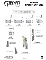
Figure2
l
130mm
J
•...'
Figure 5
75mm (2'~/".jn) inlet faces
IFigure4
Min 73mm (2~/~in)
I I
Figure3
6. Shower Fittings
Where being installed; refer separate leaflet P1069/3 'Shower
Fittings'.
7. Re-fit shroud, hold in place by re-fitting shroud transit screw
(Figure 5).
8. Plaster and tile up to sides to shroud, so that FINAL wall face
rests on the RIDGEwidth of the building in shroud. When set,
remove shroud transit screw and remove shroud or cut
around it at wall surface.
Installation. Mira 722, 722L, 722E
1. Backplate (055 08) is attached to base by bayonet type fitting.
Turn to remove (Figure 1).Fix backplate to wall using wall
screws (611 37) provided, with guide lines vertical or
horizontal (Figure 1).Re-fit base to backplate.
2. Refer Connections within Important Points before connecting
supplies. Assemble inlet union elbow fittings as shown in
Figure 2. Where pipe concealing plates are used, guide these
over elbow threads. Hold back firmly on mixing valve when
tightening inlet connections.
3. Check position of outlet, if necessary re-position drain plug.
4. Shower Fittings
Where being installed, refer separate leaflet P1069/3 'Shower
Fittings'.
Installation. Mira 7228, 722LB, 722EB
1. Supplied with additional fittings so that it can be built into a
wall, including a building in shroud for protection and
guidance during installation and wall fmishing.
2. The DEPTH of concealment MUST be such that the FINAL
wall face (plaster, tiles, etc.) rests on the RIDGEwidth of the
building in shroud (Figure 5).
3. When wall has been chased out to correct depth (Figure 3),
remove shroud. Keep shroud for later use.
4. Back plate (052 09) isattached to base by bayonet type fitting.
Turn to remove (Figure 1).Fix back plate inrecess using wall
screws (611 37) provided, with guide lines vertical or
horizontal (Figure 4). Re-fitbase to back plate.
5. Supplies
Check position of outlet; ifnecessary re-position drain plug.
Connect HOT water to inlet marked RED.
Connect COLD water to inlet marked BLUE.
Support inlet pipes rigidly.
Hold back firmly on mixing valve when tightening inlet
connections.

9. Fit nameplate and flow control knob bolt (supplied loose in
fittings packet). Angle mounting bracket assembly (807 06)
over temperature regulating lever and attach to back plate
with bracket screws (60990), so that its plastic ends are 'left
and right' not 'teJpand bottom' (Figure 6),Donot over-tighten
scre\ys:
10. Angle-concealing plate (076 01) over temperature regulating
lever and locate it in posHion on mounting bracket (Figure 6).
Then press so it snaps into position.
Operation and Maintenance Advice
(including G72 Series)
Operation
Turn flow control knob anti-clockwise until desired forceof water
is obtained.
Turn temperature regulating assembly lever until desired
temperature of water is obtained.
MaxiqmIn temperature of water at discharge point can be
regulated so that water at too high a temperature is not obtained at
discharge point e.g. spray head.
To check maximum temperature. Ensure an adequate supply of
HOT water is available at a temperature in ex(;esSof that required
from the mixing valve, turn on flow control and move lever to
position 5.
Check temperature with thermometer at discharge point. For
shower use, recommended temperature setting is approximately
43°C (110°F).
Re-setting Maximum Temperature
Remove flow control knob bolt (610 80), nameplate and flow
control knob (039 09). Unscrew 2attachment screws (602 26)and
remm'etemperature regulating assembly (800 01) from cover
(Figure 9).
Grip larger protruding spline by hand, rotating it (clockwise) to
increase temperature (anti-clockwi'se to decrease temperature)
until desired maximum temperature is obtained at discharge
point.
Set lever on scale to position 5 (Figure 10).Hold in this position
and replace onto cover, aligning attachment screw holes with 2
holes in cover. Replace attachment screws, do not over-tighten.
Replace flow control knob, nameplate and bolt.
~t~o~FI,~«A
Maintenance
Ifa new mixing valve fails to operate satisfactorily it isusually the
result of incorrect installation and the installer should be
consulted. The Diagnosis Chart which follows will assist you in
identifying the reason why your new mixing valve is not
~perating satisfactorily.
Refer Important Points within Installation Advice for
conditions within which mixing valve should be installed.
If the mixing valve has operated satisfactorily for a time and no
longer gives satisfaction, it is possible that service is necessary.
Please note that the internal parts should be kept clean and such
work is not included within the guarantee. The Servicing
-Procedures advice which follows will assist you in the method of
maintenance. Our experience has shown that due to the
simplicity of design, the average user is capable of cleaning the
internal parts, replacing seals, or if necessary, fitting a
replacement cartridge assembly.
You may, if you wish, choose to engage the services ofa suitably
qualified person locally.
Gold Plated Products
Gold is softer than chrome and its abrasive resistance much less.
When cleaning, or using tools during servicing, extra care should
be taken.
Cleaning
Gold plated fittings should be cleaned with a soft cloth and if
necessary a mild washing up detergent or soap solution and then
rinsed and rubbed dry.
Warning
Many modern household cleaners contain mild abrasives, as well
as chemicals and should never be used for cleaning gold, or
chrome plated fittings.
Servicing Procedure
Refer Figure 13 below for identification of parts and sequence of
assembly.
Concealed models (722B
& G72B). Remove concealing fittings.
722B:- Prise offconcealing plate (from centre, not ends). Unscrew
bracket screws and lift offassembly mounting bracket (Figure 11).
G72B:- Unscrew adjusting screws and lift offconcealing plate
(Figure 12).
Dismantling - All models
1. Turn offwater supplies to mixing valve. Open flow control to
release built-up pressure, then remove flow control knob bolt,
nameplate and flow control knob.
2. Unscrew 2 attachment screws and pull or prise off
temperature regulating assembly.
3, Unscrew 4 cover screws and pull offcover. Do not lose cover
joint, invariably found stuck in recess ofbase. Push out
thermostat assembly from cover or remove from position on
port assembly.
4. Lift outside spring of flow control spindle ('E' models only).
5. Slacken offhead assembly with an adjustable spanner.
6. Pull offport sleeve from port assembly. (Ifstuck, wrap a piece of
clotharoundsleevetoassist removal. Donot resort to use of metal
grips.) Pull port assembly from base. Ifnecessary, as an extra
grip, replace control knob and bolt onto flow control spindle.
Figure 7
Clamping bracket
screws and nuts·
Figure 8
•Optional extras
Clamping bracket·
Panel Mounting. Mira 722B, 722LBand 722EB
1. Suitable for fitting into panels up to 16mm (5/8in) thick.
2. The building in shroud is not used when panel mounting, so
remove and discard this part.
3. Cut panel to dimension shown in (Figure 8)
4. Remove back plate (05209) (Figure 1)and fit to clamping
bracket (118 72)with clamping bracket screws (606 78)and
nuts (621 30) (Figure 8),which are available as optional extras.
5. Feed the mixing valve through the panel hole, from the back,
and connect inlet supplies.
6. Supplies '
Connect Hot water to inlet marked RED.
Connect COLD water to inlet marked BLUE.
Hold back firmly on mixing valve when tightening inlet
connections. Note. It is essential that inlet and outlet pipes are
rigidly supported.
7. Check position of outlet, if necessary re-position drain plug.
8. Shower Fittings .
Where being installed, refer separate leaflet
P1069/3 'Shower
Fittings'
9. Fit mounting bracket assembly (807 06) and concealing plate
(076 01) as described within Installation Mira 722B, 722LB
and 722EB, paragraphs 9 and 10.

Port a"ssembly , I~side spring
Th thrust washer I E models only)
Cover ~ ~ // / er~ostat Cover
I il,iifW' Port sleeve
f(JII=I' / ~ COL;J'Iseal ~ (to be free to move)
Cover screw Outside spring
IE models only) I
~ Thermostat assemblv
~ I - Port assembly
, I
Cartridge assembly
~c~~~~r\~~t~nkr.~t free Thermostat actuator lug location slot Base lug for port assembly location
retentfon cage
Figure 13
Re-assembly
13. Re-assemble in reverse order to above, ensuring cut-away
section of flange of port assembly and large cut -away section
in sleeve locate over lug in base.
14. Replace inside spring over flow control spindle before
screwing spindle into head assembly ('E' models only).
15. Ensure small white port assembly thrust washer lies flat on
shoulder of head nut.
16. Replaceoutside sping over flow control spindle ('E' models only).
17. Fit thermostat assembly over flow control spindle, ensuring
lug(s) locate and engage into small slot(s) on flange ofsleeve.
18. Ensure large white thermostat assembly thrust washer lies flat
on shoulder of thermostat spindle.
19. Ensure cover joint is in position, Fit cover, with attachment
screw holes horizontal, over thermostat spindle and fasten to
base. Close flow control spindle.
20. Turn on water supplies to mixing valve and check for leaks,
then open flow control spindle.
21. Select maximum temperature of water required by turning
thermostat spindle anti-clockwise for cold or clockwise for hot.
22. Check temperature regulating assembly has not had splined
bush stripped. If it has, remove retention screws from back
and turn bush
1800 and re-assemble.
23. Adjust the maximum temperature setting and complete
re-assembly, as described in 'Re-Setting Maximum
Temperature'. Re-check maximum temperature of shower.
Shower Head (if of our manufacture)
24. If shower pattern from shower head is not satisfactory,
remove centre screw and plate(s). Clean flutes in plates with
stiff bristled brush then re-assemble.
25. Spare plates and screws are available direct from Service
Department.
G72B
Concealing plate
Adjusting screws
Figure 12
7. Totally remove head assembly and screw out flow control
spindle.
Cleaning/Replacement of Parts
8. Parts may be cleaned using a proprietory inhibited scale
solvent e.g., Kettle descalent.
Note. Care must be taken not to allow solvent to come into
contact with bathroom fittings and swfaces.
9. Check that lugged actuator within retaining ring of
thermostat coil is free to move.
10. Polish mating surfaces of port pillar and sleeve with metal
polish e.g. Brasso.
11. Check all seals and replace ifnecessary. Remove seals by
cutting with razor blade or sharp knife. Donot damage seal
grooves. Lightly smear all seals, also threads of spindle with
petroleum jelly or similar grease. Sets of seals in packaged
form (935 15) are available direct from Service Department.
12. If the cartridge assembly is beyond repair, please contact
Walker Crosweller's Service Department by letter or
telephone for the current price of a replacement cartridge
assembly. Please be sure toquote the nameplate details ofthe
mixing valve. Also refer to (Figures 14, 15
& 16) for assistance
in correct identification ofcartridge assemblies.
Flo\\' cootroll 'f"" 1
knoh holt Flow control knob
Namt~plah:
Spl
ilWei hush
(should nol rnlate
O\'t:r
It:\'t~rquadrant -1t..'Clh MelalleveT with
slripped if
iIdocs) toolhed quadranllhousedl
Diagnosis Otart
Symptom
Hot water supplied by the mixing valve
when the temperature control is in the
cold position or vice versa.
Only cold and warm water obtainable
with a high pressure spray in the cold
position and a lower pressure spray in
the warm position.
Mixing valve operates satisfactorily
until other domestic services are
brought into use.
Leaks from shower fittings of pipework.
Possible Reason
Mixing valve installed with hot water
connected to the cold water inlet. Hot
water should normally be connected to
left inlet when facing unit.
Cold water inlet fed directly from cold
water mains supply. Both hot and cold
supplies should originate from the cold
water cistern.
As the thermostat compensates for
normal variations in pressure, it is likely
that the plumbing design is such that
excessive reductions in pressure are
occuring.
Unions or joints require tightening.
Action
Request installer to investigate and
rectify. (Also refer 'Reversed Inlets')
Request installer to investigate and
rectify.
Request installer to investigate and
rectify.
Request installer to rectify.
Persistent leak from shower head (not
to be confused with dripping which
can occur for a while after shower has
been in use).
Seals have become damaged by foreign
matter in water supplies.
A setof seals with instructions may
be purchased. Ifleak continues
fit a replacement cartridge
assembly.

Symptom
Flow of water from shower head is
insufficient for satisfactory shower.
Possible Reason
Minimum pressure requirements not
observed. Vertical distance from
bottom of cold water cistern to shower
head should be 3ft minimum.
Spray plates are,blocked by foreign
matter in water supply.
Partial blockage or airlock in
pipework.
Shower head in use (not of our
manufactOre) unsuitable for low
pressures.
Action
Request installer to investigate and
rectify .
Remove and clean spray plates by
brushing out flutes.
Request installer to investigate and
rectify.
Fit shower head of our manufacture.
Temperature satisfactory at first but
fails before the shower is completed.
Maximum temperature obtainable is
either too high or too low.
No temperature control after
period of satisfactory use.
Hot water storage temperature is not
being maintained. The mixing valve
must be supplied with hot water which
is always well in excess of the mixed
temperature required.
Maximum temperature requires
re-setting.
Build up of deposits on internal parts,
Ensure hot water storage temperature
is adequately maintained, preferably
at least 20"Cabove the showering
temperature.
Re-set the maximum temperature ~y
following the instructions on page 3.
Clean internal parts - refer
'Servicing Procedure'.
outerspring
*Refer Reversed Inlets below
Nameplates
043 01 Nameplate (G72,GnB)
043 02 Nameplate (GnL, GnLB)
043 06 Nameplate (G72E,
GnEB)
StandardModels squareportIngs Lowcapacity[L) triangularportings
(90221) 722,722B.G72&G72B models[90223) 722L,722LB.G72L&G72LB
Figure14 ~ IFigure15~~portsleeve ~portsleeve
4mm[5/32")holes ridge' 2mm[3/32")holes ridge'
G72 Series Spares Only L '(E) .
I rt'
XC ever actIon tnangu ar po mgs
G72 (e models) models(90225) 722E,722EB.G72E&G72EB
058 01 ackplate retaining spigot .(}
05601 Backplate Figure 16.Jr/1
60814 Backplateretaining screw
G72B(concealed models)
075 01 Concealing plate
61005 Adjusting screws (2)
053 09 Backplate
609 60 Backplate retaining bolt
556 43 Locating pin
All G72models
001 01 Cover
003 01 Body
61007 Coverscrews (4)
Identification of Carbidge Assemblies
The cartridge assembly is the combined port and thermostat
assemblies, which are supplied for user service as a complete
replacement cartridge assembly,
Cartridge assemblies for Mira 722 Series can be used for G72
Series thermostatic mixing valves. Ifordering other spare parts for
G72 with the exception of as below, order as for Mira 722 Series.
Important. When ordering a replacement cartridge assembly be
sure to quote the nameplate details of the mixing valve. Refer
Figures 14, 15 and 16 which illustrate the differences between
standard, low capacity
(1) and lever action (E)cartridge
assemblies. Identity ofthe removed cartridge assembly can be
checked from Figures 14, 15 and 16.
Note. Thermostat assemblies are common to standard, low
capacity
(1) and lever action (E)models. Figures 14, 15 and 16
therefore illustrate the port assemblies only and identify the
differences.
Parts List
When ordering spare parts quote, type ofmixing valve, code
number and name of component.
001 03 Cover
003 03 Base
03017 Union elbow (2)
039 09 Flow control knob
041 01 Flow control lever (722E)
044 60 Nameplate (722)
04461 Nameplate (722E)
044 62 Nameplate (122M)
044 63 Nameplate (722L)
050 01 Inside spring (722E)
050 02 Outside spring (722E)
052 09 Backplate
055 08 Backplate
076 01 Concealing plate
089 03 Drain plug
090 01 Pipe concealing plate (2)
*11872 Clamping bracket *
552 28 Nipple adaptor (2)
606 26 Screw -attachment (2)
Figure17
~04101
~
*Optional extras
*60678 Screw-clamping bracket(2)
606 90 Screw- bracket(2)
61014 Screw- cover (4)
61080 Flow control knobbolt
611 37 Screw-wall (2)
*621 30 Clamping bracketnut(2)
624 09 Union riut (2)
632 38 Coverjoint
63409 Gasket(4)
634 56 Gasket
636 17 Head thrust washer
636 25 Thermostat assemblythrustwasher
800 01 Temperature regulatingassembly
*805 15 Clampbracket assembly
807 06 Mounting bracketassembly
902 21 Cartridge assembly(722)
902 22 Cartridge assembly(722reversed)
902 23 Cartridge assembly(722L,722M)
902 24 Cartridgeassembly(722L,722Mreversed)
902 25 Cartridge assembly(722E)
902 26 Cartridge assembly(722Ereversed)
93515 Setofseals
Part numbers for complete replacement 'reversed' cartridge
assemblies for Mira 722 or G72 Series are
Reversed Inlets
REVERSED INLETS. (Referitem 1 ofDiagnosis Chart). This can
usually be corrected by crossing the inlet supplies at a convenient
point e.g. in the roof space. Ifthis is not possible, a 'reversed'
cartridge assembly is obtained from Service Department,
identified by the absence of the ridge mid-way on the port sleeve.
Standard
Models
902 22
Low Capacity
Models
902 24
Lever Action
Models
902 26
MiraisaregisteredtrademarkofCaradonMiraLimited.
Republic
of Ireland Tnecompanyreservestherighttoalterproductspecificationswithoutnotice.
Modern Plant Ltd.
A ('"",adoncompany
Otter House, Naas Road, Clondalkin,
Co. Dublin, Eire. tel. 591344 telex. El93657
Caradon Mira
Caradon Mira Limited
Cromwell Road, Cheltenham GL52 5EP
tel. 0242 221221 telex. 43242
P1162/6
PrintedinUK·T
© CaradonMiraLimited,September
1987
/