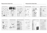
12. Install the outlet pipework and connect to the
showercontrol.Takingintoaccountthenished
wall thickness ensure the pipework extends far
enoughfromthewall(atleast15mm)toallow
fortheshower outlet tobe tted. Check for
water leaks.
13. Fit the building-in shroud over the valve in the
recess.Plasterandtile,ornishasappropriate,
up to edge of the building-in shroud. The nal
wall surface must fall between the 2 lines
on the building-in shroud.
7. Remove the control knobs and locknuts (refer
to Removing/Fitting Knob and Concealing
Plate Assemblies) and fit the building-in
shroud over the valve.
8. Mark the position of the wall mounting bracket
xing holes. Drill a 6.0 mm diameter hole at
each of the marked positions and insert the
wallplugs(supplied).
9. Remove the building-in shroud and install the
hot and cold supply pipes.
10. Flush the hot and cold water supply pipes thoroughly. The supplies must
be clean and free from debris before connecting the shower control. Failure
to do so may result in product malfunction.
11. Mount the shower control in the recess and connect the inlet pipework. Check
the hot and cold supplies have been connected to the correct inlets. If necessary
the valve inlets can be reversed, refer to Reversed Inlet Supplies for further
information.
Note!Ifthewallscrewscannotbexedintothewall,tthebuilding-inshroud
andllthecavitybehindthemountingbracketwithanappropriatematerial(e.g.
expandiblefoam).
14. When the wall surface has been completed, remove the building-in shroud. If
necessary cut the shroud to help removal.
15. Fitthesupportbracket(withtheTshapedholeatthetop),theconcealingplate
seals and the concealing plate to the valve. To ensure an effective seal the
mainsealwillneedtobettedwiththesmoothsidefacingthewall.Cutthetabs
awayfromthemainsealbeforettingtheconcealingplate(refertoRemoving/
Fitting Knob and Concealing Plate Assemblies).
Note! Should the wall surface or tiling be uneven, the seal will need to be aided
or substituted with silicone sealant.


