
Rev. 6-18-13 - QTmc
1
Part Number 12750
©2013 Edelbrock LLC
®
PLEASE read these instructions carefully before attempting to rebuild your carburetor. Make sure to refer to your carburetor
Owner’s Manual for further information if needed. If you have any questions, do not hesitate to contact our Technical Hotline
at :1-800-416-8628, 7am-5pm PST, Monday-Friday.
4160-Style Carburetor Rebuild Kit
Part #12750
INSTALLATION INSTRUCTIONS
Please note that this is a general guideline and may not
cover every step required to rebuild your specific carburetor.
Please refer to your carburetor’s owner’s manual for any
additional information.
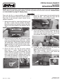
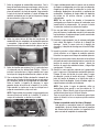
1. Remove the four bolts or screws from the primary and
four bolts or screws from the secondary fuel bowls.
Remove the washers from the bolts or screws and match
them up to the ones provided in the rebuild kit and set
aside.
2. Remove the primary fuel bowl and metering block, being
careful to not damage the fuel transfer tube. Carefully
remove the gaskets found between the primary fuel bowl
and metering block. Match up the gaskets removed to
the ones provided in the rebuild kit and set them aside.
NOTE: If fuel bowl is stuck, gently tap with the handle
end of a screwdriver to break free.
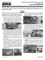
3. Remove the power valve from the primary metering
block using a 1” wrench. Identify the power valve
number stamped on the face of the power valve and
match it to the one provided in the kit. If the provided
power valve does not match, additional power valves
are available from Edelbrock. Remove the jets from the
primary metering block with a flathead screwdriver.
4. Using a 5/8” wrench, remove the inlet needle from the
primary fuel bowl. Then remove the screw and the
adjustment nut from the inlet needle assembly.
5. Using a small flathead screwdriver, remove both idle mix
screws from the primary metering block. Pull out the
small cork O-rings and match the cork O-rings to the
ones provided in the rebuild kit and set aside.
6. Remove the pump cover attached to the primary fuel
bowl and remove the pump diaphragm.
NOTE: Some carburetors will have a check ball or a
rubber check. If a rubber check is used, remove and
replace with the one provided in the kit.
DISASSEMBLY

Rev. 6-18-13 - QTmc
2
Part Number 12750
©2013 Edelbrock LLC
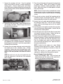
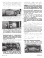
7. Remove the secondary fuel bowl. Using the provided
clutch head screw bit, remove six screws securing the
metering plate. Remove metering plate and backup
plate. Match up the metering plate gasket and secondary
metering block gasket to the ones provided in the rebuild
kit and set aside.
8. Remove the fuel transfer tube O-rings from both primary
and secondary fuel bowls. Match O-rings to the ones in
the rebuild kit and set aside.
9. Remove the screws securing (6 or 8) the base plate to
the carburetor with a Phillips screwdriver. Remove the
baseplate gasket and match it up to the one provided in
the rebuild kit and set aside.
10. Unscrew the accel pump discharge nozzle found within
the throttle bore of the carburetor using a Phillips
screwdriver. Remove the screw, discharge nozzle, small
needle inside the nozzle hole and gaskets. Match up the
gaskets to the ones provided in the rebuild kit and set
aside.
NOTE: Be careful not to lose the small needle that rests
inside the nozzle hole. It will slide out if the carburetor
body is flipped.
11. Clean all parts thoroughly with approved cleaning solvent
or lacquer thinner. Make sure to remove all gasket
residue from carburetor, metering block/plate, and fuel
bowls. Make sure to clean all carbon deposits in throttle
bores and passages.
NOTE: Do not use wire brushes or pointed tools to clean
carburetor parts as they may damage the components.
Do not immerse rubber or similar materials in cleaning
solvent.
12. Once all parts are clean, reinstall the baseplate onto the
carburetor using the new baseplate gasket. Make sure
the provided gasket matches the original gasket.
13. Reinstall the small needle (pointed end down) back into
the discharge nozzle hole. Install the new discharge
nozzle gasket and discharge nozzle with the original
Phillips screw.
14. Insert the power valve gasket and install the new power
valve into the primary metering block. Reinstall the jets
into the primary metering block.
15. Insert the new cork O-rings into the idle mix screw holes
and reinstall the idle mix screws. Tighten the idle mix
screws, then back them out exactly 1.5 turns.
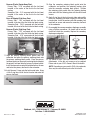
16. Screw the new inlet needle into the needle provision on
the primary fuel bowl. Place the adjustment screw gasket
onto the inlet needle and install the adjustment screw.
Place the locking screw gasket onto the adjustment
screw and install the locking screw. Adjust the float to
the specs provided below.
NOTE: To adjust the inlet needle, use a large flathead
screwdriver and an open-end 5/8” wrench. Loosen the
screw and turn the adjusting nut clockwise to lower the
float level.
Please note that this is a general guideline for float
adjustments, additional fine tuning may be required.
Brass & Nitrophyl Center Hung Float:
Primary and Secondary Side - Invert fuel bowl and
adjust the float until the surface of the center float is
parallel to the fuel bowl casting surface.

Rev. 6-18-13 - QTmc
3
Part Number 12750
©2013 Edelbrock LLC
Edelbrock, LLC • 2700 California St. • Torrance, CA 90503
Tech Line: 1-800-416-8628
®
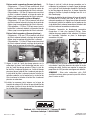
Duracon (Plastic) Center Hung Float:
Primary Side - 5/16” measured with the fuel bowl
inverted, at the center of the float to the fuel bowl
casting.
Secondary Side - 3/8” measured with the fuel bowl
inverted, at the center of the float to the fuel bowl
casting.
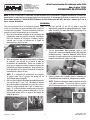
Brass & Nitrophyl Side Hung Float:
Primary Side - 7/64” measured with the fuel bowl
inverted, at the toe of the float to the fuel bowl casting.
Secondary Side - 13/64” measured with the fuel bowl
inverted, at the heel of the float to the fuel bowl casting.
Duracon (Plastic) Side Hung Float:
Primary Side - 7/32” measured with the fuel bowl
inverted, at the toe of the float to the fuel bowl casting.
Secondary Side - 5/16” measured with the fuel bowl
inverted, at the toe of the float to the fuel bowl casting.
Toe
Heel
17. Align the primary metering block gasket onto the
carburetor and place the primary metering block onto
the primary metering block gasket. Place the primary
fuel bowl gasket on the primary metering block and place
the primary fuel bowl onto the primary fuel bowl gasket.
Install the new washers onto the fuel bowl bolts or screws
and fasten the primary fuel bowl to the carburetor.
18. Install the new O-rings onto the fuel transfer tube. Using
a little O-ring lube, install the fuel transfer tube onto the
primary fuel bowl.
19. Align the secondary metering block gasket onto the
carburetor and position the metering backup plate
onto the secondary metering block gasket. Position
the metering plate gasket onto the metering backup
plate and install the metering plate with the clutch head
screws.
20. Apply O-ring lube to the fuel transfer tube and carefully
install the secondary fuel bowl, aligning it with the fuel
transfer tube. Install the washers onto the secondary fuel
bowl bolts or screws and secure the secondary fuel bowl
to the carburetor.
21. Disassemble the vacuum secondary diaphragm assembly
using a Phillips screwdriver. Be careful not to lose the
check ball inside the assembly. Replace the secondary
diaphragm and gasket.
Check Ball
Gasket
22. The rebuild of your 4160-style carburetor is complete.
Adjustments to the idle mix screws may be required.
Please refer to your 4160’s Owner’s Manual for details.
NOTE: Depending on your specific 4160-style carburetor,
there may be some leftover parts after the rebuild.
Page is loading ...
Page is loading ...
Page is loading ...
Page is loading ...
Page is loading ...
Page is loading ...
-
 1
1
-
 2
2
-
 3
3
-
 4
4
-
 5
5
-
 6
6
-
 7
7
-
 8
8
-
 9
9


Edelbrock Carburetor Repair Kit #12750 Fits Most Holley 4160 Carburetors Installation guide
- Type
- Installation guide
- This manual is also suitable for
Ask a question and I''ll find the answer in the document
Finding information in a document is now easier with AI
in other languages
Related papers
-
Edelbrock Carburetor Repair Kit #12760 Fits Most Holley 4150 Carburetors Installation guide
-
-
-
-
-
-
-
Edelbrock 1235 User manual
-
-
Other documents
-
Quick Fuel 34-66QFT Operating instructions
-
Angelo Decor AD93681 Operating instructions
-
Malaguti MADISON 250 User manual
-
 YAMAHA Marine WaveRunner XL700 User manual
-
-
Yamaha WR450F-2007 Owner's manual
-
-
-
-
TOHATSU EVERRUN MWX 50D2 User manual
